
1
Note: This kit must be installed or serviced by a qualifi ed installer, service agency or gas supplier.
These instructions are to be used in conjunction with the main installation instructions for the above
listed models.
WARNING: If these instructions are not followed exactly, a fi re or explosion may result
causing property damage, personal injury or loss of life.
GROUNDING: This power supply must be installed and grounded in accordance with local codes,
or in the absence of local codes, with the current Canadian Electrical Code CSA C22.1. or in the
USA the National Electrical Code ANSI/NFPA70 latest edition.
Description of System
The models 1500, 1700 and 1800 fi replaces have been
designed to accommodate the installation of a 150CFM
air circulation fan. The fan is designed to boost the
natural convection through the heater; this may be a
desirable feature dependent on the fi replace location
and room layout.
It is preferable to install the circulating fan before
completing the heater installation although it may
also be retrofi tted at a later date provided a power out-
let has been prewired within the fi replace casing. Ret-
rofi tting the fan after the fi replace installation is com-
pleted will require disconnecting the gas and removing
the burner module and gas train from the fi replace.
The fan cycles on and off with the burner via a thermal
switch mounted at the fi replace. Power to the fan is
controlled via a wall mounted on/off switch or speed
control (supplied by electrician). These instructions
cover the installation of the fan unit only. For instruc-
tions regarding how and where to locate the power
outlet within the fi replace casing refer to instructions
packaged with the fi replace.
Future servicing or replacement of the fan may be done
through the window aperture of the fi replace without
needing to remove the fi replace from the wall cavity.
1595CFK CIRCULATING FAN KIT
INSTALLATION and OPERATING INSTRUCTIONS
CSA approved for use only with
Valor models 1500, 1700 & 1800 Linear Fireplaces
4002982-03
© 2016, Miles Industries Ltd. All rights reserved.
Operation
To operate the fan, ensure the wall mounted control
is in the “on” position. Light the heater, there will be a
delay for the fan to start until the thermal switch warms
up. After turning the heater “off” the fan will continue to
run for a period until the thermal switch cools.
Note: When the heater is operated at lower settings,
the fan may cycle off and on repeatedly as the thermal
switch temperature cannot be maintained due to the
operation of the fan.
Electrical Requirements
This fan kit requires a power receptacle mounted within
the fi replace casing. The receptacle power will need to
be controlled by a wall switch or speed control as there
is no controller supplied with this kit.
If using a duplex receptacle to provide power for the
ambient lighting option as well, it will be necessary to
“split” the receptacle and run an additional conducter to
maintain separate control of the fan and lighting (see
instructions packaged with the heater).
The fan electrical requirements are 120 Volts, 1 phase,
60 Hz. Full load current of less than 1 amp.
LINEAR SERIES

2
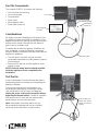
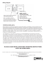
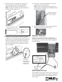
Wiring diagram
and label
Fan Unit
Fan Mounting Plate
ThermalSwitch
Power cable
Considerations
We highly recommend installing this fan (blower) kit to
the appliance before completing the installation of the
appliance otherwise the gas line must be disconnected
and the burner module removed from the fi rebox to
gain access to the blower area.
If installing this fan after the fi replace installation has
been completed, remove the following components
using the fi replace installation manual provided with the
fi replace for guidelines:
• Trim side doors, trim plinth, window, fuel bed,
vermiculate base platform, middle platform supports
(front and back).
• Disconnect the gas line from the appliance at the
appliance valve.
NOTE: Electrical wiring must be already installed
inside the appliance case to complete the fan
installation.
Test the fan
It may be desireable to test the fan operation before
reassembling the burner module and completeing the
fi replace installation.
To test the fan operation the thermal switch can
be temporarily bypassed by connecting the power
cord lead directly to the fan motor (see diagram).
Unplug the power cord from the receptacle before
bypassing the thermal switch. Confi rm fan operation
and speed control (if used) with the thermal switch
bypassed then reconnect thermal switch.
Note: If desireable, the thermal switch may be
left permanently bypassed and the fan controlled
exclusively by the wall switch or speed control.
Fan Kits Components
The complete 1595CFK kit contains the following:
• Fan unit (motor and housing)
• Fan mounting plate
• Thermal switch
• Power cable
• Wiring diagram label
• Sheet metal screws (2)
Sheet metal
screws (2)
Remove wire from
switch and connect
directly to motor for
testing

3
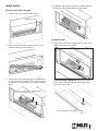
Remove screw
Lift burner module out of fi rebox
Rotate fan into position
Remove burner from fi rebox
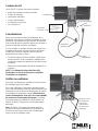
Install the fan
To gain access to the fan area
1. Remove the screw at right end of burner.
2. Slide burner to the right to disengage it from the
orifi ce and lift it out of the fi rebox.
3. Remove the screw maintaining the air defl ector to
the appliance bottom panel. Then, remove the 10
screws around the perimeter of the burner module
plate.
4. Rotate the rear edge of the burner module upwards
and remove the module plate from the fi rebox.
To install the fan
1. Insert the fan through the opening in the fl oor of the
fi rebox and rotate into position.
1700J and 1800J appliances: Remove the plate
to the right of the opening to access fi xing points
for the fan (4 screws).
Remove 1 screw holding air defl ector and
10 screws holding burner plate
Remove fan fi xing access plate (4 screws)

4
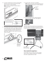
4. Plug the power cord into the receptacle.
Note: Ensure you use the correct receptacle if they
are controlled separately (they should be labelled).
5. Use the self-adhesive wire clamp provided to
secure the cable to the base of the fi replace.
Apply label
Clean the area of sheet metal liner box base adjacent
to the fan, peel the self-adhesive backing from the label
provided with the kit and apply the label to the base.
Reassemble the appliance
Reassemble the unit in reverse order and continue
with the heater installation following the installation
instructions supplied with the heater.
Apply label to
base next to fan
Receptacle
in lower
right corner
of liner box
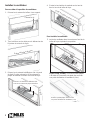
2. Line up the slotted holes in the fan mounting plate
with the holes in the base of the liner box and
fasten using two screws provided.
Note: Push fan as far back as possible before
tightening screws.
3. The thermal switch bracket is fi xed to the underside
of the fi rebox fl oor from the top. Slightly loosen the
two screws holding it and slide the thermal switch
in between the bracket and the underside of the
fi rebox fl oor. Tighten the two screws to secure the
switch in position.
Loosen 2 screws
Slide thermal
switch between
bracket and
underside of
fi rebox fl oor
Secure fan using 2 screws
1700J and 1800J appliances:
secure fan through access hole
Bottom of fi replace transparent for clarity

5
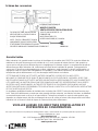
BLOWER BLOWER
THERMAL SWITCH
4003069-01
GROUND WIRE, BLOWER HOUSING TO
STUD ON MOUNTING PLATE
NOTE - ALL WIRING IS SPECIFIC
TO THIS KIT AND SHOULD ONLY BE
REPLACED WITH ORIGINAL EQUIPMENT
WIRING FROM THE MANUFACTURER
MODEL 1595CFK
CIRCULATING FAN KIT
120 V.A.C., 60 Hz, LESS THAN 1 AMP
MANUFACTURED BY
MILES INDUSTRIES LTD.
NORTH VANCOUVER, BC, CANADA
Wiring diagram
PLEASE LEAVE INSTALLATION AND OPERATING INSTRUCTIONS
WITH THE HOMEOWNER.
Limited warranty policy
Miles Industries Ltd. warrants all components of the model 1595CFK Circulating Fan Kit for a period of one year
from the date of purchase against defects in materials or workmanship. This warranty covers only the cost of
defective parts and applies only to the original consumer purchaser. The replacement of defective parts by Miles
Industries Ltd. will be without charge during the warranty period. This warranty does not extend to (1) components
damaged by accident, neglect, misuse, abuse, alteration, and negligence of others, including the installation
thereof by unqualifi ed installers (2) the costs of removal, reinstallation or transportation of defective parts or (3)
incidental or consequential damages.
THIS WARRANTY IS EXPRESSLY IN LIEU OF ALL OTHER WARRANTIES, EXPRESSED OR IMPLIED,
INCLUDING THE WARRANTY OF MERCHANTABILITY OF FITNESS FOR PURPOSE AND OF ALL OTHER
OBLIGATIONS OR LIABILITIES. MILES INDUSTRIES LTD. DOES NOT ASSUME, NOR HAS IT AUTHORIZED
ANY PERSON INCLUDING ITS SALES REPRESENTATIVES TO ASSUME FOR IT, ANY OTHER OBLIGATION
OR LIABILITY IN CONNECTION WITH THE SALE OR USE OF THE MODEL 555CFK CIRCULATING FAN KIT.
A qualifi ed installer, in accordance with the instructions supplied must install the model 1595CFK Circulating Fan Kit.
The defective components should be returned at your expense to the dealer from where the product was purchased
or authorized service agent. The sales invoice evidencing proof of purchase and date of purchase must accompany
any components returned for warranty repair/replacement. Miles Industries Ltd. reserves the right to repair and return
any defective component.
Designed and Manufactured by / for
Miles Industries Ltd.
190 – 2255 Dollarton Highway, North Vancouver, B.C., CANADA V7H 3B1
Tel. 604-984-3496 Fax 604-984-0246
www.valorfi replaces.com
Because our policy is one of constant development and improvement, details may vary slightly from those given in this publication.
Page is loading ...
Page is loading ...
Page is loading ...
Page is loading ...
Page is loading ...
-
 1
1
-
 2
2
-
 3
3
-
 4
4
-
 5
5
-
 6
6
-
 7
7
-
 8
8
-
 9
9
-
 10
10


Ask a question and I''ll find the answer in the document
Finding information in a document is now easier with AI
in other languages
- français: Valor 1595CFK Le manuel du propriétaire
Related papers
-
Valor 1195CFK Owner's manual
-
-
-
-
-
-
-
-
-
Other documents
-
Etac Top-mounted screw set Assembly Instruction
-
Kozyheat Callaway See-Thru Owner's manual
-
NAPOLEON NPI45 User manual
-
-
Fireplace Xtrordinair 4415 ST Gas Fireplace 2015 Owner's manual
-
-
-
Breckwell BH2818i User manual
-
-