Miller SGS 30A CE POWCON Owner's manual
- Category
- Welding System
- Type
- Owner's manual
This manual is also suitable for

November
1996
201
426-001
i~i
Pow
Con
Effective
With
Serial
No.
KG193179
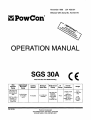
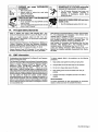
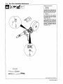
OPERATION
MANUAL
SGS
30A
Wire
Feed
Gun
For
GMAW
WeldIng
CE
Wire
Diameter
Range
Approximate
Wire
Feed
Range
Cooling
Method
Maximum
Spool
Size
Weld
Circuit
Rating
iP
Rating
Overall
Dimensions
Weight
.025
Thru
1/16
in
(0.6
Thru
1.6
mm)
Aluminum
Wire
.025
Thru
045
in
(0.6
Thru
1.1
mm)
Hard
Or
Cored
Wire
70
To
875
ipm
(1.7
To
22.2
mpm)
Air
Cooled
4in
(102
mm)
Diameter
100
Volts,
200
Amperes,
100%
Duty
Cycle
Using
Argon
Shielding
Gas
1P23
Length:
15.3/8
in
(390
mm)
Width:
2-1/2in
(64
mm)
Height:
10-3/4
in
(273
mm)
2.9
lb
(1.3kg)
Gun
Only
141b
(6.4
kg)
Gun
With
Cable
PowCon
Incorporated
8123
Miralani
Drive,
San
Diego,
CA
92126
(619)
621-6300
FAX
(619)
621-6301
OM-183
304
,.
Page is loading ...
Page is loading ...
Page is loading ...

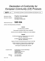
Declaration
of
Conformity
for
European
Community
(CE)
Products
N
OTE
~
This
information
is
provided
for
units
with
CE
certification
(see
rating
label
on
unit).
Manufacturers
Name:
PowCon
Incorporated
Manufacturer~s
Address:
8123
Miralani
Drive
San
Diego,
CA
92126
USA
Declares
that
the
product:
S
G
S
3
O~0~
con
forms
to
the
following
Directives
and
Standards:
Directives
Low
Voltage
Directive:
73/23/EEC
Electromagnetic
Compatibility
(EMC)
Directive:
89/336/EEC
Machinery
Directives:
89/392/EEC,
91/368/EEC,
93/C
133/04,
93/68/EEC
Standards
Arc
Welding
Equipment
Part
I:
Welding
Power
Sources:
IEC
974-1
(April
1995
Draft
Revision)
Arc
Welding
Equipment:
Wirefeed
Systems:
IEC
974-4
(May
1995
Draft
Revision)
Degrees
of
Protection
Provided
By
Enclosures
(lP
Code):
IEC
529:1989
Insulation
Coordination
For
Equipment
With
Low-Voltage
Systems:
Part
I:
Principles,
Requirements
and
Tests:
IEC
664-1:
1992
Electromagnetic
Compatibility,
(EMC):
EN
50199
European
Contact:
Mr.
Stewart
Brown,
European
Sales
Manager
PowCon
(Europe)
Springfield
House,
Water
Lane
Wilmslow,
Cheshire
8K9
5AL
United
Kingdom
Telephone:
44
(0)1625525556
Fax:
44(0)1625537553
dec_coni
1/96
Page is loading ...
Page is loading ...
Page is loading ...

SECTION
1
-
SAFETY
PRECAUTIONS
FOR
ARC
WELDING
OM-163
30411/96
safety_soml
4/95
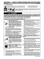
1-1.
Symbol
Usage
4A
Means
Wamingl
Watch
Out!
There
are
possible
hazards
with
this
A
Marks
a
special
safety
message.
procedure!
The
possible
hazards
are
shown
in
the
adjoining
symbols.
~
Means
NOTE;
not
safety
related.
~
This
group
of
symbols
means
Warning!
Watch
Out!
possible
ELECTRIC
SHOCK,
MOVING
PARTS,
and
HOT
PARTS
hazards.
Consult
symbols
and
related
instructions
below
for
necessary
actions
to
avoid
the
hazards.
I
I
~
I
I
1-2.
Arc
Welding
Hazards
a
WARNING
The
symbols
shown
below
are
used
throughout
this
manual
to
call
attention
to
and
identify
possible
hazards.
When
you
see
the
symbol,
watch
out,
and
follow
the
related
instructions
to
avoid
the
hazard.
The
safety
information
given
below
is
only
a
summary
of
the
more
complete
safety
information
found
in
the
Safety
Standards
listed
in
Section
1-4.
Read
and
follow
all
Safety
Standards.
Only
qualified
persons
should
install,
operate,
maintain,
and
repair
this
unit.
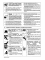
ELECTRIC
SHOCK
can
kill.
Touching
live
electrical
parts
can
cause
fatal
~
shocks
or
severe
burns.
The
electrode
and
work
~
circuit
is
electrically
live
whenever
the
output
is
on.
The
input
power
circuit
and
machine
internal
circuits
are
also
live
when
power
is
on.
In
semiautomatic
or
automatic
wire
welding,
the
wire,
wire
reel,
drive
roll
housing,
and
all
metal
parts
touching
the
welding
wire
are
electrically
live.
Incorrectly
installed
or
improperly
grounded
equipment
is
a
hazard.
1.
Do
not
touch
live
electrical
parts.
2.
Wear
dry,
hole-free
insulating
gloves
and
body
protection.
3.
Insulate
yourself
from
work
and
ground
using
dry
insulating
mats
or
covers
big
enough
to
prevent
any
physical
contact
with
the
work
or
ground.
4.
Disconnect
input
power
or
stop
engine
before
installing
or
servicing
this
equipment.
Lockout/tagout
input
power
according
to
OSHA
29
CFR
191
0.147
(see
Safety
Standards).
5.
Properly
install
and
ground
this
equipment
according
to
its
Owners
Manual
and
national,
state,
and
local
codes.
6.
Always
verify
the
supply
ground
check
and
be
sure
that
input
now~r
r~ord
nroiinrl
wir~
i~
nronArhf
t~onn~rthrI
to
nroiinrl
terminal
in
disconnect
box
or
that
cord
plug
is
connected
to
a
properly
grounded
receptacle
outlet.
7.
When
making
input
connections,
attach
proper
grounding
conductor
first
double-check
connections.
8.
Frequently
inspect
input
power
cord
for
damage
or
bare
wiring
replace
cord
immediately
if
damaged
bare
wiring
can
kill.
9.
Turn
off
all
equipment
when
not
in
use.
10.
Do
not
use
worn,
damaged,
undersized,
or
poorly
spliced
cables.
11.
Do
not
drape
cables
over
your
body.
12.
If
earth
grounding
of
the
workpiece
is
required,
ground
it
directly
with
a
separate
cable
do
not
use
work
clamp
or
work
cable.
13.
Do
not
touch
electrode
if
you
are
in
contact
with
the
work,
ground,
or
another
electrode
from
a
different
machine.
14.
Use
only
well-maintained
equipment.
Repair
or
replace
damaged
parts
at
once.
Maintain
unit
according
to
manual.
15.
Wear
a
safety
harness
if
working
above
floor
level.
16.
Keep
all
panels
and
covers
securely
In
place.
17.
Clamp
work
cable
with
good
metal-to-metal
contact
to
workoiAr~A
or
wnrkthhlA
~q
nA~r
thct
wnlrf
~q
nr~ittk~iI
NOISE
ARC
RAYS
can
burn
eyes
and
skin;
NOISE
can
damage
hearing;
FLYING
SLAG
OR
SPARKS
can
injure
eyes.
Arc
rays
from
the
welding
process
produce
intense
visible
and
invisible
(ultraviolet
and
infrared)
rays
that
can
bum
eyes
and
skin.
Noise
from
some
processes
can
damage
hearing.
Chipping,
grinding,
and
welds
cooling
throw
off
pieces
of
metal
or
slag.
1.
Use
approved
ear
plugs
or
ear
muffs
if
noise
level
Is
high
FUMES
AND
GASES
can
be
hazardous
to
your
health.
Welding
produces
fumes
and
gases.
Breathing
these
fumes
and
gases
can
be
hazardous
to
your
health.
Keep
your
head
out
of
the
fumes.
Do
not
breathe
the
fumes.
If
inside,
ventilate
the
area
and/or
use
exhaust
at
the
arc
to
remove
welding
fumes
and
gases.
3.
If
ventilation
is
poor,
use
an
approved
air-supplied
respirator.
4.
Read
the
Material
Safety
Data
Sheets
(MSDS5)
and
the
manufacturers
instruction
for
metals,
consumables,
coatings,
cleaners,
and
degreasers.
ARC
RAYS
2.
Wear
a
welding
helmet
fitted
with
a
proper
shade
of
filter
to
protect
your
face
and
eyes
when
welding
or
watching
(see
ANSI
Z49.1
and
Z87.1
listed
in
Safety
Standards).
3.
Wear
approved
safety
glasses
with
side
shields.
4.
Use
protective
screens
or
barriers
to
protect
others
from
flash
and
glare;
warn
others
not
to
watch
the
arc.
5.
Wear
protective
clothing
made
from
durable,
flame-resistant
material
(wool
and
leather)
and
foot
protection.
5.
Work
in
a
confined
space
only
if
it
is
well
ventilated,
or
while
wearing
an
air-supplied
respirator.
Always
have
a
trained
watchperson
nearby.
Welding
fumes
and
gases
can
displace
air
and
lower
the
oxygen
level
causing
injury
or
death.
Be
sure
the
breathing
air
is
safe.
6.
Do
not
weld
in
locations
near
degreasing,
cleaning,
or
spraying
operations.
The
heat
and
rays
of
the
arc
can
react
with
vapors
to
form
highly
toxic
and
irritating
gases.
7.
Do
not
weld
on
coated
metals,
such
as
galvanized,
lead,
or
cadmium
plated
steel,
unless
the
coating
is
removed
from
the
weld
area,
the
area
is
well
ventilated,
and
if
necessary,
while
wearing
an
air-supplied
respirator.
The
coatings
and
any
metals
containing
these
elements
can
give
off
toxic
fumes
if
welded.
During
operation,
keep
everybody,
especially
children,
away.
1.
2.
OM-183
304
Page
1
Page is loading ...

CYLINDERS
can
explode
if
damaged.
Shielding
gas
cylinders
contain
gas
under
high
pressure.
If
damaged,
a
cylinder
can
explode.
Since
gas
cylinders
are
normally
part
of
the
welding
process,
be
sure
to treat
them
carefully.
1.
Protect
compressed
gas
cylinders
from
excessive
heat,
mechanical
shocks,
slag,
open
flames,
sparks,
and
arcs.
2.
Install
cylinders
in
an
upright
position
by
securing
to
a
stationary
support
or
cylinder
rack
to
prevent
falling
or
tipping.
3.
Keep
cylinders
away
from
any
welding
or
other
electrical
circuits.
4.
Never
drape
a
welding
torch
over
a
gas
cylinder.
5.
Never
allow
a
welding
electrode
to
touch
any
cylinder.
6.
Never
weld
on
a
pressurized
cylinder
explosIon
will
result.
7.
Use
only
correct
shielding
gas
cylinders,
regulators,
hoses,
and
fittings
designed
for
the
specific
application;
maintain
them
and
associated
parts
in
good
condition.
8.
Turn
face
away
from
valve
outlet
when
opening
cylinder
valve.
9.
Keep
protective
cap
in
place
over
valve
except
when
cylinder
is
in
use
or
connected
for
use.
10.
Read
and
follow
instructions
on
compressed
gas
cylinders,
associated
equipment,
and
CGA
publication
P-i
listed
in
Safety
Standards.
WELDING
can
cause
fire
or
explosion.
Welding
on
closed
containers,
such
as
tanks,
drums,
or
pipes,
can
cause
them
to
blow
up.
Sparks
can
fly
off
from
the
welding
arc.
The
flying
sparks,
hot
workpiece,
and
hot
equipment
can
cause
fires
and
burns.
Accidental
contact
of
electrode
to
metal
objects
can
cause
sparks,
explosion,
overheating,
or
fire.
Check
and
be
sure
the
area
is
safe
before
doing
any
welding.
1.
Protect
yourself
and
others
from
flying
sparks
and
hot
metal.
2.
Do
not
weld
where
flying
sparks
can
strike
flammable
material.
3.
Remove
all
flammables
within
35
ft
(10.7
m)
of
the
welding
arc.
If
this
is
not
possible,
tightly
cover
them
with
approved
covers.
4.
Be
alert
that
welding
sparks
and
hot
materials
from
welding
can
easily
go
through
small
cracks
and
openings
to
adjacent
areas.
5.
Watch
for
fire,
and
keep
a
fire
extinguisher
nearby.
6.
Be
aware
that
welding
on
a
ceiling,
floor,
bulkhead,
or
partition
can
cause
fire
on
the
hidden
side.
7.
Do
not
weld
on
closed
containers
such
as
tanks,
drums,
or
pipes,
unless
they
are
properly
prepared
according
to
AWS
F4.
1
(see
Safety
Standards).
8.
Connect
work
cable
to
the
work
as
close
to
the
welding
area
as
practical
to
prevent
welding
current
from
traveling
long,
possibly
unknown
paths
and
causing
electric
shock
and
fire
hazards.
9.
Do
not
use
welder
to
thaw
frozen
pipes.
10.
Remove
stick
electrode
from
holder
or
cut
off
welding
wire
at
contact
tip
when
not
in
use.
11.
Wear
oil-free
protective
garments
such
as
leather
gloves,
heavy
shirt,
cuffless
trousers,
high
shoes,
and
a
cap.
12.
Remove
any
combustibles,
such
as
a
butane
lighter
or
matches,
from
your
person
before
doing
any
welding.
1-3.
Additional
Installation,
Operation,
And
Maintenance
Hazards
FIRE
OR
EXPLOSION
can
result
from
placing
unit
on,
over,
or
near
combustible
surfaces.
1.
Do
not
locate
unit
on,
over,
or
near
combustible
surfaces.
2.
Do
not
install
unit
near
flammables.
FALLING
EQUIPMENT
can
cause
serious
personal
injury
and
equipment
damage.
1.
Use
lifting
eye
to
lift
unit
only,
NOT
running
gear,
gas
cylinders,
or
any
other
accessories.
Use
equipment
of
adequate
capacity
to
lift
unit.
If
using
lift
forks
to
move
unit,
be
sure
forks
are
long
enough
to
extend
beyond
opposite
side
of
unit.
HOT
PARTS
can
cause
severe
burns.
1.
Do
not
touch
hot
parts
bare
handed.
2.
Allow
cooling
period
before
working
on
gun
or
torch.
MOVING
PARTS
can
cause
injury.
1.
Keep
away
from
moving
parts
such
as
fans.
2.
Keep
all
doors,
panels,
covers,
and
guards
closed
and
securely
in
place.
MAGNETIC
FIELDS
FROM
HIGH
CURRENTS
can
affect
pacemaker
operation.
i.
Pacemaker
wearers
keep
away.
2.
Wearers
should
consult
their
doctor before
going
near
arc
welding,
gouging,
or
spot
welding
operations.
MOVING
PARTS
can
cause
injury.
1.
Keep
away
from
moving
parts.
2.
Keep
away
from
pinch
points
such
as
drive
rolls.
FLYING
PIECES
OF
METAL
or
DIRT
can
injure
eyes.
1.
Wear
safety
glasses
with
side
shields
or
face
shield.
WELDING
WIRE
can
cause
puncture
wounds.
1.
Do
not
press
gun
trigger
until
instructed
to
do
so.
2.
Do
not
point
gun
toward
any
part
of
the
body,
other
people,
or
any
metal
when
threading
welding
wire.
HIGH-FREQUENCY
RADIATION
can
interfere
with
radio
navigation,
safety
services,
computers,
and
communications
equipment.
1.
Have
only
qualified
persons
familiar
with
electronic
equipment
perform
this
installation.
2.
The
user
is
responsible
foi
having
a
qualified
electrician
promptly
correct
any
interference
problem
resulting
from
the
installation.
3.
If
notified
by
the
FCC
about
interference,
stop
using
the
equipment
at
once.
4.
Have
the
installation
regularly
checked
and
maintained.
5.
Keep
high-frequency
source
doors
and
panels
tightly
shut,
keep
spark
gaps
at
correct
setting,
and
use
grounding
and
shielding
to
minimize
the
possibility
of
interference.
2.
3.
OM-183
304
Page
2
Page is loading ...

OVERUSE
can
cause
OVERHEATED
EQUIPMENT.
1.
Allow
cooling
period.
2.
Reduce
current
or
reduce
duty
cycle
before
starting
to
weld
again.
Follow
rated
duty
cycle.
1-4.
Principal
Safety
Standards
1-5.
EMF
Information
SIGNIFICANT
DC
VOLTAGE
exists
after
removal
of
input
power
on
inverters.
1.
Turn
Oft
inverter,
disconnect
input
power,
and
discharge
input
capacitors
according
to
instructions
in
Maintenance
Section
before
touchinq
any
parts.
BUILDUP
OF
SHIELDING
GAS
can
harm
health
or
kill.
1.
Shut
off
shielding
gas
supply
when
not
in
use.
STATIC
ELECTRICITY
can
damage
parts
on
circuit
boards.
1.
Put
on
grounded
wrist
strap
BEFORE
handling
boards
or
parts.
Use
proper
static-proof
bags
and
boxes
to
store,
move,
or
ship
PC
boards.
Safety
in
Welding
and
Cutting,
ANSI
Standard
Z49.1,
from
American
Welding
Society,
550
N.W.
LeJeune
Rd,
Miami
FL
33126
Safety
and
Health
Standards,
OSHA
29
CFR
1910,
from
Superintendent
of
Documents,
U.S.
Government
Printing
Office,
Washington,
D.C.
20402.
Recommended
Safe
Practices
for
the
Preparation
for
Welding
and
Cutting
of
Containers
That
Have
Held
Hazardous
Substances,
American
Welding
Society
Standard
AWS
F4.1,
from
American
Welding
Society,
550
N.W.
LeJeune
Rd,
Miami,
FL
33126
National
Electrical
Code,
NFPA
Standard
70,
from
National
Fire
Protection
Association,
Batterymarch
Park,
Quincy,
MA
02269.
Safe
Handling
of
Compressed
Gases
in
Cylinders,
CGA
Pamphlet
P-i,
from
Compressed
Gas
Association,
1235
Jefferson
Davis
Highway,
Suite
501,
Arlington,
VA
22202.
Code
for
Safety
in
Welding
and
Cutting,
CSA
Standard
Wi
17.2,
from
Canadian
Standards
Association,
Standards
Sales,
178
Rexdale
Boulevard,
Rexdale,
Ontario,
Canada
M9W
I
R3.
Safe
Practices
For
Occupation
And
Educational
Eye
And
Face
Protection,
ANSI
Standard
Z87.1,
from
American
National
Standards
Institute,
1430
Broadway,
New
York,
NY
10018.
Cutting
And
Welding
Processes,
NFPA
Standard
51B,
from
National
Fire
Protection
Association,
Batterymarch
Park,
Quincy,
MA
02269.
Considerations
About
Welding
And
The
Effects
Of
Low
Frequency
Electric
And
Magnetic
Fields
The
following
is
a
quotation
from
the
General
Conclusions
Section
of
the
U.S.
Congress,
Office
of
Technology
Assessment,
Biological
Effects
of
Power
Frequency
Electric
&
Magnetic
Fields
Backg
round
Paper,
OTA-BP-E-53
(Washington,
DC:
U.S.
Government
Printing
Office,
May
1989):
.
. .
there
is
now
a
very
large
volume
of
scientific
findings
based
on
experiments
at
the
cellular level
and
from
studies
with
animals
and
people
which
clearly
establish
that
low
frequency
magnetic
fields
can
interact
with,
and
produce
changes
in,
biological
systems.
While
mostof
this
work
is
of
very
high
quality,
the
results
are
complex.
Current
scientific
understanding
does
not
yet
allow
us
to
interpret
the
evidence
in
a
single
coherent
framework.
Even
more
frustrating,
it
does
not
yet
allow
us
to
draw
definite
conclusions
about
questions
of
possible
risk
or
to
offer
clear
science-based
advice
on
strategies
to
minimize
or
avoid
potential
risks.
To
reduce
magnetic
fields
in
the
workplace,
use
the
following
procedures:
1.
Keep
cables
close
together
by
twisting
or
taping
them.
2.
Arrange
cables
to
one
side
and
away
from
the
operator.
3.
Do
not
coil
or
drape
cables
around
the
body.
4.
Keep
welding
power
source
and
cables
as
far
away
as
practical.
5.
Connect
work
clamp
to
workpiece
as
close
to
the
weld
as
possible.
About
Pacemakers:
The
above
procedures
are
also
recommended
for
pacemaker
wearers.
Consult
your
doctor
for
complete
information.
OM-183
304
Page
3
Page is loading ...
Page is loading ...
Page is loading ...
Page is loading ...
Page is loading ...
Page is loading ...
Page is loading ...

SECTION
2-
DEFINITIONS
2-1.
Manufacturers
Rating
Label
For
CE
Products
2-2.
Symbols
And
Definitions
NOTE
~
Some
symbols
are
found
only
on
CE
products.
U1
Primary
Voltage
\(
Volts
Primary
Current
Amperes
I
P
Degree
Of
Protection
(J
2
Conventional
Load
Voltage
12
Rated
Welding
Current
X
Du~, Cycle
O,/,
Percent
E
1
U1=30V
11=1A
~
1P23
U2100V
12=200A
X100%
Powcon
Incorporated,
San
Diego,
CA
USA
S-182
589
For
label
location
see
Section
4-1.
S-182
589
OM-183
304
Page
7
Page is loading ...

SECTION
3-INSTALLATION
N
OT
E
iri~
Use
weld
control
or
welding
power
source
Owner~s
Manual
during
gun
installation.
If
contact
tip,
line,;
and
drive
roll
groove
are
not
correct
for
wire size
and
type,
see
Section
5
to
change
parts
as
needed.
See
Parts
List
for
other
available
contact
tips.
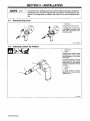
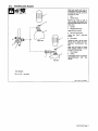
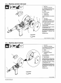
3-1.
Removing
Top
Cover
1
Top
Cover
Push
back
and
lift
off
as
shown.
To
reinstall
cover,
set
rear
of
cover
in
gun/feeder,
and
push
cover
back,
down,
and
forward
until
it
clicks
into
position.
Rot.
ST.150
882-A
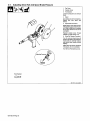
3-2.
Adjusting
Contact
Tip
Position
3,
4
1
Contact
Tip
2
Nozzle
Adjusting
barrel
changes
contact
tip
location
from
1/16
in
(1.6
mm)
out
end
of
nozzle
to
1/4
in
(6.3
mm)
inside
nozzle.
For
aluminum
welding,
contact
tip
should
be
at
least
1/8
in
(3.2
mm)
inside
nozzle.
For
steel
welding,
contact
tip
should
be
flush
with
end
of
nozzle.
3
Jam
Nut
4
Barrel
To
change
contact
tip
location,
loosen
jam
nut,
and
turn
barrel.
Tighten
jam
nut.
ST.150
434
OM-183
304
Page
8
Page is loading ...

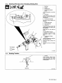
3-3.
Installing
Wire
Spool
And
Threading
Welding
Wire
3-4.
Rotating
Canister
*4
1
Top
Cover
2
Canister
3
Canister
Cover
4
Thumbscrew
(Canister
Cover)
Loosen
thumbscrew
and
remove
cover.
5
Wire
Spool
Loosen
wire
from
spool,
cut
off
bent
wire,
and
pull
Gin
(150mm)
of
wire
off
spool.
6
Pressure
Roll
Assembly
Lift
arm
and
open
pressure
roll
assembly.
7
Canister
Inlet
Guide
8
Drive
Roll
Groove
9
Contact
Tip
Thread
wire
through
canister
inlet
guide,
along
drive
roll
groove,
and
out
contact
tip.
Install
spool
so
wire
feeds
off
bottom.
10
Spool
Brake
Thumbnut
If
necessary,
turn
thumbnut
coun
terclockwise
slightly
to
install
spool.
11
Thumbscrew
(Canister
Rotation)
Loosen
thumbscrew
to
rotate
can
ister
(see
Section
3-4).
Close
and
secure
pressure
roll
assembly.
Reinstall
top
cover
and
canister
cover.
5T~15O
436
10
Tools
Needed:
9
5
4
1
Canister
Loosen
canister
rotation
thumb
screw
(see
Section
3-3).
Move
canister
to
desired
position.
Tight
en
thumbscrew.
Rear
View
ST-150
433-A
OM-1
83304
Page
9
Page is loading ...

3-5.
Connecting
To
24
Volt
Weld
Control
1
Gas
Hose
2
lOft
(3m)
Gas
Hose
With
5/8
in
Adapter
Fitting
Connect
fitting
to
gun/feeder
gas
hose
and
remaining
end
to
regula
tor/flowmeter
(see
Section
3-6).
3
24
Volt
Weld
Control
4
Trigger
Control
Cord
Insert
plug
into
receptacle,
and
tighten
threaded
collar.
5
Weld
Cable
Connect
to
positive
(+)
weld
output
terminal
on
welding
power
source
according
to
its
Owners
Manual.
2
1
3
Tools
Needed:
1-1/8,5/8in
Ref.
ST-150
917-A
OM-183
304
Page
10
Page is loading ...

3-6.
Installing
Gas
Supply
Tools
Needed:
1-1/8,5/Bin
2
Obtain
gas
cylinder
and
chain
to
running
gear,
wall,
or
other
station
ary
support
so
cylinder
cannot
tall
and
break
off
valve.
1
Cap
2
Cylinder
Valve
Remove
cap,
stand
to
side
of
valve,
and
open
valve
slightly.
Gas
flow
blows
dust
and
dirt
from
valve.
Close
valve.
3
Cylinder
4
Regulator/Flowmeter
Install
so
face
is
vertical.
5
Gas
Hose
Connection
Fitting
has
5/8-18
right-hand
threads.
6
Flow
Adjust
Typical
flow
rate
is
20
cfh
(cubic
feet
per
hour).
Check
wire
man
ufacturers
recommended
flow
rate.
Make
sure
flow
adjust
is
closed
when
opening
cylinder
to
avoid
damage
to
the
flowmeter.
7
CO2
Adapter
.3
8
0-Ring
Install
adapter
with
0-ring
between
regulator/flowmeter
and
CO2
cylinder.
ssb3.V
5/94
ST-158
697-A
Argon
Gas
4
CO2
Gas
OM-1
83304
Page
11
Page is loading ...

3-7.
Adjusting
Drive
Roll
And
Spool
Brake
Pressure
1
Top
Cover
2
Canister
Cover
3
Thumbscrew
Loosen
thumbscrew
and
remove
cover.
5
4
Spool
Cut
welding
wire
off
at
contact
tip.
Retract
wire
onto
spool
and
secure.
5
Spool
Brake
Thumbnut
Grasp
spool
in
one
hand
and
turn
while
adjusting
spool
brake
thumb-
nut.
When
a
slight
force
is
needed
to
turn
spool,
tension
is
set.
Do
not
overtighten.
Reinstall
canister
cover.
Thread
welding
wire
(see
Section
3-3).
6
Drive
Roll
Tension
Thumbnut
Turn
On
unit
and
check
drive
roll
pressure
by
feeding
wire
against
a
wood
board
or
concrete
surface;
wire
should
feed
steadily
without
slipping.
Adjust
drive
roll
tension
thumbnut
if
necessary.
Do
not
overtighten.
Turn
Off
unit.
Reinstall
top
cover.
Tools
Needed:
Ret.
ST-151
1121S-0651
OM-1
83304
Page
12
Page is loading ...

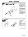
SECTION
4-
OPERATION
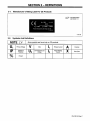
3
Gun
Trigger
Open
valve
on
cylinder
just
before
welding.
Gun
trigger
turns
weld
output
and
gas
flow
on
and
off.
For
shielding
gas
preflow
and
postf
low,
lightly
press
trigger
before
and
after
welding.
4-1.
Controls
~%
~
1
Trigger
Press
trigger
to
energize
welding
power
source
contactor
(if
applica
ble),
start
shielding
gas
flow,
and
begin
wire
feed.
For
shielding
gas
preflow
and
post-
flow,
lightly
press
trigger
before
and
after
welding.
2
Trigger
Hold
Button
Use
button
to
continually
feed
wire
without
holding
down
the
trigger.
Press
button
while
pressing
the
trigger,
release
trigger,
and
wire
continues
to
feed
until
trigger
is
pressed
again.
3
Wire
Speed
Control
4
2
1
Use
control
to
adjust
wire
feed
speed.
The
numbers
in
the
open
ing
are
not
a
wire
feed
speed
and
are
for
reference
only.
4
Rating
Label
Location
4-2.
3
Shielding
Gas
Rot
SB-147
741-A
2
1
1
Shielding
Gas
Cylinder
2
Valve
Close
valve
on
cylinder
when
fin
ished
welding.
sb5.1
6/92
5-0621-C
/
Ref.
SB-147
741-A
OM-183
304
Page
13
Page is loading ...

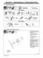
SECTION
5-
MAINTENANCE
&
TROUBLESHOO11NG
5-1.
Routine
Maintenance
Tools
Needed:
Remove
top
cover
and
open
pres
sure
roll
assembly
as
shown
in
Section
5-3.
1
Contact
Tip
Wrench
Insert
wrench
into
nozzle
over
con
tact
tip.
2
Compression
Nut
Loosen
nut.
Pull
out
contact
tip.
3
Contact
lip
4
Nozzle
Pull
wire
out
nozzle
and
liner
should
slide
out.
If
necessary,
tilt
nozzle
down
to
remove
liner.
Close
pressure
roll
assembly.
Re
install
top
cover.
Install
new
liner
and
contact
tip
over
wire.
Cut
off
wire
at
end
of
contact
tip.
lighten
nut
just
until
contact
tip
is
secure.
Overtightening
nut
will
damage
adapter.
5-2.
Changing
Contact
Tip
And
Liner
2
3
ST-150
437
OM-183
304
Page
14
Page is loading ...

5-3.
Gun
Drive
Assembly
Maintenance
Tools
Needed:
5/16
in
Retract
wire
onto
spool.
1
Setscrew
2
Drive
Roll
Use
wire
brush
to
clean
drive
roll.
Install
drive
roll
with
desired
groove
down,
and
turn
drive
roll
so
one
setscrew
faces
flat
side
of
shaft.
3
Bearing
Use
wire
brush
to
clean
bearing.
Line
up
drive
roll
groove
with
bear
ing
groove
and
liner
opening.
Tighten
setscrews.
Thread
welding
wire
through
gun
(see
Section
3-3
in
the
Owners
Manual).
Close
and
secure
pres
sure
roll
assembly.
Adjust
drive
roll
pressure,
it
necessary
(see
Sec
tion
3-8
in
the
Owners
Manual).
Reinstall
top
cover.
Ref.
ST.149
967-B
/
Ref.
ST-800
945-A
OM-183
304
Page
15
Page is loading ...

5-4.
Replacing
Canister
Inlet
Guide
Close
pressure
roll
assembly.
Ad
just
spool
brake
pressure
and
drive
roll
pressure
if
necessary
(see
Section
3-7).
1
Top
Cover
2
Pressure
Roll
Assembly
Cutoff
welding
wire
where
it
enters
pressure
roll
assembly
area.
7
6
3
Nozzle
Pull
wire
out
nozzle.
4
Thumbscrew
5
Canister
Cover
Loosen
thumbscrew
and
remove
cover.
6
Wire
Spool
7
Spool
Brake
Thumbnut
Loosen
thumbnut,
retract
wire
onto
spool,
secure,
and
remove
spool.
8
Canister
Inlet
Guide
Turn
counterclockwise
to
remove.
Install
new
guide.
Reinstall
spool
and
thread
welding
wire
(see
Section
3-3).
Tools
Needed:
Reinstall
covers.
5-5.
Replacing
Spool
Canister
P1
~
Ref.
ST-150
436
/
Rot.
ST.149
967-B
1
Top
Cover
2
Pressure
Roll
Assembly
Cutoff
welding
wire
where
it
enters
pressure
roll
assembly
area.
3
Nozzle
Pull
wire
out
nozzle.
4
Thumbscrew
(Canister
Rotation)
Turn
thumbscrew
counterclock
wise
three
full
turns.
5
Spool
Canister
Remove
as
shown.
Push
new
can
ister
into
wire
drive
housing
until
fully
seated.
Tighten
thumbscrew.
Install
spool
and
thread
welding
wire
(see
Section
3-3).
2
Close
pressure
roll
assembly.
Ad
just
spool
brake
pressure
and
drive
roll
pressure
as
necessary
(see
Section
3-7).
Reinstall
covers.
Tools
Needed:
Ref.
ST-149
967-B
OM-183
304
Page
16
Page is loading ...

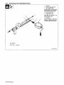
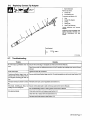
5-6.
Replacing
Contact
Tip
Adapter
1
Barrel
Extension
Remove
as
shown.
2
Contact
Tip
3
Compression
Nut
To
remove,
see
Section
5-2.
4
Liner
5
Contact
Tip
Adapter
6
0-Ring
7
Head
Tube
8
Head
Tube
Setscrew
Loosen
setscrews
and
remove
adapter.
Install
new
0-ring
and
adapter,
and
tighten
setscrews.
Reinstall
con
tact
tip,
compression
nut,
and
nozzle.
Trouble
Remedy
No
weld
output;
gun/feeder
does
not
work.
Secure
weld
control
plug
in
receptacle
(see
weld
control
Owners
Manual).
.
Place
Power
switch
on
welding
power
source
in
the
On
position
(see
welding
power
source
Owners
Manual).
Erratic
weld
output.
Tighten
and
clean
all
connections.
Pressing
gun/feeder
trigger
does
not
energize
weld
control;
welding
wire
is
not
energized;
shielding
gas
does
not
flow.
Secure
plug
from
gun/feeder
trigger
cord
into
10-socket
receptacle
on
weld
control
(see
Section
3-5).
~
Wire
does
not
feed;
burnback
in
contact
tip.
Reinstall
current
pick-up
tab
if
applicable
(see
Section
5-3).
Wire
feeds,
shielding
gas
flows,
but
welding
wire
is
not
energized.
Secure
control
cable leads
in
weld
control
(see
weld
control
Owners
Manual).
. .
See
Troubleshooting
section
in
welding
power
source
Owners
Manual.
Wire
feeds
erratically.
Check
and
correct
drive
roll
pressure
(see
Section
3-7).
Clean
drive
roll
or
replace
drive
roll
(see
Section
5-3).
Decrease
spool
brake
pressure
(see
Section
3-7).
7
5
2
1
5-7.
Troubleshooting
Tools
Needed:
F
~
3/32
in
5T-150
430-B
OM-1
83304
Page
17
Page is loading ...
Page is loading ...
Page is loading ...
Page is loading ...
Page is loading ...

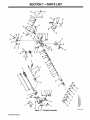
SECTION
7-PARTS
LIST
cJ
N-
N
U,
N
co~Z
(I,
EE
V
Figure
7-1.
Complete
Assembly
ST-143
116-H
U)
U)
cJ
U,
Lt)
0
Lfl~
0)
-0)
(0
0
cJ
N
0)
~
It)
(0
0)
N
OM-183
304
Page
20
Page is loading ...

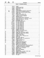
Figure
7-1.
Complete
Assembly
133479
..
COVER
1
135196
..
SPRING,closurecover
1
133
362
..
STRAIN
RELIEF,
cable
1
182824
..
HOSE,
gas
in
1
138
459
..
CABLE,
control
1
137
854
..
POTENTIOMETER,
C
sltd
sft
l/T
.5W 10K
ohm
1
000 369
..
SWITCH,
lim
1OA
125/25OVAC
DPST
plgr
1
073 476
..
CLAMF~
strap
rbr
5
holes
.375
wide
x
4.625
Ig
13
137
479
..
CABLE,
power
1
152
577
..
STRIP,
cop
.010
x
2.000
x
.750
1
137
495
..
FITTING,
connection
power
weld
1
141
694
..
SCREW,
set
.312-18
x
.375sch
stl
1
144
861
..
WASHER,
anti-turn
1
135
127
..
LOCK,
shaft
pot
.250-32
x
.l2Sdia
shaft
1
134
856
..
KNOB,
speed
control
1-10.140
shaft
x
1.125
OD
1
602
169
..
SCREW,
set
stl
sch
8-32
x
.187
cup
pt
1
144
862
..
EXTENSION,
nozzle
1
156
821
..
EXTENSION,
barrel
2.875
Ig
1
TIP~
contact
.025/31
wire
1
TIP,
contact
.030/36
wire
1
TlP~
contact
.030/41
wire
1
TIP,
contact
.035/41
wire
1
TIP,
contact
.035/52
wire
1
TlP~
contact
.047/52
wire
1
TIP,
contact
.047/61
wire
1
TIP,
contact
.062/73
wire
1
TIP,
contact
.062/81
wire
1
136821
..
WRENCH,
nut
tip
contact
1
166
575
..
WRENCH,
hex
.078
across
the
flat
1
136
748
..
NUT
.375-24
.4ldia
sti
1
136
683
..
LINER,
teflon
.045-1/16
wire
x
6.875
Ig
1
136
682
..
LINER,
teflon
.023-.035
wire
x
6.875
Ig
1
164
421
..
ADAPTER,
contact
tip
1
164
485
..
0-RING
.176
ID
x
.O7OCS
2
604
612
..
SCREW,
set
8-32
x
.125
cup
pt
sch
stl
1
164422
..
TUBE,
head
1
058 685
..
NUT,
1.000-8
1
.5knrl
nyl
1
602
172
..
SCREW,
set
10-32
x
.187
cup
point
sch
stl
1
164
423
..
ADAPTER,
tip
head
1
134800
..
0-RING,
.614
lDx.O7OCS
2
133
365
..
CLAMP~
head
tube
1
000
417
..
SCREW,
10-24
xl
.000sochd
hex
2
162
041
..
BEARING
BLOCK
ASSEMBLY
1
604
638
..
SCREW,
6-32
x
.375sochd
hex
3
143
480
..
SCREW,
6-32
x
.625sochd
hex
sti
1
136 135
..
ROLL,
drive
VK
groove
.023-1/16
wire
(consisting
of)
1
604
612
....
SCREW,
set
sti
sch
8-32
x
.125
cup
point
2
114
045
..
SCREW,
6-32
x
.S00hexwhd
sit stl
slffmg
2
602
198
..
WASHER,
lock
.141
ID
sti
split
1
182
279
..
SHAFT,
hot
idler
1
182
948
..
DRIVE
ROLL
ASSEMBLY
1
132
852
..
ARM,
pressure
1
605 798
..
WASHER,
shldr
nyl
.375
OD
x
.168
ID
x
.080
2
133083
..
SPRING,tensionadjdriveroll
1
144
860
..
SCREW,
8-32
x
.437flathd
sit
stl
1
058968
..
RING,
retainerE
2
135
474
..
PIN,
hinge
1
OM-183
304
Page
21
Item
Dia.
Part
No.
Mkgs.
No.
Description
Quantity
R4
PB1....
11
13
14
19
.136
171
19
.135427
19
.135428
19
.147314
19
135430
19
.135429
19
135424
19
.135426
19
.135425
Page is loading ...

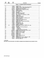
Figure
7-1.
Complete
Assembly
(Continued)
155
565
..
SCREW,
thumb
1
134799
..
0-RING,
.176
IDx.O7OCS(usedw/thumbscrew)
1
135 126
..
SCREW,
set
6-32
x
.125
cup
point
sch
stl
1
602
209
..
WASHER,
tooth
.256
ID
stl
intl
1
602
154
..
SCREW,
.250-20
x
.500hexhd
stl
slffmg
1
132
527
..
CANISTER,
spool
1
148
488
..
POST,
support
spool
1
132529
..
PAD,
brake
1
148
489
..
WASHER,
anti-turn
.380
ID
1
132
524
..
NUT,
.375-24
.S6knrI
alum
1
000
364
..
RING,
retainer
ext
.145
shaft
grv
x
.O25thk
1
132
526
..
COVER,
spool
1
132
528
..
SCREW,
thumb
canister
1
132
521
..
GUIDE,
inlet
canister
1
112
896
..
SPRING,
cprsn
.240
OD
x
.020
wire
x
.437
2
135
773
..
NUT,
8-32
.56knrI
stl
1
143
360
..
SCREW,
8-32
x
.500panhd
phi
sti
1
136679
..
CLAMP,
strain
relief
1
129
351
..
SCREW,
8-32
x
.500hexwhd
sIt
stl
slffmg
1
164
591
..
CASE,
gun
LH
1
173
527
..
SCREW,
8-32
x
1.500
2
135896
..
PLUNGER,triggerhold
1
173
528
..
SCREW,
8-32
x
.875
1
161
813
..
MOTOR,
gear
PM
24VDC
420RPM
10.2:1
ratio
1
164592
..
TRIGGER
1
164
582
..
HOUSING,
wire
drive
(consisting
of)
1
058 262
....
CAF~
valve
1
135
580
....
FITTING,
gas
1
146
555
....
SCREW,
set
8-32
x
.125
cup
sch
2
.009
925
..
NOZZLE,
spot
outside
corner
.937
ID
x
2.375
1
050
116
..
NOZZLE,13/l6ortxl-5/81g
1
050
115
..
NOZZLE,
1/2
ort
x
1-5/8
Ig
1
050
622
..
NOZZLE,
5/8
art
x
1-5/8
Ig
1
.000
442
..
NOZZLE,
spot
1
004
466
..
NOZZLE,
spot
1
.000
443
..
NOZZLE,
spot
inside
corner
1
164590
..
CASE,
gun
RH
1
183
884
..
SPRING,
cprsn
.240
OD
x
.026
wire
x
1.000
1
184
101
..
WASHER,
shldr
.140
ID
x
.250
OD
1
135
647
..
NUT,
8-32
.33knrI
brs
3
BE
SURE
TO
PROVIDE
MODEL
AND
SERIAL
NUMBER
WHEN
ORDERING
REPLACEMENT
PARTS.
OM-183
304
Page
22
Item
Dia.
Part
No.
Mkcis.
No.
Description
Quantity
...46
...52
...58
...62
...63
...64
...65
...67
B2
...68
...69
...72
...76
...78
...82
OPTIONAL
Page is loading ...
-
 1
1
-
 2
2
-
 3
3
-
 4
4
-
 5
5
-
 6
6
-
 7
7
-
 8
8
-
 9
9
-
 10
10
-
 11
11
-
 12
12
-
 13
13
-
 14
14
-
 15
15
-
 16
16
-
 17
17
-
 18
18
-
 19
19
-
 20
20
-
 21
21
-
 22
22
-
 23
23
-
 24
24
-
 25
25
-
 26
26
-
 27
27
-
 28
28
-
 29
29
-
 30
30
-
 31
31
-
 32
32
-
 33
33
-
 34
34
-
 35
35
-
 36
36
-
 37
37
-
 38
38
-
 39
39
-
 40
40
-
 41
41
-
 42
42
-
 43
43
-
 44
44
-
 45
45
-
 46
46
-
 47
47
-
 48
48
-
 49
49
-
 50
50
-
 51
51
-
 52
52


Miller SGS 30A CE POWCON Owner's manual
- Category
- Welding System
- Type
- Owner's manual
- This manual is also suitable for
Ask a question and I''ll find the answer in the document
Finding information in a document is now easier with AI
in other languages
Related papers
-
Miller KG214633 Owner's manual
-
-
Miller KH341356 Owner's manual
-
-
-
-
Miller TOUCH SENSOR User manual
-
-
-
Other documents
-
Air Liquide M 172 User manual
-
HobartWelders OLYMPIC 30A HOBART Owner's manual
-
-
Hobart Welding Products OLYMPIC 30A HOBART User manual
-
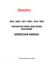 Hong Kong Easyweld Limited EasyArcZX7-300 Operating instructions
-
AUTO JACK DARC 140-160 User manual
-
 Autojack DARC-160 Owner's manual
-
frisco 216695 User manual
-
 Provo Craft YourStory LB30 User manual
-
aspenhome I430-402 Assembly Instructions


