Page is loading ...

For information on other great Peavey products, go to your local Peavey dealer or visit us online at www.peavey.com
Digital Effects Processor Owner's Manual
Dual DeltaFex
®

3
IMPORTANT SAFETY INSTRUCTIONS
WARNING: When using electrical products, basic cautions should always be followed, including the following:
1. Read these instructions.
2. Keep these instructions.
3. Heed all warnings.
4. Follow all instructions.
5. Do not use this apparatus near water.
6. Clean only with a dry cloth.
7. Do not block any of the ventilation openings. Install in accordance with manufacturer’s instructions.
8. Do not install near any heat sources such as radiators, heat registers, stoves or other apparatus (including amplifiers)
that produce heat.
9. Do not defeat the safety purpose of the polarized or grounding-type plug. A polarized plug has two blades with one
wider than the other. A grounding type plug has two blades and a third grounding plug. The wide blade or third prong is
provided for your safety. If the provided plug does not fit into your outlet, consult an electrician for replacement of the
obsolete outlet.
10. Protect the power cord from being walked on or pinched, particularly at plugs, convenience receptacles, and the point
they exit from the apparatus.
11. Only use attachments/accessories provided by the manufacturer.
12. Use only with a cart, stand, tripod, bracket, or table specified by the manufacturer, or sold with the apparatus. When a
cart is used, use caution when moving the cart/apparatus combination to avoid injury from tip-over.
13. Unplug this apparatus during lightning storms or when unused for long periods of time.
14. Refer all servicing to qualified service personnel. Servicing is required when the apparatus has been damaged in any
way, such as power-supply cord or plug is damaged, liquid has been spilled or objects have fallen into the apparatus,
the apparatus has been exposed to rain or moisture, does not operate normally, or has been dropped.
15. Never break off the ground pin. Write for our free booklet “Shock Hazard and Grounding.” Connect only to a power
supply of the type marked on the unit adjacent to the power supply cord.
16. If this product is to be mounted in an equipment rack, rear support should be provided.
17. Note for UK only: If the colors of the wires in the mains lead of this unit do not correspond with the terminals in your
plug‚ proceed as follows:
a) The wire that is colored green and yellow must be connected to the terminal that is marked by the letter E‚ the earth
symbol‚ colored green or colored green and yellow.
b) The wire that is colored blue must be connected to the terminal that is marked with the letter N or the color black.
c) The wire that is colored brown must be connected to the terminal that is marked with the letter L or the color red.
18. This electrical apparatus should not be exposed to dripping or splashing and care should be taken not to place objects
containing liquids, such as vases, upon the apparatus.
19. Exposure to extremely high noise levels may cause a permanent hearing loss. Individuals vary considerably in suscep
-
tibility to noise-induced hearing loss, but nearly everyone will lose some hearing if exposed to sufficiently intense noise
for a sufficient time. The U.S. Government’s Occupational Safety and Health Administration (OSHA) has specified the
following permissible noise level exposures:
Duration Per Day In Hours Sound Level dBA, Slow Response
8 90
6 92
4 95
3 97
2 100
1 1⁄2 102
1 105
1⁄2 110
1⁄4 or less 115
According to OSHA, any exposure in excess of the above permissible limits could result in some hearing loss. Ear plugs or protectors to
the ear canals or over the ears must be worn when operating this amplification system in order to prevent a permanent hearing loss, if
exposure is in excess of the limits as set forth above. To ensure against potentially dangerous exposure to high sound pressure levels, it is
recommended that all persons exposed to equipment capable of producing high sound pressure levels such as this amplification system be
protected by hearing protectors while this unit is in operation.
SAVE THESE INSTRUCTIONS!

7
Dual DeltaFex
®
Digital Effects Processor
Congratulations on your purchase of the Peavey Dual DeltaFex digital effects processor. You now have two programmable
effect engines that can be used in four different configurations. Each engine can have one of 16 effect types, making the Dual
DeltaFex useful for studios, P.A. systems or instrument processing.
CAUTION:
Use only the 16.5 volt power supply provided with this product. If the original power supply must be
replaced, consult your Peavey dealer or the factory for the correct replacement. Failure to use the correct power supply
could result in fire, shock hazard, extensive circuit damage, decreased performance or non-operation.
FEATURES:
• Intuitive interface for preset recalling, editing, and storing
• 200 presets (100 user/100 factory)
• 24-bit converters and processing
• 16 effect types, including reverbs, delays, modulations, distortion, karaoke, etc.
• Dual engines can be configured in series, parallel, dual mono or summed mono
• Four adjustments per effect (mix, param1, param2, level)
• Footswitch jack for effects defeat or rotary effect speed toggle
ENGLISH

8
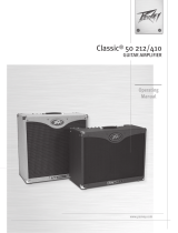
Power Button/LED (1)
Power (and LED) will be ON when switch is pushed in.
Input Level Control (2)
This knob attenuates or boosts the incoming signals (left and right). Set this so that the Signal/Clip
LED turns red only on extreme peaks (or not at all).
Signal/Clip LED (3)
This will illuminated green when either of the input signals reaches 18 dB under clipping. It will switch
to red when the level reaches 3 dB under clipping.
Output Level Control (4)
This knob controls the volume of the Left and Right outputs.
Store Button
(5)
Press this to enter Preset Store mode, which allows you to store the current effect settings. A
destination (00.-99.) can be selected, and a second “press” will store the data. (Pressing one of the
other buttons instead of a second press of Store will exit Store mode.)
Mode Button/LEDs
(6)
Pressing the Mode button will scroll through the top three LEDs (Preset mode, Edit A mode, Edit B
mode). Holding for one second will enter Defeat mode, after which a simple press will exit Defeat
mode.
Numerical Display/Data Wheel (7)
This is the main editing tool. The wheel allows editing of the parameter that is currently displayed,
indicated by the discrete LEDs.
Front Panel
1
2
4
3
5
6
Preset
Edit A
Edit B
Defeat
7
8
9

9
Edit Button/LEDs (8)
When in Edit A or Edit B mode, one of these LEDs (or all 4) will be illuminated, indicating which
parameter is active for editing. All will be OFF when not in Edit mode. (When all are ON, you will be
editing the output level for effect A or B.)
Configuration Button/LEDs (9)
These LEDs indicate the routing of two effect engines for the current preset – series, parallel, dual
mono or sum mono. Use the button to step through the choices.
Series Dual Mono
Parallel Sum Mono
8
9
Front Panel

10
Rear Panel
Rotary Speaker Speed/Defeat (1)
A momentary mono footswitch will allow effect defeat (bypass or mute) or rotary speed toggle. The
polarity of the footswitch will be sensed at power-up to allow normally closed or normally open types
without the need for a global parameter (so make sure the footswitch is connected before you power
up).
Audio Outputs (2)
These are Right and Left/Mono line-level outputs. Without a connection to the Right jack, the Left jack
will go into Mono mode. This will sum certain individual effects to mono, but it will not combine the
outputs of a preset with the dual mono configuration.
Audio Inputs (3)
These are Right and Left/Mono line-level inputs. Without a connection to the Right jack, the Left jack
will feed both sides.
Power (4)
Input for the 16 VAC, 1.1 amp power adapter.
NOTE: Use only Peavey part #70900660, which is a DV-1611A.
1
2
3
4

11
Operating Modes
Preset Recall Mode:
This is the default power-up mode. The Preset mode LED will be lit, the display will show the preset
number and the data wheel will scroll through presets. Setting the mode Select button to “Preset” will
put the unit into this mode at any time.
User Presets 00. - 99. will be shown first (with the decimal point lit), while fixed Factory Presets 00 - 99
will be shown next (without the decimal point lit).
Note: The unit can be re-initialized to factory default settings by holding STORE and MODE
while powering up. This will copy the Factory presets to the User presets, and initialize any
globals (like bypass vs. mute) to their default setting. You will see “in” on the display for a few
seconds while the unit restores its default setting.
A preset consists of: the settings for both effect engines (effect type, mix, parameters 1 & 2, level) and
the configuration (routing).
Store Mode:
Press the Store button to activate Store mode. The destination number will blink. If you are on a User
preset, the destination will initially be the same as the preset. If you are on a Factory preset, the default
destination will be the same preset number, but in the User bank. At this point, you have three options:
1. Press the Store button again to store into the current destination
2. Use the data wheel to choose a different location and then store
3. Press any other button to escape Store
Edit Mode:
Press the Select button to enter Edit A or Edit B mode. (Shortcut: pressing the EDIT button when in
Preset mode will also enter Edit A mode.) One of the four LEDs to the right of the display will light.
Once in Edit mode, the EDIT button will scroll down through five parameters (if the effect is not off): the
four shown next to each LED, and all LEDs on, indicating output level for effect A or B. At each stop the
display will show the value, and the data wheel can be used to edit it.
The parameter being edited/displayed belongs to either effect block A or B, indicated by the Mode
LEDs.
The CONFIG button will step through the four configurations (see page 9), which control how the two
effect engines are routed between the inputs and outputs for the current preset. Typically, you would
set this before editing the parameters, since it can (and most likely will) affect the overall sound – mix
ratios, depths, etc.

12
Operating Modes
Defeat Mode:
This mode can be entered via a momentary footswitch plugged into the DEFEAT jack on the rear of the
unit. It can also be entered by holding the MODE switch for a full second.
Defeat mode can be exited by another press of the footswitch, or a normal press of the MODE switch.
The display will read “by” when in Bypass mode, and “mu” when in Mute mode. To change which mode
is used, press the CONFIG button to alternate between them while in the Defeat mode. This is a global
setting that the unit will remember when powered down.
The data wheel can still be used to select presets while defeated. You will see the preset number for a
moment, after which the “by” or “mu” will return to the display. The preset will load inaudibly, so you
will hear it almost immediately when exiting defeat mode. If you need to simply see the current preset
number while defeated, press the EDIT button to see it for a couple seconds. The display will switch
back to “by” or “mu” automatically.
Bypass Mode:
In this mode, the left input will be routed to the left output, and the right input will be routed to the
right output (the input and output level knobs will still be active – it’s not a hard-wired bypass). Use this
mode when the unit is in a serial-type loop, such as a guitar amp’s effects loop, between a mixer and
amplifier, etc.
Mute Mode:
When in this mode, the outputs will be muted. Use this mode when the unit is in a parallel loop, like
a mixer’s aux send, etc. If used in series with an instrument or as a channel insert, it will disable the
channel.
Editing tip:
Choose Bypass or Mute prior to editing presets. The default mix parameters will be
99 (100%) when in Mute mode – saving you time from having to set them there.

13
Edit Parameters
Effect:
This is the Effect Type currently assigned to the engine. The 16 types are listed on the front panel. You
can also edit below 1 to turn the engine off (shown as “--”). You can assign any effect to either engine
– even the same effect in both.
Mix:
Most of the effects (all except Compressor and Tremolo) have a wet/dry mix (adjustable when the MIX
LED is lit). 00 is fully dry, 50 is equal amounts of wet and dry and 99 is fully wet. When using in an aux
send (P.A. or studio), set the mix to 99 to get an “all effect” feed to the aux return or channel. When
used in the effects loop of a guitar amp, increasing mix levels from 0 to 50 will result in more audible
effect while still hearing plenty of dry sound.
Level:
All of the effects have an output level that is adjustable when all four EDIT LEDs are lit. When used in
parallel, this is useful to balance the outputs. In series configuration, engine B’s level is basically a
programmable preset level, while engine A’s level can be used to control the level driving engine B.
Output level range is:
0-99 – 0-100% (20% audio taper)
b1- b6 – Boosted by 1 dB - 6 dB
Parameters 1 and 2:
These parameter names are listed on the front of the unit for convenience. The descriptions of these for
each effect type are below.
1 Plate Reverb
2 Hall Reverb
3 Room Reverb
These effects simulate different reverberant spaces by creating dense layers of echoes. Plate is a
popular electronic reverb type, while Hall and Room are designed to simulate those environments.
Parameter 1 (Time) – Reverberation time – from 1 second up to 10 seconds. There are half-second
intervals near the bottom of the range, then 1 second intervals for the remainder.
Parameter 2 (Color) – This provides a way to make the reverb darker sounding via a high-cut filter.
The settings (in kHz.) are 1, 2, 4, 8, and “br” for bright, which disables the filter.

14
Edit Parameters
4 Short Delay
5 Bright Delay
6 Dark Delay
The delay effects create discrete echoes. The short delay can be used to really fine tune a short
duration, or extremely short and mixed with the dry for a fixed comb filter (flange) effect. The Bright
Delay is a longer delay. The Dark Delay is also long, but cuts a significant amount of treble from the
wet signal to simulate vintage tape and analog echo units.
Parameter 1 (Time) – Delay time from 1 to 99 ms. on the Short delay, and 10 ms. to 1.4 seconds on
the Bright and Dark delays.
For the Bright and Dark (long) Delays, the display will read as follows:
10 – 90 – 10-90 ms.
10. – 99. – 100-990 ms. (picture a “zero” on the right instead of the decimal)
0.0. – 4.1. – 1.00-1.41 seconds (picture a “1” on the left instead of the decimals)
Parameter 2 (Feedback) – The amount of delay output that is fed back to the delay input, resulting
in more echoes being repeated. Range is 0% to 99%.
7 Pitch Shifter
This effect can be used totally wet (mix=99) to bring an instrument down a half step or more, or
mixed with the dry sound to create a harmonized (using Steps) or detuned (using Fine) effect.
Parameter 1 (Steps) – This sets the coarse shift amount in semi-tones. Range is +/- 12.
Parameter 2 (Fine) – This will fine-tune the amount of pitch shift in between semitones. It’s useful
when Steps is zero and mixed with the dry sound for a detuning effect. Range is +/-9.
Tip:
When using two pitch shifters in parallel, it can be useful to mix them both fully wet with
equal steps, but detune one slightly for some extra thickness.
8 Compressor
The Compressor effect reduces high signal levels and boosts small signal levels. The net result is a
more consistent output volume and increased sustain.
Parameter 1 (Sustain) – This sets the maximum amount of gain that the compressor can use to
amplify the signal up to the Limit level. It can be thought of as an intelligent drive control. Range is
0 to 6.
Parameter 2 (Limit) – This sets the maximum level that the compressor will allow on the
output (even though transient peaks may exceed it for a short time since the attack time isn’t
instantaneous). Lower values will result in more apparent compression (which can be made up for
with the output level). Range is 0% to 99%.

15
Edit Parameters
9 Chorus
10 Flanger
11 Phaser
12 Tremolo
These are the standard modulation effects. The chorus modulates a left and right delay to create
a detuned doubling. The flanger uses a shorter delay and feedback to create a modulated comb
filter. The phaser uses modulated all-pass filters to create a different type of swept comb filter. The
tremolo effect is the traditional amplitude-modulated effect.
Parameter 1 (Speed) – Rate of modulation, 0-99%.
Parameter 2 (Depth) – Intensity (width) of modulation, 0-99%.
13 Rotary
This effect simulates a two-way rotary speaker cabinet popular with organists (but is very useful
on guitar and other signals). The signal is split into low and high frequencies and modulated
separately and at slightly different speeds.
Parameter 1 (Speed) – Rate of modulation, 0-99%. Pressing the footswitch will allow you to toggle
between two speeds, and you can set these low and high speeds however you want. (One of the
speeds will be shown with the decimal point, and the other without.) The Rotary effect will ramp
the speed between these values, just like a real rotating speaker.
If you want the footswitch to still act as a defeat, set either speed to “oF” for off, and the Dual
DeltaFex
®
will enter Defeat (Bypass/Mute) mode instead of toggling the speed. (When editing
Rotary, pressing the footswitch will always toggle the speed values to allow you to change the “oF”
back to a real speed value.)
Parameter 2 (Depth) – Intensity (width) of modulation, 0-99%.
14 Distortion
The Distortion effect consists of a digital distortion followed by a tone section, then an optional
speaker simulator for full-range systems (which removes a lot of the treble frequencies that a
typical guitar cabinet does not reproduce). This effect does have a mix, which is something you
don’t get with most distortion devices.
Tip:
Experiment with running some dry sound along with the distortion to regain some note
definition.
Parameter 1 (Drive) – The amount of gain, or distortion amount. Range: off, 0-10 (choose off to
bypass the distortion and use the tone and speaker simulator by themselves).
Parameter 2 (Tone) – This cuts high end as you turn it down, like a tone knob on a distortion pedal.
Range: 00 - 99 (non-cab simulated), then 00. - 99. (cab simulated).

16
Edit Parameters
15 Exciter
The Exciter effect adds harmonics as an enhancement to the dry signal. A popular use is to add a
high-end “sheen” to vocals, acoustic guitars, etc.
Parameter 1 (Drive) – The amount of gain into the exciter, 0-99%. Higher gains produce more
harmonics.
Parameter 2 (Frequency) – This controls the frequency of a low-cut filter preceding the exciter,
allowing it to generate harmonics based on the higher frequencies.
16 Karaoke
This is a vocal removal effect that cancels any audio (above the crossover point) that is mixed down
the center of the stereo field. Lead vocals are usually mixed this way, whereas instruments (and
some background vocals) are usually panned away from center or stereo-mixed in other ways.
Vocals mixed to center often have stereo effects added to them, so you will hear only the effects in
many cases.
Note:
Due to the nature of this effect, it will only work correctly under the following
circumstances:
• Engine A in series mode (typical usage), or Engine B if Engine A is off
• Engine A or B in parallel mode with the other engine off (muted)
Parameter 1 (Crossover) – Frequencies lower than this point will not be canceled. Bass and kick
drum are popular choices for mixing down the center, and the goal is for that low end to still be
audible. Increase it for more bass, decrease for more cancellation on low-pitched vocals. Range is
100 Hz –190 Hz (display shows 0.0. – 9.0.).
Parameter 2 (Pan) – This will control the balance between the left/right mix (treble side, after the
crossover). This could be used to get less cancellation when wanted, or get more cancellation in
cases where the vocal may be slightly panned (or the source left and right signals are not the same
exact level). Range is +/- 9 (default is 0).
Tip:
What happens if you drive a mono signal into this effect? Interestingly enough, it acts as
a drastic midrange scoop. Raising the Crossover point will increase the bass, and moving the
Cancel Amt away from zero will increase the midrange. There is usually a substantial volume
loss, but the output level can add 6 dB, and the other effect block can add more if used in
series. Factory presets 71 and 81 use the Karaoke effect as a mid scoop for guitar.

17
Factory Preset List
The following page shows the mapping for the 100 factory presets. These presets are always available
as 00-99 (without the decimal point), and also reside in the user presets when the unit is initialized
from the factory.
Presets 00 to 49 are designed for mixer aux sends and parallel effects loops (where the audio from the
Dual DeltaFex
®
is adding to the already audible dry sound). Most mix settings will be full. These are
typically used with the defeat mode set to Mute.
Presets 50 to 99 are designed for series-type applications (guitar amp serial effects loops, between
guitar and amp, between CD player and mixer, etc.) Mix parameters are generally set for the dry sound
to come through the unit with the effected sound added to it. These are typically used with the Defeat
mode set to Bypass.

18
Factory Preset List
00-49 – Parallel effects (mixer aux send, parallel effects loop, etc.) Use Mute mode for defeat footswitch.
Reverbs Delays Ambience
(reverb/delay combos)
Enhancement Combos
00 Normal Plate 10 Short slap 20 Bright Delay Hall 30 Exciter 40 Plate Chorus
(Chorused reverb tail)
01 Long Plate 11 Short slap with feedback 21 Short Delay Plate 31 Distortion
41 Hall Phaser
(Phased reverb tail)
02 Normal Hall 12 Bright echo short 22 Dark Delay + Plate 32 Chorus 42 Exciter Plate
03 Long Hall 13 Bright echo medium 23 Short Delay + Room
33 Chorus + Chorus 43 Pitch Shifter + Chorus
04 Room
14 Bright echo long 24 Bright Delay | Hall 34 Flanger 44 Distortion Bright Delay
05 Plate with 100ms Predelay 15 Dark echo short
25 Dark Delay | Plate 35 Phaser 45 Chorus | Plate
06 Hall with 250ms Predelay
16 Dark echo medium 26 Short Delay | Room 36 Pitch Shifter (detune) 46 Exciter | Room
07 Room left / Plate right 17 Dark echo long
27 Bright Delay / Hall 37 Rotary + Chorus 47 Rotary | Hall
08 Room left | Plate right 18 Short left / Dark right 28 Dark Delay / Plate 38 Exciter | Chorus
48 Pitch Shifter / Plate
09 Plate + Hall 19 Bright left | Dark right 29 Short Delay / Room 39 Chorus / Flanger 49 Exciter / Hall
50-99 – Series effects (series effects loop, between instrument and amp, etc.) Use Bypass mode for defeat footswitch.
Modulation Series effects
(Guitar amp effects loop, etc.)
Preamp
(Between Guitar and amp, etc.)
Preamp Direct
(Between guitar and PA/full range)
Pedal Steel
50 Chorus 60 Plate Reverb 70 Compressor 80 Cabinet Simulator
(treble roll off / tweeter filter)
90 Plate Reverb
51 Chorus + Chorus 61 Dark Delay 71 Distortion Karaoke
(mid scoop)
81 Distortion Karaoke
(mid scoop)
91 Slap Delay Room
52 Chorus + Pitch Shifter
(detune)
62 Dark Delay Plate
72 Compressor
Distortion
82 Compressor Distortion 92 Rotary Room
53 Flanger 63 Short Delay + Room 73 Distortion Plate 83 Distortion Plate 93 Chorus Plate
54 Flanger + Chorus 64 Bright Delay Hall 74 Distortion Dark Delay 84 Distortion Dark Delay 94 Distortion Dark Delay
55 Phaser 65 Pitch Shifter + Pitch Shifter
(harmonized)
75 Distortion Chorus 85 Distortion Chorus
Karaoke
(vocal eliminator)
56 Tremolo 66 Tremolo Hall 76 Distortion Phaser 86 Distortion Phaser 95 Karaoke 2 notes down
57 Phaser Tremolo 67 Pitch Shifter (E-flat) 77 Distortion Tremolo 87 Distortion Tremolo 96 Karaoke 1 note down
58 Rotary 68 Rotary Plate 78 Distortion Rotary 88 Distortion Rotary 97 Karaoke
59 Rotary + Chorus
69 Phaser Dark Delay 79 Distortion
Pitch Shifter
89 Distortion Pitch Shifter 98 Karaoke 1 note up
99 Karaoke 2 notes up
Configuration notation: series + parallel | dual mono / sum mono

19
Dual DeltaFex
®
Digital Effects Processor
SPECIFICATIONS
Frequency Response:
20 Hz - 20 kHz
A/D and D/A Conversion:
Rate: 44.1 kHz
Quantization: 24 bit
Signal-to-noise ratio:
98 dB (unweighted) minimum
THD: Less than .005 %
Inputs:
Left, right: -12 dBv nominal
+18 dBv maximum
Impedance: 100k ohm
Outputs:
Left, right: +12 dBV maximum
Impedance: 1k ohm
Headroom:
Clip indication at 3 dB before clipping
Presets:
100 user/100 factory
Power Requirement:
External 16 VAC, 1.1 amp Power Supply
(Peavey #70900660)
Dimensions:
1.75” H x 19.00” W x 8.00” D
(4.44 cm x 48.26 cm x 20.32 cm)
Weight:
6.2 lbs. (2.8 kg) with power supply
5.1 lbs. (2.3 kg) without power supply

31
Anmerkung zur Konfiguration
00-49 – Parallele Effekte (Mixer Aux Send, parallele Effektschleife usw.). Der Fußschalter wird über den Mute-Modus deaktiviert.
Reverbs Delays Ambience
(reverb/delay combos)
Enhancement Combos
00 Normal Plate 10 Short slap 20 Bright Delay Hall 30 Exciter 40 Plate Chorus
(Chorused-Reverb-Ende)
01 Long Plate 11 Short slap with feedback 21 Short Delay Plate 31 Distortion 41 Hall Phaser
(Phased-Reverb-Ende)
02 Normal Hall 12 Bright echo short 22 Dark Delay + Plate 32 Chorus 42 Exciter Plate
03 Long Hall 13 Bright echo medium 23 Short Delay + Room
33 Chorus + Chorus 43 Pitch Shifter + Chorus
04 Room
14 Bright echo long 24 Bright Delay | Hall 34 Flanger 44 Distortion Bright Delay
05 Plate with 100ms Predelay 15 Dark echo short
25 Dark Delay | Plate 35 Phaser 45 Chorus | Plate
06 Hall with 250ms Predelay
16 Dark echo medium 26 Short Delay | Room 36 Pitch Shifter (detune) 46 Exciter | Room
07 Room left / Plate right 17 Dark echo long
27 Bright Delay / Hall 37 Rotary + Chorus 47 Rotary | Hall
08 Room left | Plate right 18 Short left / Dark right 28 Dark Delay / Plate 38 Exciter | Chorus
48 Pitch Shifter / Plate
09 Plate + Hall 19 Bright left | Dark right 29 Short Delay / Room 39 Chorus / Flanger 49 Exciter / Hall
50-99 – Hintereinander geschaltete Effekte (hintereinander geschaltete Effektschleife, zwischen Instrument und Verstärker usw.). Der Fußschalter wird über den Bypass-Modus
deaktiviert.
Modulation Series effects
(Effektschleife eines Gitarrenverstärkers
usw.)
Preamp
(Zwischen Gitarre und Verstärker usw.)
Preamp Direct
(Zwischen Gitarre und PA/Fullrange)
Pedal Steel
50 Chorus 60 Plate Reverb 70 Compressor 80 Cabinet Simulator
(Dämpfen der Höhen/Tweeter-Filter)
90 Plate Reverb
51 Chorus + Chorus 61 Dark Delay 71 Distortion Karaoke
(Mittenverstärker)
81 Distortion Karaoke
(Mittenverstärker)
)
91 Slap Delay Room
52 Chorus + Pitch Shifter
(detune)
62 Dark Delay Plate
72 Compressor
Distortion
82 Compressor Distortion 92 Rotary Room
53 Flanger 63 Short Delay + Room 73 Distortion Plate 83 Distortion Plate 93 Chorus Plate
54 Flanger + Chorus 64 Bright Delay Hall 74 Distortion Dark Delay 84 Distortion Dark Delay 94 Distortion Dark Delay
55 Phaser 65 Pitch Shifter + Pitch Shifter
(harmonisiert)
75 Distortion Chorus 85 Distortion Chorus
Karaoke
(Vokal-Eliminator)
56 Tremolo 66 Tremolo Hall 76 Distortion Phaser 86 Distortion Phaser 95 Karaoke 2 notes down
57 Phaser Tremolo 67 Pitch Shifter
(Es) 77 Distortion Tremolo 87 Distortion Tremolo 96 Karaoke 1 note down
58 Rotary 68 Rotary Plate 78 Distortion Rotary 88 Distortion Rotary 97 Karaoke
59 Rotary + Chorus
69 Phaser Dark Delay 79 Distortion
Pitch Shifter
89 Distortion Pitch Shifter 98 Karaoke 1 note up
99 Karaoke 2 notes up
Anmerkung zur Konfiguration: Reihe + parallel | dual mono / sum mono

44
Presets d’usine
00-49 – Effets parallèles (envoi aux mixeur,boucle d’effet parallèle.) utiliser le mode mute pour actionner le defaet avec un footswitch
Réverbérations Délais Ambiances Embellisseurs Combinaisons
00 Normal Plate 10 Court 20 Délai clair Hall 30 Exciteur 40 Plate Chorus
(Chorused reverb tail)
01 Longue plate 11 Court avec retard 21 Délai court Plate 31 Distortion
41 Hall Phaser
02 Hall normal 12 Court clair écho 22 Délai sombre + plate 32 Chorus 42 Exciter Plate
03 Hall long 13 Clair écho moyen 23 Délai court + room
33 Chorus + Chorus 43 Désaccordeur + Chorus
04 Pièce 14 Clair écho long 24 Délai clair | Hall 34 Flanger 44 Distortion Délai clair
05 Plate avec préretard de
100ms
15 Sombre écho court 25 Délai sombre | Plate
35 Phaser 45 Chorus | Plate
06 Hall avec préretard
de 250ms
16 Sombre écho moyen 26 Délai court | room 36 transposition d’octave
(désaccordeur)
46 Exciter | Room
07 Pièce gauche/ Plate droite 17 Sombre écho long
27 Délai clair long 37 Rotary + Chorus 47 Rotary | Hall
08 Pièce gauche|Plate droite 18 Court gauche/ Sombre
droite
28 Délai sombre/ Plate 38 Exciter | Chorus 48 Transposeur/Plate
09 Plate + Hall 19 Clair gauche | Sombre
droite
29 Délai court / Pièce 39 Chorus/Flanger 49 Embellisseur/Hall
50-99 –Effet mode serie (boucle d’effet en serie pour un amplificateur de guitare, entre un guitare et un amplificateur, entre un platine de CD et un mixeur, etc)
Modulation Effet de serie Preamp Preamp direct Pedal Steel
50 Chorus 60 Réverbération plate 70 Compresseur 80 Simulateur d’enceinte 90 Réverbération plate
51 Chorus + Chorus 61 Délai sombre 71 Distortion Karaoké 81 Distortion Karaoké 91 Délai pièce
52 Chorus + Transposeur 62 Délai sombre Plate 72 Compresseur
Distortion
82 Compresseur
distortion
92 Rotary Pièce
53 Flanger 63 Délai court + pièce 73 Distortion Plate 83 Distorion Plate 93 Chorus Plate
54 Flanger + Chorus 64 Délai clair Hall 74 Distortion Délai
sombre
84 Distortion Délai
sombre
94 Distortion Délai sombre
55 Phaser 65 Transposeur + Transposeur 75 Distortion Chorus 85 Distortion Chorus Karaoke (eliminateur de voix)
56 Tremolo 66 Tremolo Hall 76 Distortion Phaser 86 Distortion Phaser 95 Karaoke 2notes en dessous
57 Phaser Tremolo 67 Transposeur 77 Distortion Tremolo 87 Distortion Tremolo 96Karaoke 1 note en dessous
58 Rotary 68 Rotary Plate 78 Distortion Rotary 88 Distortion Rotary 97 Karaoke
59 Rotary + Chorus 69 Phaser Delay sombre 79 Distortion
Transposeur
89 Distortion Transposeur 98 Karaoke 1 note en dessus
99 Karaoke 2 note en dessus
Notation des configurations: series + parallèle | double mono / somme mono

59
PEAVEY ELECTRONICS CORPORATION LIMITED WARRANTY
Effective Date: July 1, 1998
What This Warranty Covers
Your Peavey Warranty covers defects in material and workmanship in Peavey products purchased and serviced in the U.S.A. and Canada.
What This Warranty Does Not Cover
The Warranty does not cover: (1) damage caused by accident, misuse, abuse, improper installation or operation, rental, product modification or neglect; (2) dam
-
age occurring during shipment; (3) damage caused by repair or service performed by persons not authorized by Peavey; (4) products on which the serial number
has been altered, defaced or removed; (5) products not purchased from an Authorized Peavey Dealer.
Who This Warranty Protects
This Warranty protects only the original retail purchaser of the product.
How Long This Warranty Lasts
The Warranty begins on the date of purchase by the original retail purchaser. The duration of the Warranty is as follows:
Product Category Duration
Guitars/Basses, Amplifiers, Pre-Amplifiers, Mixers, Electronic
Crossovers and Equalizers 2 years *(+ 3 years)
Drums 2 years *(+ 1 year)
Enclosures 3 years *(+ 2 years)
Digital Effect Devices and Keyboard and MIDI Controllers 1 year *(+ 1 year)
Microphones 2 years
Speaker Components (incl. speakers, baskets, drivers,
diaphragm replacement kits and passive crossovers)
and all Accessories 1 year
Tubes and Meters 90 days
[*Denotes additional warranty period applicable if optional Warranty Registration Card is completed and returned to Peavey by original retail purchaser within 90 days of pur-
chase.]
What Peavey Will Do
We will repair or replace (at Peavey's discretion) products covered by warranty at no charge for labor or materials. If the product or component must be shipped to
Peavey for warranty service, the consumer must pay initial shipping charges. If the repairs are covered by warranty, Peavey will pay the return shipping charges.
How To Get Warranty Service
(1) Take the defective item and your sales receipt or other proof of date of purchase to your Authorized Peavey Dealer or Authorized Peavey Service Center.
OR
(2) Ship the defective item, prepaid, to Peavey Electronics Corporation, International Service Center, 412 Highway 11 & 80 East, Meridian, MS 39301 or Peavey
Canada Ltd., 95 Shields Court, Markham, Ontario, Canada L3R 9T5. Include a detailed description of the problem, together with a copy of your sales receipt or
other proof of date of purchase as evidence of warranty coverage. Also provide a complete return address.
Limitation of Implied Warranties
ANY IMPLIED WARRANTIES, INCLUDING WARRANTIES OF MERCHANTABILITY AND FITNESS FOR A PARTICULAR PURPOSE, ARE LIMITED IN DURATION TO THE
LENGTH OF THIS WARRANTY.
Some states do not allow limitations on how long an implied warranty lasts, so the above limitation may not apply to you.
Exclusions of Damages
PEAVEY'S LIABILITY FOR ANY DEFECTIVE PRODUCT IS LIMITED TO THE REPAIR OR REPLACEMENT OF THE PRODUCT, AT PEAVEY'S OPTION. IF WE ELECT TO
REPLACE THE PRODUCT, THE REPLACEMENT MAY BE A RECONDITIONED UNIT. PEAVEY SHALL NOT BE LIABLE FOR DAMAGES BASED ON INCONVENIENCE, LOSS OF
USE, LOST PROFITS, LOST SAVINGS, DAMAGE TO ANY OTHER EQUIPMENT OR OTHER ITEMS AT THE SITE OF USE, OR ANY OTHER DAMAGES WHETHER INCIDENTAL,
CONSEQUENTIAL OR OTHERWISE, EVEN IF PEAVEY HAS BEEN ADVISED OF THE POSSIBILITY OF SUCH DAMAGES.
Some states do not allow the exclusion or limitation of incidental or consequential damages, so the above limitation or exclusion may not apply to you.
This Warranty gives you specific legal rights, and you may also have other rights which vary from state to state.
If you have any questions about this warranty or service received or if you need assistance in locating an Authorized Service Center, please contact the Peavey
International Service Center at (601) 483-5365 / Peavey Canada Ltd. at (905) 475-2578.
Features and specifications subject to change without notice.
Logo referenced in Directive 2002/96/EC Annex IV
(OJ(L)37/38,13.02.03 and defined in EN 50419: 2005
The bar is the symbol for marking of new waste and
is applied only to equipment manufactured after
13 August 2005

Features and specifications subject to change without notice.
Peavey Electronics Corporation • 711 A Street • Meridian, MS 39301
(601) 483-5365 • FAX (601) 486-1278 • www.peavey.com
EX000012
© 2005
/