Page is loading ...

DR
®
FIELD and BRUSH MOWER
SAFETY & OPERATING INSTRUCTIONS
Serial No.
Order No.
DR Power Equipment
Toll-free phone: 1-800-DR-OWNER (376-9637)
Fax: 1-802-877-1213
Website: www.DRpower.com
Read and understand this manual and all instructions before operating the DR FIELD and BRUSH MOWER.
Original Language
Models:
10.5HP PRO-26
14.5HP PRO-26
16.5HP PRO XL 30
20.0HP PRO XL30
20.0HP PRO MAX

2 DR
®
FIELD and BRUSH MOWER

CONTACT US AT www.DRpower.com 3
Table of Contents
Chapter 1: General Safety Rules ............................................................................................................................................................ 4
Chapter 2: Setting Up the DR FIELD and BRUSH MOWER ................................................................................................................ 8
Chapter 3: Operating the DR FIELD and BRUSH MOWER ................................................................................................................. 13
Chapter 4: Maintaining the DR FIELD and BRUSH MOWER .............................................................................................................. 18
Chapter 5: Troubleshooting .................................................................................................................................................................. 24
Chapter 6: Parts Lists, Schematic Diagrams and Warranty ................................................................................................................. 26
Conventions used in this manual
Serial Number and Order Number
A Serial Number is used to identify your machine and is located on the Serial
Number Label on your machine (Figure 1). An Order Number is used to check
and maintain your order history and is located on your packing slip. For your
convenience and ready reference, enter the Serial Number and Order Number in
the space provided on the front cover of this manual.
Additional Information and Potential Changes
DR Power Equipment reserves the right to discontinue, change, and improve its
products at any time without notice or obligation to the purchaser. The
descriptions and specifications contained in this manual were in effect at
printing. Equipment described within this manual may be optional. Some
illustrations may not be applicable to your machine.
This indicates a hazardous situation, which, if not avoided, could result in death or serious injury.
This indicates a hazardous situation, which, if not avoided, could
result in minor or moderate in
j
ur
y
.
This information is important in the proper use of your machine. Failure to follow this instruction could result in damage
to
y
our machine or
p
ro
p
ert
y
.
Figure 1
Serial Number Label

4 DR
®
FIELD and BRUSH MOWER
Chapter 1: General Safety Rules
Labels
The DR FIELD and BRUSH MOWER carries prominent labels as reminders for its proper and safe use. Shown below are copies of
all the Safety and Information labels that appear on the equipment. Take a moment to study them and make a note of their
location on your mower as you set up and before you operate the unit. Replace damaged or missing safety and information labels
immediately.
Warnings, Cautions, and Notices
General Safety
Read this safety & operating instructions manual before you use the DR FIELD and BRUSH MOWER. Become familiar with the
operation and service recommendations to ensure the best performance from your machine. If you have any questions or need
assistance, please contact us at www.DRpower.com or call toll-free 1-800-DR-OWNER (376-9637) and one of our Technical
Support Representatives will be happy to help you.
Safe operation of the DR FIELD and BRUSH MOWER is necessary to prevent death or serious injury. Always take the following
precautions when operating this machine:
The DR FIELD and BRUSH MOWER is designed to mow grass and brush. Do not use it for any other purpose.
If the machine makes an unusual noise or vibration or if there are obstructions underneath the machine, shut off the DR
FIELD and BRUSH MOWER engine. Wait five minutes for the engine to cool. Disconnect the spark plug wire(s) and then
inspect the machine for clogs or loose parts. Clear any obstructions and repair and/or replace damaged parts.
The mower blades are sharp. Wrap the blades or wear gloves and use extra caution when servicing.
Always keep the machine in good, safe operating condition. Always make certain nuts and bolts are tight. Do not use
substitute hardware.
See manufacturer’s instructions for proper operation and installation of accessories. Only use accessories approved by DR
Power Equipment.
#
36373
#37045
#35276
#36372
#
13758
#
13683
#13649

CONTACT US AT www.DRpower.com 5
General Safety (Continued)
Protecting Yourself and Those around You
Slope Operation
Slopes are a major factor related to slip and fall accidents. All slopes require caution. If you feel uneasy on a slope, do not mow it.
Always take the following precautions when using this machine on slopes:
Always mow across the face of slopes. Exercise extreme caution when changing direction on slopes.
Never operate near drop-offs, ditches, or embankments, or on slopes greater than 20 degrees
Never operate on wet or slippery slopes.
This is a high-powered machine with moving parts operating at high speeds. Always take the following precautions when
operating this machine:
Always wear protective goggles or safety glasses with side shields.
Wear sturdy shoes with non-slip treads.
Wear long pants while operating the mower.
Avoid wearing loose clothing or jewelry which can catch on moving parts
Use ear protectors or ear plugs.
We recommend wearing gloves while mowing. Be sure your gloves fit properly and do not have loose cuffs or drawstrings.
Allow only responsible adults who are familiar with these safety rules and operating instructions to use your DR FIELD and
BRUSH MOWER.
Keep your hands and feet away from the blades, belt, pulley, and concealed areas while the engine is running.
Keep people and pets away from your machine and out of the work area at all times. Disengage the blade and stop the engine
if a person or pet is within 100 feet of the machine.
Children are often attracted to the machine and the mowing activity. Never assume that children will remain where you last
saw them.
Never allow people to ride on the mower.
Before mowing, clear the area of objects such as rocks, toys, wire, bones, sticks, etc.
Never remove or alter standard parts or add anything to the DR FIELD and BRUSH MOWER especially all shields and guards.
Before and while moving backwards, look behind, and down, for small children.
Use extra care when approaching blind corners, shrubs, trees, or other objects that may obscure your vision.
Use caution when mowing close to fences, buildings, and trees so as not to hit the handle bar. You could injure your hand or
lose control of the machine.
Use the DR FIELD and BRUSH MOWER only in daylight or very well lit work areas.
Be sure all blade and wheel controls are disengaged before attempting to start the engine. Engage and disengage the blade a
few times to get used to it before mowing.
Always give undivided attention to the machine and your surroundings. Watch for traffic when mowing near roadways.
Disengage the mower blades and exercise extreme caution when on or crossing drives, walks, or roads.
In an emergency, to quickly stop the cutting blade and shut off the engine, remove your hand from the operator presence
lever on the left handlebar.
Always shut off the engine whenever you leave the machine.
When operating over uneven and/or slippery terrain, use extreme caution to ensure solid and firm footing. Keep a firm hold
on the handlebars and walk, never run.
Do not operate the machine when under the influence of drugs, alcohol, or medication.

6 DR
®
FIELD and BRUSH MOWER
California Proposition 65:
Engine exhaust and some of its constituents are known to the state of California to cause cancer, birth defects, and other
reproductive harm.
This product contains or emits chemicals known to the state of California to cause cancer, birth defects, and other
reproductive harm.
Safety with Gasoline - Powered Machines
California Proposition 65
A Note to All Users
Under California law, and the laws of some other states, you are not permitted to operate an internal combustion engine using
hydrocarbon fuels without an engine spark arrester. This also applies to operation on US Forest Lands. All DR
®
FIELD and
BRUSH MOWERS shipped to California, New Mexico and Washington State are provided with spark arresters. Failure of the
owner or operator to maintain this equipment in compliance with state regulations is a misdemeanor under California law and
may be in violation of other state and/or federal regulations. Contact your appropriate local or state organization for specific
information in your area.
No list of warnings and cautions can be all-inclusive. If situations occur that are not covered by this manual, the operator must
apply common sense and operate this DR FIELD and BRUSH MOWER in a safe manner. Contact us at www.DRpower.com or call
1-800-DR-OWNER (376-9637) for assistance.
Gasoline is a highly flammable liquid that gives off flammable vapor that can be ignited and cause a fire or explosion. Always
follow these precautions:
Never run the engine in an enclosed area or without proper ventilation as the exhaust contains carbon monoxide, an odorless,
tasteless, and poisonous gas.
Store all fuel and oil in containers specifically designed and approved for this purpose. Keep away from heat and open flame
and out of the reach of children.
Replace rubber fuel lines and grommets when worn or damaged or after 5 years of use, whichever comes first.
Fill the gasoline tank outdoors with the engine off and after the engine has cooled completely. Do not handle gasoline if you
or anyone nearby is smoking.
If you spill gasoline do not start the engine. Move the machine away from the area until the gas vapors have dissipated.
Before performing engine maintenance or repairs; shut down the engine, disconnect the spark plug wire(s), and wait 5
minutes for the engine to cool.
Never change the engine governor settings or modify the engine speed.
Never check for an ignition spark with the spark plug or spark plug wire(s) removed. Always use an approved spark tester.
Never tamper with safety devices. Regularly check their proper operation.
Allow the engine to cool completely before storing in any enclosed area.
Keep combustible substances away from the engine when it is hot. Never cover the machine while the muffler is still hot.
To reduce fire hazard, keep the engine and muffler free of debris build-up.
Do not operate the engine with the air cleaner or the carburetor air intake cover removed.
Do not use flammable solutions to clean the air filter.
Never operate the engine without the muffler and deflector, if so equipped. Inspect the muffler and deflector periodically and
replace if necessary.
Themufflerandenginebecomevery hotandcancauseasevereburn.Donottouch.

CONTACT US AT www.DRpower.com 7

8 DR
®
FIELD and BRUSH MOWER
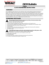
20 hp Shown (14.5
hp and 16.5 hp
Engines Similar)
Muffler
Oil Filter
Right
Brake/Steering
Lever
Fuel Fill
Belt Guard
Traction
Drive
Lever
Operator Presence
Control Lever
Throttle Lever
Key
Switch
PTO Knob
(Blade On/Off)
Wheel Speed
Leve
r
Control Pane
l
Chapter 2: Setting Up the DR FIELD and BRUSH MOWER
It may be helpful to familiarize yourself with the controls and features of your DR FIELD and BRUSH MOWER as shown in Figure
2 before beginning these procedures. If you have any questions at all, please feel free to contact us at www.DRpower.com.
DR FIELD and BRUSH MOWER Controls and Features
10.5
h
p
En
g
ine
Muffler
Fuel Fill
Pull Start
Handle
Left
Brake/Steering
Lever
Fuel Shut-O
ff
Valve
ON
Fuel Tan
k
Brush Bar
Brush Blade
(Under Deck)
Brush Deck
Fuel Filter
Oil Fill/
Dipstick
Oil Drain
Figure 2

CONTACT US AT www.DRpower.com 9
OFF
Specifications
10.5 HP PRO-26 14.5 HP PRO-26 16.5 HP PRO XL 30 20.0 HP PRO XL30 20.0 HP PRO MAX 34
Engine See Engine Owner’s
Manual
See Engine Owner’s
Manual
See Engine Owner’s
Manual
See Engine Owner’s
Manual
See Engine Owner’s
Manual
Fuel Capacity 3 Quarts 2 Gal. (7.57 L) 2 Gal. (7.57 L) 2 Gal. (7.57 L) 2 Gal. (7.57 L)
Cutting Capacity
4' Tall Grass
8' Tall Brush
2" Thick Saplings
4' Tall Grass
8' Tall Brush
2-1/2" Thick Saplings
6' Tall Grass
8' Tall Brush
2-1/2" Thick Saplings
6' Tall Grass
8' Tall Brush
3" Thick Saplings
6' Tall Grass
8' Tall Brush
3" Thick Saplings
Cutting Width 26" 26" 30" 30" 34"
Cutting Height 4" 4" 4" 4" 4"
Speeds
3 Forward
1 Reverse
3 Forward
1 Reverse
3 Forward
1 Reverse
3 Forward
1 Reverse
3 Forward
1 Reverse
Power Steering
No No Yes Yes Yes
Tires
18" x 6-1/2" x 8"
All Terrain
Sealant Filled
18" x 6-1/2" x 8"
All Terrain
Sealant Filled
18" x 6-1/2" x 8"
All Terrain
Sealant Filled
18" x 6-1/2" x 8"
All Terrain
Sealant Filled
18" x 6-1/2" x 8"
All Terrain
Sealant Filled
Machine
Dimensions
80.5” L
30.25” W
48.2” H
80.5” L
30.25” W
48.2” H
83” L
33” W
48.2” H
83” L
33” W
48.2” H
84.5” L
38” W
48.2” H
Machine Weight
268 lbs. 290 lbs. 303 lbs. 325 lbs. 339 lbs.
SETUP for DR FIELD and BRUSH MOWER ATTACHMENTS:
The DR FIELD and BRUSH MOWER is shipped with a Brush Deck. It will also
accept other attachments including the DR SNOWTHROWER, DR CHIPPER
ATTACHMENT, DR LAWNDECK and DR SNOW/GRAVEL BLADE. Setup of
these attachments is quick and easy. Instructions to install and remove the
individual attachments can be found in their user manuals.
Installing the Brush Deck
Tools and Supplies Needed:
Gloves
Wire Cutters
1. Cut Cable Tie and remove Detent Pin and Collar from Power Unit (Figure 3).
2. Slide the Power Unit Pin into the Deck Bracket and install the Collar and
Detent Pin (Figure 4).
3. Remove the Belt from the Product Package.
Figure 3
Cable Tie
Collar
Detent Pin
Power
Unit Pin
Collar
Figure 4
Detent Pin
Power
Unit Pin
Deck
Bracket

10 DR
®
FIELD and BRUSH MOWER
4. Insert the belt over the Tensioner Spring and through the inside of the Deck
Pivot Bracket (Figure 5).
5. Wrap the Belt around the Clutch Pulley under the Power Unit (Figure 6).
6. Start the Belt into the groove of the Deck Pulley and turn the Pulley as you
guide the Belt around and into the Pulley groove (Figure 7).
7. Install the Belt Guard that was shipped with the machine and secure with the
Knob from the product package (Figure 8).
Removing the Brush Deck
It is recommended that the deck only be removed when installing other
attachments or performing maintenance.
Tools and Supplies Needed:
Gloves
Flat Head Screwdriver
1. Unscrew the Knob that secures the Belt Guard to the Deck and remove the
Guard (Figure 8).
2. Place a screw driver between Blade Pulley and Belt.
3. While rotating the Blade Pulley, roll the belt off of the Blade pulley.
4. Push the belt in toward the Power Unit and the belt will fall off the Clutch
Pulley (Figure 6).
5. Pull the belt toward the deck to remove the Belt entirely.
6. Remove the Collar and Detent pin (Figure 4).
7. Shift the Wheel Speed Lever into Neutral.
8. Pull the Power unit back to release the Power Unit Pin out of the Deck Pivot
Bracket.
Belt
Figure 5
Deck Pivot
Bracket
Tensioner
Sprin
g
Your hands could get pinched when installing the Belt onto the Deck Pulley.
Wear Gloves to prevent injury.
Clutch
Pulley
Figure 6
Belt
The Power Unit should always have an Attachment installed for stability.
Blade
Pulley
Figure 7
Idler
Pulley
Belt Guard
Figure 8
Knob

CONTACT US AT www.DRpower.com 11
Valve Stem
Protective Cap
Figure 12
Connecting the Battery Wire
We ship all Electric-Starting Mowers with the negative terminal Battery wire
disconnected. This prevents the Battery from discharging during shipment.
Before using your Mower, you must connect the Battery wire.
1. Connect the negative (black) wire to the negative terminal on the Battery by
sliding the Connector onto the Terminal (Figure 9).
Adding Oil and Gasoline
Note: Please refer to your Engine Owner’s Manual for detailed oil information
regarding Oil weight based on ambient temperature
1. Place the machine on a level surface and initially add 1/2 of oil
recommended by the Engine manufacturer into the Oil Fill (Figure 10,
Electric Start Machines) or (Figure 11, Manual Start Machines).
2. Wait one minute for the oil to settle and check the Dipstick. Continue
adding a few ounces of oil at a time, rechecking the Dipstick until the oil
reaches the full mark. Be careful not to overfill.
3. Fill the Fuel Tank to not more than 1/4" from the bottom of the Fill Neck
with fresh, unleaded gas. See your Engine Owner’s Manual for more
information.
Check the Tire Pressure
Tools Needed:
Tire Pressure Gauge
Air Compressor
1. Remove the Valve Stem Protective Cap (Figure 12) and check the tire pressure with a Tire Pressure Gauge.
2. Compare the tire pressure reading from step 1 with the manufacturer's recommended tire pressure stamped on the side of the
tire.
3. If the pressure is too low, add air through the Valve Stem with an air hose.
4. Replace the Valve Stem Protective Cap when finished.
Oil
Fill/Dipstick
Figure 10: Electric Start Machines
Gas Fill Cap
(except Premier)
Figure 9
Negative
Battery Wire
Battery
You must add Oil before starting the engine. This machine is shipped
without oil. Traces of oil may be in the reservoir from factory testing, but
you must add oil before starting the engine
. Fill the reservoir slowly,
checking the level frequently to avoid overfilling.
To get an accurate reading when checking the oil level:
- The machine should be on a level surface.
- The dipstick SHOULD
be screwed down on Briggs & Stratton
Engines to ensure an accurate oil level reading.
Before filling the Fuel Tank; turn the Engine OFF, and let it cool at least five
minutes before removing the Gas Fill Cap
Do not over inflate the tires. Inflate to the manufacturers recommended
pressure found on the tires.
Figure 11: Manual Start Machines
Oil
Fill/Dipstick
Gas Fill Cap (Premier Only)

12 DR
®
FIELD and BRUSH MOWER
Handlebar Low
Position hole
Handlebar High
Position hole
Rear Handlebar
Bolt Remove
d
Figure 13
Handlebar Height Adjustment
We ship all DR Field and Brush Mowers with the handlebars in the highest
position setting. If you would like to lower the handlebars to the Low position
please follow these steps:
Tools Needed:
9/16” Wrench
1. Remove Rear Handlebar Bolt with a 9/16” Wrench from both handlebars
(Figure 13).
2. Loosen Front Handlebar Bolt on both handlebars but do not remove.
3. Align Handlebar Rear hole to Handlebar Low Position hole in the Frame.
4. Reinstall Rear Bolts on both handlebars.
5. Tighten Front and Rear Bolts on both handlebars.
Steering Brake Break-in
The Steering Brakes are standard equipment for the 16.5 HP and 20 HP Models. If your DR Field and Brush Mower is equipped
with Steering Brakes, the Brake Pads and Rotors need to be broken in (burnished) during the first use to ensure the best
performance. Please complete the following steps before using your machine and after you have read through Chapter 3:
1. Refer to Chapter 3 to start the machine and shift into second gear.
2. Engage the Traction Drive Lever to drive the machine forward.
3. Apply both brakes equally with moderate force and hold the brakes on for 100 feet.
4. Release the brakes for 25 feet.
5. Re-Apply both brakes equally with moderate force and hold the brakes on for another 100 feet.
Avoid contact with the Brake Calipers and Rotors during and after this procedure because the Brake rotors will become very hot
and may burn you.

CONTACT US AT www.DRpower.com 13
Chapter 3: Operating the DR FIELD and BRUSH MOWER
You may find it helpful to review the DR FIELD and BRUSH MOWER Controls and Features in Figure 2 on page 8 before reading
this chapter.
Before Starting the Engine
1. Check the Engine Oil level every time before you use the machine (Figure
10/11 on page 11).
2. Check the gas level (Figure 10/11 on page 11).
3. Ensure that the Fuel Shut-Off Valve located under the Fuel Tank is open
(Figure 14).
Starting
ELECTRIC STARTING
1. Move the Wheel Speed Lever to Neutral
N (Figure 15).
Note: The Wheel Speed Lever must be in Neutral and the Blade Control Knob
pushed down (OFF), or the Engine will not start.
2. Check that the Neutral Safety Switch at the rear of the Transaxle is connected
in case it has loosened during shipping (Figure 16).
3. Move the Throttle Lever to Choke
(to Fast if the Engine is already
warm) (Figure 15).
4. Rotate Key to the Start position
until the Engine starts, then release.
The Key will return to the Run
position and the Engine will continue to
run.
5. Move the Throttle Lever to the Fast
position.
MANUAL STARTING (10.5HP MODEL)
1. Move the Shift Lever to Neutral
N (Figure 15).
Note: The Wheel Speed Lever must be in Neutral and the Blade Control Switch
pushed down (OFF), or the Engine will not start.
2. Move the Throttle to Choke
(to Fast if the Engine is already warm).
3. Rotate Key to the Run
position.
Neutral
Safety
Switch
Figure 16
Fuel
Shutoff
Valve
Figure 14
Gas
Tank
CLOSED
OPEN
Throttle Lever
Key
Switch
Blade Control
Knob
Wheel Speed
Leve
r
Figure 15

14 DR
®
FIELD and BRUSH MOWER
Always release the Traction Drive Lever before shifting gears to prevent
damage to the Transmission.
4. Grasp the Recoil Starter Handle and slowly pull until you feel resistance
(Figure 17). Let the Cord retract a little bit, and then pull the Cord rapidly to
start the Engine.
5. When the Engine starts, move the Throttle to the Fast
position (Figure
15).
Engaging the Wheel Drive
The DR FIELD and BRUSH MOWER has a three-speed Forward, single-speed
Reverse Transmission. Speeds are generally used as follows:
1
st
Gear: Thick, woody vegetation.
2
nd
Gear: Stalky material or Field Mowing.
3
rd
Gear: Lighter Mowing or Transport mode.
Reverse Gear is ideal for maneuvering in tight spots.
While transporting the machine in 3rd Gear the Throttle can be used to
adjust speed.
When mowing the throttle should always be in the Fast Position.
Mowing Speed may impact cutting performance. Mowing in a slower gear
will improve cut quality.
For best operator control of the DR Field and Brush Mower, always select a
drive speed that matches the conditions. For example, use a slower speed
when operating in wet, heavy growth, slippery, and/or steeply sloped areas.
1. Move the Wheel Speed Lever to the desired gear (Figure 18).
2. Gently push down the Traction Drive Lever to engage the Wheels.
3. Release the Traction Drive Lever if you need to slow down or stop.
Note: If you have trouble shifting while on a hill or against an obstacle; lifting one
tire off the ground will release the stress in the drivetrain and ease shifting.
Engaging the Blade
1. Push down the Operator Presence Lever against the Handlebar Grip (Figure
19).
2. Engage the Blade by pulling up
on the Blade Control Knob.
Note: If you pull up on the Blade Control Knob before holding down the Operator
Presence Lever, the Engine will shut off.
Pull Start
Handle
Figure 17
Traction Drive
Leve
r
Wheel Speed
Leve
r
Figure 18
The steering brakes WILL NOT STOP the machine if the machine is in gear
and Traction Drive Lever is engaged.
Always disengage the blade of the DR FIELD and BRUSH MOWER before
shifting into reverse.
Operator Presence
Control Lever
Blade Control
Knob
Figure 19

CONTACT US AT www.DRpower.com 15
Stopping the Blade
1. Stop the Blade by pushing down on the Blade Control Knob (Figure 20).
Note: Releasing the Operator Presence Lever to disengage the Blade will cause the
Engine to shut off.
Stopping the Engine
1. Disengage the Blade by pushing DOWN on the Blade Control Knob
Knob (Figure 20).
2. Move the Throttle Control to the IDLE
position.
3. Turn the Key to the Stop
position and remove it for safety.
Note: If your machine is equipped with a Fuel Shut-Off Valve, close it when
transporting or storing the Mower.
Obstacle Tips
Dealing with obstacles in the terrain is easy with your new DR FIELD and BRUSH MOWER. The following section explains how to
approach most common obstacles.
Always check your work area before mowing and remove any debris that might tangle or damage the machine.
If you do run into debris and the mower becomes tangled, turn off the Engine, allow the engine to cool for 5 minutes and
disconnect the Spark Plug wire(s) before attempting to untangle the machine.
Operating the Steering Brakes:
Steering brakes can assist the operator in:
Shifting the drive power from one wheel to the other to improve traction.
Keeping the mower driving straight on side slopes.
Turning the machine left or right.
The brakes apply a stopping force to the wheel on the same side as the brake
lever. For example, when the left lever is squeezed the brake slows or stops the
left wheel and transfers transaxle power over to the right wheel.
Steering with Brake Assist:
1. Select a Gear most applicable to the situation (see “Engaging Wheel Drive”
on previous page).
2. Press down on the Traction Drive Lever to drive the machine (Figure 21).
3. Turn the machine to the left by squeezing the Left Brake Lever.
4. Turn the machine to the right by squeezing the Right Brake Lever.
Note: the machine must be driving for the brakes to assist with steering.
Traction Drive
Lever
Figure 21
Left Brake
Lever
Right Brake
Lever
The mower’s blade can easily throw stones, sticks, and other debris at great velocity, which could cause personal injury or property
damage. Do not run the machine over gravel driveways or over loose stones or mulch with the mower blade spinning.
Throttle Lever
Key
Switch
Blade Control
Knob
Figure 20

16 DR
®
FIELD and BRUSH MOWER
Figure 22
Brake Lock
Pin
Wheel Speed
Lever
Brake Lever
1
2
Traction Control with Brakes:
Occasionally, the machine may lose traction on one or both wheels. To gain traction, perform the following steps:
1. Stop the Blade by pushing down
on the PTO Knob (Figure 20)
2. Apply the brake to the spinning wheel and the power will be directed to the wheel that has more traction.
3. If both wheels are spinning try alternating the brakes left and right to maneuver the machine through the obstacle.
Setting the Parking Brakes:
For machines equipped with Steering Brakes. Machines without Brakes should
be put in 1st gear and parked on a level surface.
1. Shift the Wheel Speed Lever to Neutral
N (Figure 22)
2. Squeeze one of the Brake levers and push the Brake Lock Pin forward to set
the brake. The Brake Lever will stay up when locked properly.
3. Repeat step 2 for the other Brake.
Mowing on Slopes
1. While mowing on sloped terrain, mow across the face of the slope. Do not mow up and down.
2. To avoid excessive speed, shift into a lower gear before going down a slope.
Tip: For machines equipped with steering brakes: When mowing on sidehills, feather the uphill brake to get the machine to steer
up the hill slightly. This should keep the machine moving in a straighter line without additional operator effort.
Slopes are a major factor related to slip and fall accidents. All slopes require caution. If you feel uneasy on a slope, do not mow it.
Always take the following precautions when using this machine on slopes:
Always mow across the face of slopes. Exercise extreme caution when changing direction on slopes.
Never operate near drop-offs, ditches, or embankments, or on slopes greater than 20 degrees
Never operate on wet or slippery slopes.
When operating the DR FIELD and BRUSH MOWER over uneven terrain or slopes, use extreme caution not to tip the machine
over.
Do not use the DR FIELD and BRUSH MOWER on slopes greater than 20 degrees. Doing so could result in serious injury or
damage to your machine.
Do not shift while on a slope, doing so could result in a “free-wheel” condition.
Be very careful of your footing when operating the machine in reverse. Know what's behind you and take your time.
Disengage the Blade before shifting into reverse. Mow in the Forward gears only, using Reverse for maneuvering.

CONTACT US AT www.DRpower.com 17
If the machine gets hung up
1. Disengage the Blade. Do not try to free the machine from stumps or debris with the Blade engaged.
2. Push down on the Handlebars to lift the Mowing Deck over the obstacle.
3. Shift the machine in reverse and try backing away from the obstacle.
Cutting Brush and Saplings
1. When cutting woody material, small saplings, etc., allow the machine to ride up and over material slowly. Adjust your forward
speed to varying conditions.
2. After cutting brush, etc., you may want to mow over it again to remove any remaining branches. It works best to mow from
the trunk end toward the top as brush lies on the ground.
Cold Weather Operation
At temperatures below 30°F and a high dew point, the DR FIELD and BRUSH MOWER Engine may experience icing of the
carburetor and/or the crankcase breather system. DR Power Equipment offers an optional Engine cover to prevent icing in these
weather conditions. You can purchase the cover through DR Power Equipment by visiting our website at www.DRpower.com.
Please have your DR FIELD and BRUSH MOWER Model# and Serial# at hand when the call is placed.
If you need to leave the operating position to clear debris from the deck, stop the engine, wait five minutes to allow all parts to
cool. Disconnect the spark plug wire(s), keeping it away from the spark plug(s).

18 DR
®
FIELD and BRUSH MOWER
Chapter 4: Maintaining the DR FIELD and BRUSH MOWER
Regular maintenance will ensure the best performance and long life of your machine. Please refer to this manual and the engine
manufacturer's owner's manual for maintenance procedures. Service intervals listed in the checklist below supersede those listed
in the engine manufacturer's owner's manual.
Regular Maintenance Checklist
P
ROCEDURE BEFORE EACH USE
EVERY 25
HOURS EVERY 100
HOURS
Check Operator Presence Switch
Check Engine Oil Level
Check General Equipment Condition
Check Blade for Sharpness
Clean Engine Exterior and Cooling Fins
Check All Belt Tensions and Condition
Brake Maintenance
Lubricate Grease Fittings
Lubricate Cables
Check Tire Pressures
Change Engine Oil and Filter** 1
st
time 5 hours
Check the Battery charge
Check cable connections
Replace Air Filter and Precleaner**
Replace belts
Replace Spark Plug(s)
Replace Fuel Filter
** The Engine on your machine may not have a Precleaner or Oil Filter.
LUBRICATION
Replacing Engine Oil and Filter
Note: Drain the oil when the Engine is warm. Warm oil drains quickly and
completely.
Tools & Supplies Needed:
Oil Filter Wrench (obtainable from a local auto parts or hardware store)
Oil (Refer To Engine Operator Manual for Oil info and Capacity)
Rags and an approved oil container
1. Position an approved oil container near the Oil Drain Hose.
2. Turn the Oil Drain Cap a quarter turn counterclockwise and open the end of
the Drain Hose Assembly (Figure 23).
3. Remove the Oil Drain Hose Assembly from its stowed position and lower
the drain end over the Oil Container to drain.
Figure 23
Oil Drain Hose
Oil Container
Before performing any maintenance procedure or inspection, stop the engine, wait five minutes to allow all parts to cool.
Remove the Key and disconnect the spark plug wire(s), keeping it away from the spark plug(s)
Always wear gloves when performing maintenance on the machine.

CONTACT US AT www.DRpower.com 19
4. If the engine has an oil filter, remove the old Oil Filter with an Oil Filter Wrench and replace with a new Oil Filter as described
in the Engine Operator Manual.
5. Replace the Oil Drain Hose Assembly onto the Storage Hook and close the Oil Drain Cap. Replace the Oil as described in the
Engine Operator Manual.
Cable lubrication
Supplies Needed:
Multi-purpose Teflon Aerosol Lubricant
Lubricate the Traction Drive Cable, Shift Cables, Throttle Cable and Brake Cables where the Cable goes into the Sheathing with a
Multi-purpose Teflon Aerosol Lubricant
1. Spray the lubricant into the Cable Housing while working the Cable back and forth a few times. Perform this lubrication more
often in dry and dusty environments.
Idler Arm Lubrication
Tools & Supplies Needed:
Grease Gun w/General Purpose Grease
There is one Grease Fitting below the black Belt Guard to lubricate (Figure 24)
With the Blade Belt removed (Refer to “Removing the Brush Deck” on page 10),
move the idler arm to make sure it rotates freely. If resistance is felt when
pivoting the arm please lubricate as follows:
1. Remove the knob and belt guard from the deck.
2. Locate the Grease Fitting on the idler arm.
3. Using the grease gun add a small amount of grease (1-2 pumps or until
slight resistance).
Note: Over greasing may cause grease to leak onto the Mower Drive Belt.
4. Reinstall the Belt (if removed) and Belt Guard.
Adjusting the Traction Drive Cable
Note: When properly adjusted, tension on the Traction Drive Lever should increase
when the Lever is about parallel to (almost touching) the Handlebar Grip.
1. Locate the Traction Drive Cable along the right Handlebar (Figure 25). There
is an In-Line Adjuster to change the length of the Cable.
2. Rotate the center portion clockwise while holding the ends stationary to
expand the In-Line Adjuster and remove slack from the cable.
Adjusting the Shift Cables
If there is a lot of “play” in the Wheel Speed Lever or if the lever is no longer aligned
with the Wheel Speed Label, you may need to adjust the Shift Cables.
Tools needed:
Two 13mm Wrenches
1. Locate the Shift Cable Adjustment Nuts on the Shift Lever end of the cable
(Figure 26).
2. Loosen one of the Cable Jam Nuts on the cable using two 13mm Wrenches.
3. Pull down slightly on the cable just enough to pull out the slack and then
tighten the Cable Adjustment Nut to hold the cable housing in tension. You
may need to tension one cable while loosening the other to realign the
Lever.
Note: Do not over tighten the cable. It will create a spongy feel in the shift lever.
Figure 26
Shift Cables
Cable Jam
Nut
s
Cable
A
djustment
Nut
s
In-Line Adjuster
Figure 25
Traction
Drive Cable
Rotate Center
Section
Clockwise to
Ti
g
hten
Idler Arm
Grease Fitting
Figure 24

20 DR
®
FIELD and BRUSH MOWER
To Replace the Drive Belt
Tools and Supplies Needed:
Ratchet
1/2" Socket
5/8" Socket
#2 Phillips Screwdriver
Gloves
1. Remove the Brush Deck (See section “Removing the Brush Deck” on page
10) and tip the machine back on its handlebars to access the Clutch
Connector under the machine (Figure 27).
2. Disconnect the Clutch Connector by lifting the locking tab and separating
the two halves (Figure 28).
3. Locate the hole in Traction Drive Pulley (Figure 29 and 30) on the engine
and insert the Phillips head screwdriver through the opening in the Frame
and into the hole in the Pulley (Figure 29).
4. If the hole is not aligned with the Screwdriver, turn the Clutch Bolt with the
5/8" Socket until the screwdriver goes into the hole.
5. Rotate the Clutch Bolt (direction to loosen) until the screwdriver rests
against the frame (this is to keep the engine shaft from rotating in the next
step).
6. Remove the Clutch Bolt using a 5/8" Socket. The Clutch Bolt has standard,
right hand threads (Use impact wrench if possible).
7. Remove Clutch from engine shaft.
8. Remove the nuts retaining the belt guide with a 1/2" socket (Figure 30).
9. Remove the Key from the Traction Drive Pulley and shift the transmission to
Neutral
N.
10. Rotate the Pulley as you pull the belt out of the pulley groove.
11. Remove the belt from the Transmission by rotating it 90° and sliding it
between the Transmission Pulley and the Frame.
12. Reinstall the new belt by reversing the above procedures.
During reassembly make sure that:
The Shaft key is installed in the engine shaft.
The belt is on the inside of the belt guides (Figure 30).
The clutch is located properly on the Anti-Rotation Bolt (Figure 31).
You torque The Clutch Bolt to 50lb-fts (68N-m).
Traction Drive
Pulley
Belt Guide
Screwdriver
A
nti-Rotation
Hole
Belt
Figure 30
Retaining
Nut
s
Shaft Key
Figure 29
Screwdriver through
frame opening and
into Hole in Traction
Drive Pulley
Clutch Bolt
Clutch Connector
Figure 28
Figure 27
Clutch
Clutch Connector
A
nti-Rotation Bolt
Figure 31
/