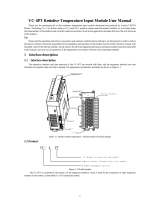
Fluke 712B RTD Calibrators are handheld, battery-operated instruments designed to measure and source a variety of RTDs, with an isolated channel to measure 4-20 mA. They can also simulate RTDs and scale the mA channel to temperature. With step and ramp modes, auto storage of settings, and the ability to set 0% and 100% output parameters, these calibrators are versatile and user-friendly.

Fluke 712B RTD Calibrators are handheld, battery-operated instruments designed to measure and source a variety of RTDs, with an isolated channel to measure 4-20 mA. They can also simulate RTDs and scale the mA channel to temperature. With step and ramp modes, auto storage of settings, and the ability to set 0% and 100% output parameters, these calibrators are versatile and user-friendly.

January 2014
© 2014 Fluke Corporation. All rights reserved. Specifications are subject to change without notice.
All product names are trademarks of their respective companies.
712B
RTD Calibrator
Users Manual
LIMITED WARRANTY AND LIMITATION OF LIABILITY
This Fluke product will be free from defects in material and workmanship for three years from the date of purchase. This
warranty does not cover fuses, disposable batteries, or damage from accident, neglect, misuse, alteration, contamination, or
abnormal conditions of operation or handling. Resellers are not authorized to extend any other warranty on Fluke’s behalf.
To obtain service during the warranty period, contact your nearest Fluke authorized service center to obtain return
authorization information, then send the product to that Service Center with a description of the problem.
THIS WARRANTY IS YOUR ONLY REMEDY. NO OTHER WARRANTIES, SUCH AS FITNESS FOR A PARTICULAR
PURPOSE, ARE EXPRESSED OR IMPLIED. FLUKE IS NOT LIABLE FOR ANY SPECIAL, INDIRECT, INCIDENTAL OR
CONSEQUENTIAL DAMAGES OR LOSSES, ARISING FROM ANY CAUSE OR THEORY. Since some states or countries
do not allow the exclusion or limitation of an implied warranty or of incidental or consequential damages, this limitation of
liability may not apply to you.
Fluke Corporation
P.O. Box 9090
Everett, WA 98206-9090
U.S.A.
Fluke Europe B.V.
P.O. Box 1186
5602 BD Eindhoven
The Netherlands
11/99
i
Table of Contents
Title Page
Introduction .................................................................................................................... 1
How to Contact Fluke ..................................................................................................... 1
Safety Information .......................................................................................................... 3
Safe Working Practices .................................................................................................. 3
Standard Equipment....................................................................................................... 5
Input and Output Terminals ............................................................................................ 7
Keys ............................................................................................................................... 9
Display ........................................................................................................................... 11
Auto Power-Off ............................................................................................................... 13
Auto Backlight-Off .......................................................................................................... 13
Contrast Adjustment ....................................................................................................... 14
Magnet Mounting and Hanging Strap ............................................................................. 15
Measure mA Current ...................................................................................................... 16
Measure Temperature .................................................................................................... 16
Use Resistance-Temperature Detectors (RTDs) ....................................................... 16
Set Temperature Unit ................................................................................................ 16
Source Temperature Signals .......................................................................................... 19
Simulate RTDs ............................................................................................................... 20
Scale mA Channel to Temperature ................................................................................ 22
712B
Users Manual
ii
Set 0 % and 100 % Output Parameters ......................................................................... 22
Step and Ramp Modes .................................................................................................. 23
Select Step or Ramp Mode ....................................................................................... 23
Auto Storage of Settings ........................................................................................... 23
Replace the Batteries .................................................................................................... 24
Maintenance .................................................................................................................. 25
Clean the Product ..................................................................................................... 25
Service Center Calibration or Repair ........................................................................ 25
Replacement Parts ........................................................................................................ 26
Specifications ................................................................................................................ 28
DC mA Measurement ............................................................................................... 28
Ohms Measurement ................................................................................................. 28
Ohms Source ............................................................................................................ 29
RTD Input and Output ............................................................................................... 30
General Specifications .............................................................................................. 32
iii
List of Tables
Table Title Page
1. Summary of Source and Measure Functions ........................................................................ 2
2. International Electrical Symbols ............................................................................................ 4
3. Input/Output Terminals and Connectors ................................................................................ 8
4. Key Functions ........................................................................................................................ 10
5. Elements on the Display ........................................................................................................ 12
6. RTD Types Accepted ............................................................................................................ 17
7. Replacement Parts ................................................................................................................ 26
712B
Users Manual
iv
v
List of Figures
Figure Title Page
1. Standard Equipment .............................................................................................................. 6
2. Input/Output Terminals and Connectors ................................................................................ 7
3. Keys ...................................................................................................................................... 9
4. Elements of a Typical Display ............................................................................................... 11
5. Adjust the Contrast ................................................................................................................ 14
6. Magnet Mounting with Hanging Strap ................................................................................... 15
7. Measure Temperature with an RTD ...................................................................................... 18
8. Source Temperature Signals ................................................................................................. 19
9. Connection for Simulating a 3 and 4 Wire RTD ..................................................................... 21
10. Replace the Batteries ............................................................................................................ 24
11. Replacement Parts ................................................................................................................ 27
712B
Users Manual
vi
1
Introduction
Fluke 712B RTD Calibrator (the Product) is a handheld,
battery-operated instrument that measures and sources a
variety of RTDs. It also has an isolated channel to
measure 4-20 mA. See Table 1.
How to Contact Fluke
To contact Fluke, call one of the following telephone
numbers:
Technical Support USA: 1-800-44-FLUKE (1-800-
443-5853)
Calibration/Repair USA: 1-888-99-FLUKE (1-888-993-
5853)
Canada: 1-800-36-FLUKE (1-800-363-5853)
Europe: +31 402-675-200
Japan: +81-03-6714-3114
Singapore: +65-6799-5566
Mainland China: +86-400-810-3435
Anywhere in the world: +1-425-446-5500
Or, visit Fluke's website at www.fluke.com.
To register your product, visit http://register.fluke.com.
To see, print, or download the latest manual supplement,
visit http://us.fluke.com/usen/support/manuals.
712B
Users Manual
2
Table 1. Summary of Source and Measure Functions
Function Measure Source
Resistance 0 Ω to 4000 Ω 1 Ω to 4000 Ω
RTD
(Resistance-Temperature Detector)
Pt100 Ω (385)
Pt100 Ω (3926)
Pt100 Ω (3916)
Pt200 Ω (385)
Pt500 Ω (385)
Pt1000 Ω (385)
Ni120 Ω (672)
Pt10 (385)
Pt50 (385)
Cu10 (427)
Cu50 (427)
Cu100 (427)
YSI400
Other functions Step, Ramp, Isolated mA channel for 4-20 mA measurement
RTD Calibrator
Safety Information
3
Safety Information
A Warning identifies conditions and procedures that are
dangerous to the user. A Caution identifies conditions
and procedures that can cause damage to the Product or
the equipment under test.
International electrical symbols used on the Product and
in this manual are explained in Table 2.
Safe Working Practices
Review the safety information and comply with all safe
working practices.
Warning
To prevent possible electrical shock, fire, or
personal injury:
Carefully read all instructions.
Read all safety Information before you
use the Product.
Use the Product only as specified, or the
protection supplied by the Product can
be compromised.
Do not use the Product around explosive
gas, vapor, or in damp or wet
environments.
Never apply more than 30 V between any
two terminals, or between any terminal
and earth ground.
Do not connect any test leads to
voltages above 30 V when used with the
product, even if ratings above 30 V
appear on the test leads.
Do not use the Product if it is damaged.
The battery door must be closed and
locked before you operate the Product.
Remove all probes, test leads, and
accessories before the battery door is
opened.
Remove the input signals before you
clean the Product.
Have an approved technician repair the
Product.
Replace the batteries when the low
battery indicator shows to prevent
incorrect measurements.
For safe operation and maintenance of the
Product:
Repair the Product before use if the
battery leaks.
Remove the batteries if the Product is
not used for an extended period of time,
or if stored in temperatures above 50 °C.
If the batteries are not removed, battery
leakage can damage the Product.
712B
Users Manual
4
Table 2. International Electrical Symbols
Earth Ground Battery
Conforms to relevant Australian
Standards.
Risk of danger. Important information. See Manual.
Inspected and licensed by TÜV Product
Services.
Conforms to European Union directives.
CAT II
MEASUREMENT CATEGORY II is
applicable to test and measuring circuits
connected directly to utilization points
(socket outlets and similar points) of the
low voltage MAINS installation.
CAT III
MEASUREMENT CATEGORY III is applicable to test and
measuring circuits connected to the distribution part of the
building’s low-voltage MAINS installation.
CAT IV
MEASUREMENT CATEGORY IV is
applicable to test and measuring circuits
connected at the source of the building’s
low voltage MAINS installation.
Conforms to relevant North American Safety Standards.
This product complies with the WEEE Directive (2002/96/EC) marking requirements. The affixed label indicates that you
must not discard this electrical/electronic product in domestic household waste. Product Category: With reference to the
equipment types in the WEEE Directive Annex I, this product is classed as category 9 "Monitoring and Control
Instrumentation" product. Do not dispose of this product as unsorted municipal waste. Go to Fluke’s website for recycling
information.
RTD Calibrator
Standard Equipment
5
Standard Equipment
The items listed below and shown in Figure 1 are included with your Product. If the Product is damaged or something
is missing, contact the place of purchase immediately. To order replacement parts or spares, see the user-
replaceable parts list in Table 7.
AC175 alligator clips (2 sets)
TL75 test leads (2 sets)
754-8016 alligator clips (1 set)
Stackable test leads (1 set)
4 AA alkaline batteries
Magnet Strap TPAK
712B/714B Safety Sheet
712B Quick Reference Guide
712B Users Manual (available on Fluke’s website)
712B
Users Manual
6
Fluke-75X-Stackable
Test Leads
(1 set)
AC175
Alligator Clips
(2 sets)
TL75
Test Leads
(2 sets)
754-8016,
Alligator Clips
(1 set)
hqu01.eps
Figure 1. Standard Equipment
RTD Calibrator
Input and Output Terminals
7
Input and Output Terminals
Figure 2 shows the input and output terminals on the
Product. Table 3 explains their use.
1
2
3
4
5
6
hqu02.eps
Figure 2. Input/Output Terminals and Connectors
712B
Users Manual
8
Table 3. Input/Output Terminals and Connectors
No. Name Description
,
Measure, mA terminals Input terminals for measuring current.
,
Source/ Measure, RTD, Ω
terminals
Terminals for sourcing or measuring 2W resistance and RTDs.
,
Measure 3W, 4W Terminals for performing 3W and 4W RTD measurements.
RTD Calibrator
Keys
9
Keys
The Product has keys for different purposes. Some keys
have secondary functions that are available when SHIFT
already shows on the display.
Figure 3 shows the Product keys. Table 4 explains their
use.
1
9
10
2
3
4
7
3
5
6
8
hqu03.eps
Figure 3. Keys
712B
Users Manual
10
Table 4. Key Functions
No. Name Description
Turns the power on or off.
Shifts to secondary function when pushed before other keys (Shift mode).
Turns backlight on or off.
Toggles through the 2-, 3-, and 4-wire RTD measurement mode.
Increments output by 25 % of span. Secondary function: toggles between temperature units (°C or
°F.).
Decreases output by 25 % of span.


Up/down arrow increases or decreases the source level. Cycles through different options.
Secondary functions: Enters Ramp or Step mode.
Left/right arrow cycles through and highlights the field to be edited.
In contrast adjustment mode; left- lightens contrast, right- darkens contrast.
Secondary functions: Left arrow enters mA measurement; right arrow enters temperature measurement
.
Enables automatic value span of 100 % or 0 %.
Secondary function: Sets a source value to 100 % or 0 % of span.
Shifts between Measure and Source modes.
Selects RTD (resistance temperature detector) type for measurement and sourcing functions.
Secondary function: Confirms selection.
RTD Calibrator
Display
11
Display
Figure 4 shows the elements of a typical display. Table 5 describes the elements.
9
10
11
12
13
1
2
3
4
5
6
7
8
14
hqu19.eps
Figure 4. Elements of a Typical Display
712B
Users Manual
12
Table 5. Elements on the Display
Item No. Description
100 % of value span
Source or Measure mode
Selected digit that can be edited
Excitation current from the measuring device under test is too low.
Battery usage status
Excitation current from your device under test exceeds the limits of the Product.
Unit of temperature
RTD wire type
Selected RTD type
mA reading
Ω reading
Temperature reading
RTD type list
Display contrast bar
  • Page 1 1
  • Page 2 2
  • Page 3 3
  • Page 4 4
  • Page 5 5
  • Page 6 6
  • Page 7 7
  • Page 8 8
  • Page 9 9
  • Page 10 10
  • Page 11 11
  • Page 12 12
  • Page 13 13
  • Page 14 14
  • Page 15 15
  • Page 16 16
  • Page 17 17
  • Page 18 18
  • Page 19 19
  • Page 20 20
  • Page 21 21
  • Page 22 22
  • Page 23 23
  • Page 24 24
  • Page 25 25
  • Page 26 26
  • Page 27 27
  • Page 28 28
  • Page 29 29
  • Page 30 30
  • Page 31 31
  • Page 32 32
  • Page 33 33
  • Page 34 34
  • Page 35 35
  • Page 36 36
  • Page 37 37
  • Page 38 38
  • Page 39 39
  • Page 40 40

Fluke 712B RTD Calibrators are handheld, battery-operated instruments designed to measure and source a variety of RTDs, with an isolated channel to measure 4-20 mA. They can also simulate RTDs and scale the mA channel to temperature. With step and ramp modes, auto storage of settings, and the ability to set 0% and 100% output parameters, these calibrators are versatile and user-friendly.

Ask a question and I''ll find the answer in the document

Finding information in a document is now easier with AI