Page is loading ...

doepfer
System A - 100 Wasp Filter (
VCF 5)
A-124
1
1. Introduction
Module A-124 (WASP FILTER) is a special voltage-
controlled multimode filter with a cut-off slope of
-12dB / octave.
The
special feature
of the A-124 is the peculiar
electronic circuitry of the Wasp synthesizer manufac-
tured at the end of the seventies by the UK company
EDP (Electronic Dream Plant). This synthesizer is well
known for its eye-catching black/yellow wasp design
and its distinctive filter. Its circuitry "abuses" digital
inverters as analog operational amplifiers leading to
distortions and other "dirty" effects that generate the
specific sound of this filter.
Our version is equipped with a band pass output and
a combined low/notch/high pass output. For this
latter output a control knob defines the
relative
amounts of low and high pass signals. If both si-
gnals appear at the same level (i.e. middle position of
the Mix knob) one obtains a notch filter. Otherwise the
low or high pass signal predominates.
Resonance
can be adjusted manually. The filter can't
go into self oscillation, in contrast to most of the other
VCFs in the A-100 system.
The cut-off frequency can be adjusted manually, or
by voltage control. Two CV inputs are available.
Audio
In
CV 2
CV 2
BP Out
LP/HP Out
Res.
CV 1
A-124
WASP FILTER
Frq.
Level
Mix

A-124
Wasp Filter (VCF 5)
System A - 100
doepfer
2
2. VCF 5 - Overview
Controls:
1
Audio Level
: Input signal attenuator
2
Frq.
: Cut-off frequency control
3
CV 2 : Attenuator for filter CV
§
4 Res. : Resonance control
5
Mix
: Control for relative amounts of low
and high pass signal
In / Outputs:
!
Audio In
: Audio input to the filter
"
CV 1 : Cut-off frequency CV input
§ CV 2 : ditto, level controlled by 3
$
BP Out
: Band-pass filter output
%
LP/HP Out : Mixed low-pass / high-pass filter out-
put
A-124
VCF 5
CV 1
CV 2
Audio In
Frq.
CV 2
Res.
Mix
Lev.
➀
➁
➂
➃
➄
WASP FILTER
0
10
0
10
0
10
0
10
LP
HP
LP/HP Out
BP Out

doepfer
System A - 100 Wasp Filter (
VCF 5)
A-124
3
3. Basics
Module A-124 contains three filter types: low-pass,
high-pass and band-pass. Low-pass and high-pass
signals are internally mixed and appear as the mixed
LP/HP output %. The mix control 5 governs the
relative amounts of low-pass and high-pass.
With the mix control fully counterclockwise, at "LP",
the mix output forms a pure low-pass. This is the
most common type of filter in analogue sound produc-
tion, which filters out the higher parts of the sound
spectrum, and lets the lower frequencies pass un-
changed. Cut-off frequency f
C
determines the fre-
quency at which this occurs (see Fig. 1).
With the mix control fully clockwise, at ”HP”, the mix
output is a pure high-pass. The high-pass filter is a
mirror-image of the low-pass filter: while it lets fre-
quencies that are higher than the cut-off frequency f
C
through, it attenuates frequencies below the cut-off
point (see Fig. 1).
With the mix control in its middle position, the result is
a symmetrical notch filter, letting through the upper
and lower end of the frequency spectrum, but rejec-
ting a band in the middle. If the mid-frequency
is
modulated by an LFO, the result sounds very similar
to phasing.
Fig. 1: Typical response curves of the four filter types.
When the mix control deviates from the middle posi-
tion the
notch
is asymmetrical, i.e. the low-pass or
high-pass share predominates.
In the band-pass filter, which has its own output, both
ends of the frequency spectrum are attenuated (see
Fig. 1), and the cut-off frequency f
C
becomes the mid
frequency.
It gives you the ability to highlight a
particular frequency band.
f
c
Out
Freq.
Out
Freq.
Low Pass
High Pass
f
c
f
c
Freq.Freq.
Out
Out
f
c
Band PassNotch

A-124
Wasp Filter (VCF 5)
System A - 100
doepfer
4
4. Controls
1 Lev.
This attenuator controls the
input level
of the signal to
be filtered, entering the module at input ! .
H
If the filter’s output signal is distorted, turn
this control down, unless the distortion is
wanted as a special effect.
2 Freq.
The filter frequency is adjusted with this control.
3 CV 2
If you want to control or modulate the cut-off frequency
by a voltage patched into input
§
,
use attenuator
3
CV 2
to set
the level of voltage control
.
4 Res.
With this control you adjust the resonance of the filter
(also known as emphasis or Q), which emphasises
the frequencies around the cut-off frequency f
C
. As the
value for Q gets higher, the frequencies around the
cut-off frequency f
C
are emphasised. Fig. 2 shows this
process using a low-pass filter as an example (a
high-pass filter would produce a mirror-image). This
way, you can make the frequencies around the cut-off
point stand out more.
In band-pass mode, an increase in Q’s value makes
the bandwidth narrower. The same is true of notch
mode, but of course in this case this narrower band will
be rejected, instead of let through.
Fig. 2:
How resonance affects the response of a
low-pass filter around the cut-off frequency.
f
c
Resonance
Q
Frequency
➨
➨➨
➨
0 db

doepfer
System A - 100 Wasp Filter (
VCF 5)
A-124
5
5 Mix
Mix control 5 adjusts the relative amounts of low-pass
and high-pass signals appearing at the LP/HP mix
output
%
.
You can move from pure low pass (LP position on the
control) via asymmetrical / symmetrical / asymmetrical
notch to pure high pass (position HP).
5. In / Outputs
! Audio In
This socket is the filter’s
audio input
. Patch the
output of a sound source (such as a VCO, noise
generator or mixer) into it.
"
CV 1
Socket CV 1 is a voltage control input for the filter
frequency. It works approximately to the 1 V / octave
standard (like a VCO). Due to the simple Wasp filter
design the control scale is not very precise.
If you patch a modulation source (eg LFO, ADSR) into
this input, the cut-off frequency of the filter will be
modulated by its voltage: ie, the sound color changes
according to the voltage put out by the modulator.
§ CV 2
Socket CV 2 is another voltage control input for the
filter. Unlike CV 1, you can control the level of voltage
- the intensity of the modulation effect on the filter -
with attenuator
3
.
$ BP Out
This is the band-pass output.

A-124
Wasp Filter (VCF 5)
System A - 100
doepfer
6
% LP/HP Out
This is the mixed low-pass/high-pass output.
6. User examples
The A-124’s cut-off frequency can be modulated in a
variety of ways (see table below).
Modulator Result
LFO
cyclical changes of the sound spectrum
(e.g. A-145, A-146, A-147, A-191)
ADSR
gradual change of the sound spectrum
(e.g. A-140, A-141, A-142)
random
random sound changes (e.g. A-118, A-148)
pitch CV
pitch-related filter opening and closing
sequencer
rhythmical sound changes (e.g. A-155)
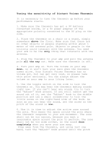
theremin
body controlled sound changes (e.g. A-178)
light CV
sound changes controlled by illumination inten-
sity (e.g. A-179)
env. follower
sound changes controlled by the envelope of
an audio signal (e.g. A-119)
foot control
sound changes controlled by foot controllers
(e.g. A-177)
MIDI
sound changes controlled by MIDI events e.g.
MIDI controllers (A-191)
...

doepfer
System A - 100 Wasp Filter (
VCF 5)
A-124
7
7. Patch-Sheet
The following diagrams of the module can help you
recall your own Patches. They’re designed so that
a complete 19” rack of modules will fit onto an A4
sheet of paper.
Photocopy this page, and cut out the pictures of
this and your other modules. You can then stick
them onto another piece of paper, and create a
diagram of your own system.
Make multiple copies of your composite diagram,
and use them for remembering good patches and
set-ups.
P • Draw in patchleads with colored pens.
• Draw or write control settings in the
little white circles.
A-124
VCF 5
CV 1
CV 2
Audio In
Frq.
CV 2
Res.
Mix
Lev.
WASP FILTER
0
10
0
10
0
10
0
10
LP
HP
LP/HP Out
BP Out
A-124
VCF 5
CV 1
CV 2
Audio In
Frq.
CV 2
Res.
Mix
Lev.
WASP FILTER
0
10
0
10
0
10
0
10
LP
HP
LP/HP Out
BP Out
A-124
VCF 5
CV 1
CV 2
Audio In
Frq.
CV 2
Res.
Mix
Lev.
WASP FILTER
0
10
0
10
0
10
0
10
LP
HP
LP/HP Out
BP Out

A-124
Wasp Filter (VCF 5)
System A - 100
doepfer
8
/