2
Important Safety Instructions
To the CATV system installer: This reminder is provided
to call the CATV system installer’s attention to Article 820-
44 of the NEC that provides guidelines for proper grounding and, in
particular, species that the cable ground shall be connected to the
grounding system of the building, as close to the point of cable entry
as practical.
SAFETY POINTS YOU SHOULD KNOW ABOUT YOUR HITACHI LCD TELEVISION
Our reputation has been built on the quality, performance, and ease of service of Hitachi LCD televisions.
Safety is also foremost in our minds in the design of these units. To help you operate these products properly, this section illustrates safety
tips which will be of benet to you. Please read it carefully and apply the knowledge you obtain from it to the proper operation of your Hitachi
LCD television.
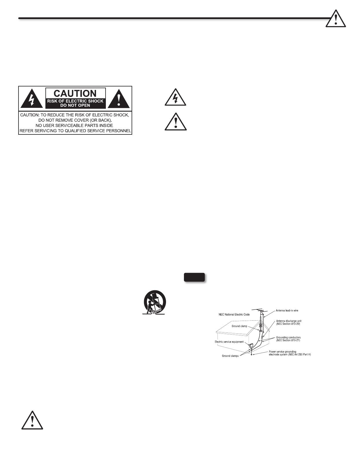
The lightning ash with arrowhead symbol, within an equilateral
triangle, is intended to alert the user to the presence of uninsulated
“dangerous voltage” within the product’s enclosure that may be of a
sufcient magnitude to constitute a risk of electric shock to a person.
The exclamation point within an equilateral triangle, is intended to
alert the user to the presence of important operating and maintenance
(servicing) instructions in the literature accompanying the appliance.
NOTE
READ BEFORE OPERATING EQUIPMENT
Follow all warnings and instructions marked on this LCD
television.
Read these instructions.1.
Keep these instructions.2.
Heed all warnings.3.
Follow all instructions.4.
Do not use this apparatus near water.5.
Clean only with a dry cloth.6.
Do not block any ventilation openings. Install in accordance 7.
with the manufacturer’s instructions.
Do not install near any heat sources such as radiators, heat 8.
registers, stoves, or other apparatus (including ampliers) that
produce heat.
Do not defeat the safety purpose of the polarized or grounding-9.
type plug. A polarized plug has two blades with one wider
than the other. A grounding type plug has two blades and
a third grounding prong. The wide blade or the third prong
are provided for your safety. If the provided plug does not t
into your outlet, consult an electrician for replacement of the
obsolete outlet.
Protect the power cord from being walked on or pinched 10.
particularly at plugs, convenience receptacles, and the point
where they exit from the apparatus.
Only use the attachments/accessories specied by the 11.
manufacturer.
Use only with the cart, stand, tripod, bracket, or 12.
table specied by the manufacturer, or sold with
the apparatus. When a cart is used, use caution
when moving the cart/apparatus combination to
avoid injury from tip-over.
Unplug this apparatus during lightning storms or when unused 13.
for long periods of time.
Refer all servicing to qualied service personnel. Servicing 14.
is required when the apparatus has been damaged in any
way, such as power-supply cord or plug is damaged, liquid
has been spilled or objects have fallen into the apparatus, the
apparatus has been exposed to rain or moisture, does not
operate normally, or has been dropped.
Televisions are designed to comply with the recommended 15.
safety standards for tilt and stability. Do not apply excessive
pulling force to the front, or top, of the cabinet which could
cause the product to overturn resulting in product damage
and/or personal injury.
Follow instructions for wall, shelf or ceiling mounting as 16.
recommended by the manufacturer.
An outdoor antenna should not be located in the vicinity of 17.
overhead power lines or other electrical circuits.
If an outside antenna is connected to the receiver be sure the 18.
antenna system is grounded so as to provide some protection
against voltage surges and built up static charges. Section
810 of the National Electric Code, ANSI/NFPA No. 70-1984,
provides information with respect to proper grounding for the
mast and supporting structure, grounding of the lead-in wire
to an antenna discharge unit, size of grounding connectors,
location of antenna discharge unit, connection to grounding
electrodes and requirements for the grounding electrode.
Power source
This LCD television is designed to operate on 120 volts 60 Hz, AC current. Insert the power cord into a 120 volt 60 Hz outlet. The mains plug
is used as the disconnect device and shall remain readily operable.
To prevent electric shock, do not use the LCD television’s (polarized) plug with an extension cord, receptacle, or other outlet unless the
blades and ground terminal can be fully inserted to prevent blade exposure.
Never connect the LCD television to 50 Hz, direct current, or anything other than the specied voltage.
This television’s factory default settings as shipped meet Energy Star requirements.
Please see the ENERGY OPTIONS section of this operating guide for more energy saving tips.
Caution
Never remove the back cover of the LCD television as this can expose you to very high voltages and other hazards. If the
television does not operate properly, unplug the LCD television and call your authorized dealer or service center.
Adjust only those controls that are covered in the instructions, as improper changes or modications not expressly approved by
Hitachi could void the user’s warranty.


