NordicTrack NETL18711.2 User manual
- Category
- Treadmills
- Type
- User manual
This manual is also suitable for

CAUTION
Read all precautions and instruc-
tions in this manual before using
this equipment. Save this manual
for future reference.
QUESTIONS?
If you have questions, or if there are
missing parts, please contact us:
UNITED KINGDOM
Call: 08457 089 009
From Ireland: 053 92 36102
Website: www.iconsupport.eu
E-mail: [email protected]
Write:
ICON Health & Fitness, Ltd.
c/o HI Group PLC
Express Way
CASTLEFORD
WF10 5QJ
UNITED KINGDOM
AUSTRALIA
Call: 1800 993 770
E-mail: [email protected]
Write:
ICON Health & Fitness
PO Box 635
WINSTON HILLS NSW 2153
AUSTRALIA
Model No. NETL18711.0
Serial No.
Write the serial number in the space
above for reference.
Serial Number
Decal
USER’S MANUAL
www.iconeurope.com

2
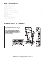
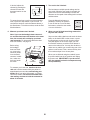
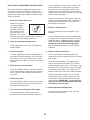
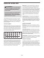
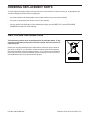
This drawing shows the locations of the warn-
ing decals. If a decal is missing or illegible,
call the telephone number on the front
cover of this manual and request a free
replacement decal. Apply the decal in the
location shown. Note: The decals may not
be shown at actual size.
WARNING DECAL PLACEMENT
256836
NORDICTRACK is a registered trademark of ICON IP, Inc.
WARNING DECAL PLACEMENT . . . . . . . . . . . . . . . . . . . . . . . . . . . . . . . . . . . . . . . . . . . . . . . . . . . . . . . . . . . . . . .2
IMPORTANT PRECAUTIONS ..................................................................3
BEFORE YOU BEGIN. . . . . . . . . . . . . . . . . . . . . . . . . . . . . . . . . . . . . . . . . . . . . . . . . . . . . . . . . . . . . . . . . . . . . . . .5
PART IDENTIFICATION CHART. . . . . . . . . . . . . . . . . . . . . . . . . . . . . . . . . . . . . . . . . . . . . . . . . . . . . . . . . . . . . . . .6
ASSEMBLY . . . . . . . . . . . . . . . . . . . . . . . . . . . . . . . . . . . . . . . . . . . . . . . . . . . . . . . . . . . . . . . . . . . . . . . . . . . . . . . .7
THE CHEST HEART RATE MONITOR. . . . . . . . . . . . . . . . . . . . . . . . . . . . . . . . . . . . . . . . . . . . . . . . . . . . . . . . . .15
OPERATION AND ADJUSTMENT .............................................................16
HOW TO FOLD AND MOVE THE TREADMILL . . . . . . . . . . . . . . . . . . . . . . . . . . . . . . . . . . . . . . . . . . . . . . . . . . .29
TROUBLESHOOTING ......................................................................30
EXERCISE GUIDELINES ....................................................................33
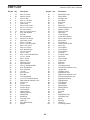
PART LIST. . . . . . . . . . . . . . . . . . . . . . . . . . . . . . . . . . . . . . . . . . . . . . . . . . . . . . . . . . . . . . . . . . . . . . . . . . . . . . . .34
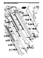
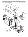
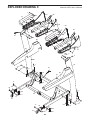
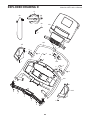
EXPLODED DRAWING. . . . . . . . . . . . . . . . . . . . . . . . . . . . . . . . . . . . . . . . . . . . . . . . . . . . . . . . . . . . . . . . . . . . . .36
ORDERING REPLACEMENT PARTS. . . . . . . . . . . . . . . . . . . . . . . . . . . . . . . . . . . . . . . . . . . . . . . . . . . Back Cover
RECYCLING INFORMATION ......................................................... Back Cover
TABLE OF CONTENTS

3
1. Before beginning any exercise program,
consult your physician. This is especially
important for persons over age 35 or persons
with pre-existing health problems.
2. It is the responsibility of the owner to ensure
that all users of this treadmill are adequately
informed of all warnings and precautions.
3. Use the treadmill only as described.
4. Keep the treadmill indoors, away from mois-
ture and dust. Do not put the treadmill in a
garage or covered patio, or near water.
5. Place the treadmill on a level surface, with
at least 8 ft. (2.4 m) of clearance behind it
and 2 ft. (0.6 m) on each side. Do not place
the treadmill on any surface that blocks air
openings. To protect the floor or carpet from
damage, place a mat under the treadmill.
6. Do not operate the treadmill where aerosol
products are used or where oxygen is being
administered.
7. Keep children under age 12 and pets away
from the treadmill at all times.
8. The treadmill should be used only by per-
sons weighing 350 lbs. (159 kg) or less.
9. Never allow more than one person on the
treadmill at a time.
10. Wear appropriate exercise clothes while
using the treadmill. Do not wear loose
clothes that could become caught in the
treadmill. Athletic support clothes are recom-
mended for both men and women. Always
wear athletic shoes. Never use the treadmill
with bare feet, wearing only stockings, or in
sandals.
11. When connecting the power cord (see page
16), plug the power cord into an earthed
circuit. No other appliance should be on the
same circuit. When replacing the fuse in the
power cord adapter, insert an ASTA-approved
BS1362, 13-amp fuse into the fuse carrier.
12. If an extension cord is needed, use only a
3-conductor, 14-gauge (1 mm
2
) cord that is
no longer than 5 ft. (1.5 m).
13. Keep the power cord away from heated
surfaces.
14. Never move the walking belt while the power
is turned off. Do not operate the treadmill
if the power cord or plug is damaged, or if
the treadmill is not working properly. (See
TROUBLESHOOTING on page 30 if the tread-
mill is not working properly.)
15. Read, understand, and test the emergency
stop procedure before using the treadmill
(see HOW TO TURN ON THE POWER on
page 18).
16. Never start the treadmill while you are stand-
ing on the walking belt. Always hold the
handrails while using the treadmill.
17. The treadmill is capable of high speeds.
Adjust the speed in small increments to
avoid sudden jumps in speed.
18. The heart rate monitor is not a medical
device. Various factors, including the user’s
movement, may affect the accuracy of heart
rate readings. The heart rate monitor is
intended only as an exercise aid in determin-
ing heart rate trends in general.
19. Never leave the treadmill unattended while
it is running. Always remove the key, press
the power switch into the off position (see
the drawing on page 5 for the location of the
power switch), and unplug the power cord
when the treadmill is not in use.
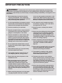
WARNING: To reduce the risk of serious injury, read all important precautions and
instructions in this manual and all warnings on your treadmill before using your treadmill. ICON
assumes no responsibility for personal injury or property damage sustained by or through the use of
this product.
IMPORTANT PRECAUTIONS

4
20. Do not attempt to move the treadmill until it
is properly assembled. (See ASSEMBLY on
page 7, and HOW TO FOLD AND MOVE THE
TREADMILL on page 29.) You must be able
to safely lift 45 lbs. (20 kg) to raise, lower, or
move the treadmill.
21. When folding or moving the treadmill, make
sure that the storage latch is holding the
frame securely in the storage position.
22. Never insert any object into any opening on
the treadmill.
23. Inspect and properly tighten all parts of the
treadmill regularly.
24. DANGER: Always unplug the power
cord immediately after use, before cleaning
the treadmill, and before performing the
maintenance and adjustment procedures
described in this manual. Never remove the
motor hood unless instructed to do so by an
authorized service representative. Servicing
other than the procedures in this manual
should be performed by an authorized ser-
vice representative only.
25. The treadmill is intended for home use only.
Do not use the treadmill in any commercial,
rental, or institutional setting.
26. Over exercising may result in serious injury
or death. If you feel faint or if you experience
pain while exercising, stop immediately and
cool down.
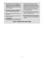
SAVE THESE INSTRUCTIONS

5
Thank you for selecting the revolutionary
NORDICTRACK
®
T23.0 treadmill. The T23.0 treadmill
offers an impressive selection of features designed
to make your workouts at home more enjoyable and
effective. And when you’re not exercising, the unique
treadmill can be folded up, requiring less than half the
oor space of other treadmills.
For your benet, read this manual carefully before
using the treadmill. If you have questions after
reading this manual, please see the front cover of this
manual. To help us assist you, please note the product
model number and serial number before contacting us.
The model number and the location of the serial num-
ber decal are shown on the front cover of this manual.
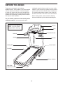
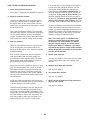
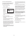
Before reading further, please review the drawing
below and familiarize yourself with the labeled parts.
BEFORE YOU BEGIN
Handrail
Upright
Tray
Key/Clip
Power Switch
Walking Belt
Platform Cushion
Foot Rail
Idler Roller
Adjustment Screws
Console
Heart Rate Monitor
Length: 6 ft. 8 in. (203 cm)
Width: 3 ft. 2 in. (97 cm)
Weight: 238 lbs. (108 kg)

6
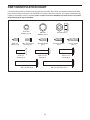
1/4" x 1/2"
Bolt (36)–4
1/4" Star
Washer (35)–8
#8 x 3/4" Screw
(2)–6
3/8" Star
Washer (13)–4
3/8" Nut (12)–2
5/16" Star
Washer (11)–8
#10 x 3/4" Screw
(9)–4
3/8" x 2 3/4" Screw (7)–4
3/8" x 1 3/4" Bolt (6)–1
3/8" x 2" Bolt (3)–2
#8 x 1/2" Ground
Screw (10)–1
#8 x 1/2"
Screw (1)–6
5/16" x 1 1/2"
Bolt (4)–6
3/8" x 1 1/4"
Screw (8)–4
#8 x 1" Screw
(25)–4
5/16" x 1"
Screw (5)–4
PART IDENTIFICATION CHART
Use the drawings below to identify small parts used for assembly. The number in parentheses below each draw-
ing is the key number of the part, from the PART LIST near the end of this manual. The number following the key
number is the quantity used for assembly. Note: If a part is not in the hardware kit, check to see if it is preat-
tached. Extra parts may be included.

7
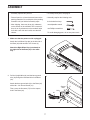
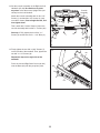
1. Make sure that the power cord is unplugged.
Attach the Left Wheel Cap (96) to the left side of
the Base (94) with two #8 x 3/4" Screws (2).
Attach the Right Wheel Cap (not shown) to
the right side of the Base (94) in the same
way.
1
96
94
2
2. Pull the Upright Wire (81) and the base ground
wire (A) through the indicated hole in the Base
(94).
Attach the base ground wire (A) to the Base (94)
with a #8 x 1/2" Ground Screw (10).
Then, press the Grommet (77) into the square
hole in the Base (94).
81
2
94
Hole
10
A
Square
Hole
77
ASSEMBLY
• Assembly requires two persons.
• Place all parts in a cleared area and remove the
packing materials. Do not dispose of the packing
materials until you nish all assembly steps.
• After shipping, there may be an oily substance
on the exterior of the treadmill. This is normal. If
there is an oily substance on the treadmill, wipe
it off with a soft cloth and a mild, non-abrasive
cleaner.
• To identify small parts, see page 6.
• Assembly requires the following tools:
the included hex keys
one adjustable wrench
one Phillips screwdriver
To avoid damaging parts, do not use power tools.

8
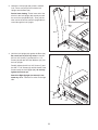
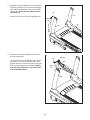
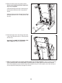
3. Identify the Left Upright (89), which is marked
“Left.” Have a second person hold the Left
Upright near the Base (94).
See the inset drawing. Tie the lower end of the
wire tie in the Left Upright (89) securely around
the end of the Upright Wire (81). Then, pull the
other end of the wire tie until the Upright Wire is
routed through the Left Upright.
81
3
81
89
Wire
Tie
Wire
Tie
89
94
81
4. Hold the Left Upright (89) against the Base (94).
Be careful not to pinch any wires. Insert two
3/8" x 2 3/4" Screws (7) and two 3/8" x 1 1/4"
Screws (8) with two 3/8" Star Washers (13) into
the Left Upright.
Partially tighten the 3/8" x 2 3/4" Screws (7) and
the 3/8" x 1 1/4" Screws (8) until the heads of the
Screws touch the Left Upright (89); do not fully
tighten the Screws yet.
Attach the Right Upright (not shown) in the
same way. Note: There are no wires on the right
side.
89
94
4
8
7
13
13

9
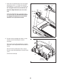
5. Identify the Left and Right Base Covers (82, 83).
Slide the Left Base Cover onto the Left Upright
(89). Slide the Right Base Cover onto the Right
Upright (90). Do not press the Base Covers
into place yet.
Remove the wire tie from the Upright Wire (81).
89
82
90
83
5
Wire
Tie
81
6. Identify the Left Handrail (88), and hold it near
the Left Upright (89).
Tie the wire tie in the Left Handrail (88) securely
around the end of the Upright Wire (81). Then,
pull the other end of the wire tie until the Upright
Wire is routed through the Left Handrail. Make
sure that the Upright Wire is on the left side
of the indicated bracket.
88
6
89
81
Wire
Tie
Bracket

10
7. Attach the Left Handrail (88) to the Left Upright
(89) with two 5/16" x 1" Screws (5), two 5/16"
Star Washers (11), and a 5/16" x 1 1/2" Bolt (4).
Do not tighten the Screws and the Bolt yet.
Attach the Right Handrail (87) in the same
way.
Slide the Upright Wire (81) to the right side of
the indicated bracket. Be careful not to pinch
the Upright Wire between the Left Outside
Handrail Cover (80) and the bracket.
89
7
88
87
4
4
5
5
11
80
11
81
Bracket
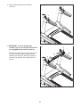
8. Set the console assembly face down on a soft
surface to avoid scratching the console
assembly.
Remove the screws (B) attaching the Crossbar
(93). Note: There may be fewer screws than are
shown.
Next, lift off the Crossbar (93). Then, remove
the two screws (B) attaching the Console Frame
(104).
Discard the screws (B).
93
Console
Assembly
B
8
B
B
104

11
9. Remove and discard the four indicated
screws (C).
C
9
C
10. IMPORTANT: To avoid damaging the
Crossbar (93), do not use power tools and do
not overtighten the #10 x 3/4" Screws (9).
Orient the Crossbar (93) as shown. Tighten four
#10 x 3/4" Screws (9) about halfway into the
Handrails (87, 88). Next, slide the Crossbar as
far forward as possible. Then, tighten the four
Screws.
93
88
9
10
9
87

12
12. With the help of a second person, hold the con-
sole assembly near the Left Handrail (88).
Connect the Upright Wire (81) to the console
wire. See the inset drawing. The connectors
should slide together easily and snap into
place. If they do not, turn one connector and try
again. IF YOU DO NOT CONNECT THE CON-
NECTORS PROPERLY, THE CONSOLE MAY
BECOME DAMAGED WHEN YOU TURN ON
THE POWER. Then, remove the wire tie from
the Upright Wire.
Connect the ground wire from the console
assembly to the Console Ground Wire (105),
and insert the wires into the hole in the console
assembly.
Console
Assembly
Wire
Tie
88
81
81
Console
Wire
12
Ground
Wire
105
11. Attach the Console Frame (104) to the Handrails
(87, 88) with four 5/16" x 1 1/2" Bolts (4) and four
5/16" Star Washers (11).
11
104
87
88
4
11
4
11
Console
Wire

13
14. Firmly tighten the two 3/8" x 2 3/4" Screws (7)
on the left side of the treadmill. Then, tighten the
two 3/8" x 1 1/4" Screws (8).
Repeat this step on the right side of the
treadmill.
Press the Left and Right Base Covers (82, 83)
onto the Base (94) until they snap into place.
14
83
8
82
94
7
13. Set the console assembly on the Right and Left
Handrails (87, 88). Be careful not to pinch
any wires. Insert the excess Upright Wire (not
shown) into the Left Handrail.
Attach the console assembly with six #8 x 1/2"
Screws (1) and two #8 x 3/4" Screws (2) (only
one side is shown). Start all eight Screws, and
then tighten them.
Then, attach two Console Clamps (106) to the
console assembly with four #8 x 1" Screws (25).
See step 7. Fully tighten the four 5/16" x 1"
Screws (5) and the two 5/16" x 1 1/2" Bolts (4).
88
1
13
Console
Assembly
1
87
2
25
1
1
25
106
106

14
17. Make sure that all parts are properly tightened before you use the treadmill. If there are sheets of plastic
on the treadmill decals, remove the plastic. To protect the oor or carpet, place a mat under the treadmill.
Note: Extra hardware may be included. Keep the included hex keys in a secure place; one of the hex keys is
used to adjust the walking belt (see pages 31 and 32).
16. Attach the upper end of the Storage Latch (53)
to the Frame (56) with a 3/8" x 2" Bolt (3) and a
3/8" Nut (12).
See HOW TO LOWER THE TREADMILL FOR
USE on page 29. Lower the Frame (56).
16
53
12
56
3
15. Raise the Frame (56) to the position shown.
Have a second person hold the Frame until
step 16 is completed.
Orient the Storage Latch (53) so that the large
barrel and the latch knob are in the positions
shown.
Attach the lower end of the Storage Latch (53) to
the Base (94) with a 3/8" x 2" Bolt (3) and a 3/8"
Nut (12).
15
53
Large
Barrel
56
Latch
Knob
12
3
94

15
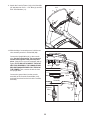
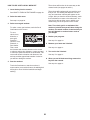
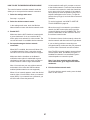
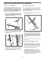
HOW TO PUT ON THE HEART RATE MONITOR
The heart rate
monitor consists of
a chest strap and a
sensor. Insert the
tab on one end of
the chest strap into
the hole in one end
of the sensor as
shown. Then, press
the end of the sen-
sor under the buckle
on the chest strap.
The tab should be
flush with the front of
the sensor.
The heart rate moni-
tor must be worn
under your clothes,
tight against your
skin. Wrap the heart
rate monitor around
your chest in the
location shown.
Make sure that
the logo is right-
side-up. Then, attach the other end of the chest strap
to the sensor. Adjust the length of the chest strap, if
necessary.
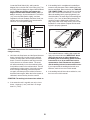
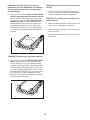
Pull the sensor away from your body a few inches and
locate the two electrode areas, which are covered by
shallow ridges. Using saline solution such as saliva or
contact lens solution, wet the electrode areas. Then,
return the sensor to a position against your chest.
CARE AND MAINTENANCE
• Thoroughly dry the sensor with a soft towel after
each use. Moisture may keep the sensor activated,
shortening the life of the battery.
• Store the heart rate monitor in a warm, dry place.
Do not store the heart rate monitor in a plastic bag
or other container that may trap moisture.
• Do not expose the heart rate monitor to direct sun-
light for extended periods of time; do not expose it
to temperatures above 122° F (50° C) or below 14°
F (-10° C).
• Do not excessively bend or stretch the sensor
when using or storing the heart rate monitor.
• To clean the sensor, use a damp cloth and a small
amount of mild soap. Then, wipe the sensor with a
damp cloth and thoroughly dry it with a soft towel.
Never use alcohol, abrasives, or chemicals to clean
the sensor. Hand wash and air dry the chest strap.
TROUBLESHOOTING
If the heart rate monitor does not function properly, try
the steps below.
• Make sure that you are wearing the heart rate mon-
itor as described at the left. If the heart rate monitor
does not function when positioned as described,
move it slightly lower or higher on your chest.
• If heart rate readings are not displayed until you
begin perspiring, rewet the electrode areas.
• For the console to display heart rate readings, you
must be within arm’s length of the console.
• If there is a battery cover on the back of the sensor,
replace the battery with a new battery of the same
type.
• The heart rate monitor is designed to work with
people who have normal heart rhythms. Heart rate
reading problems may be caused by medical con-
ditions such as premature ventricular contractions
(pvcs), tachycardia bursts, and arrhythmia.
• The operation of the heart rate monitor can be
affected by magnetic interference from high power
lines or other sources. If you suspect that magnetic
interference is causing a problem, try relocating the
fitness equipment.
THE CHEST HEART RATE MONITOR
Sensor
Buckle
Tab
Chest
Strap
Tabs
Sensor

16
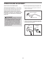
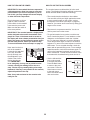
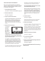
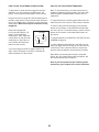
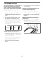
HOW TO PLUG IN THE POWER CORD
This product must be earthed. If it should malfunc-
tion or break down, earthing provides a path of least
resistance for electric current to reduce the risk of
electric shock. This product’s power cord has an
equipment-earthing conductor and an earthing plug.
IMPORTANT: If the power cord is damaged, it must
be replaced with a manufacturer-recommended
power cord.
Follow the steps below to plug in the power cord.
1. Plug the indicated end of the power cord into the
socket on the treadmill.
2. Plug the power cord into an appropriate outlet that
is properly installed and earthed in accordance with
all local codes and ordinances.
DANGER: Improper connection of
the equipment-earthing conductor can result
in an increased risk of electric shock. Check
with a qualified electrician or serviceman if
you are in doubt as to whether the product
is properly earthed. Do not modify the plug
provided with the product—if it will not fit
the outlet, have a proper outlet installed by a
qualified electrician.
OPERATION AND ADJUSTMENT
IT
FR/SP
UK
GR
RU
HU
Socket on Treadmill
IT
FR/SP
UK
GR
RU
HU
UK
GR
FR/SP
IT
AUS
AUS
Outlet
UK
Australia
Outlet
Power Cord

17
ETNE18711
(NETL18711)
CONSOLE
DIAGRAM
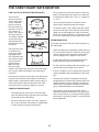
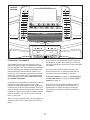
FEATURES OF THE CONSOLE
The treadmill console offers an impressive array of
features designed to make your workouts more effec-
tive and enjoyable. The console features revolutionary
iFit Live technology that enables the treadmill to com-
municate with your wireless network. With iFit Live
technology, you can download personalized workouts,
create your own workouts, track your workout results,
and access many other features. See www.iFit.com
for complete information.
In addition, the console features a selection of onboard
workouts, including eight calorie workouts, eight
intensity workouts, eight speed workouts, eight incline
workouts, and six iFit Live demo workouts. Each work-
out automatically controls the speed and incline of the
treadmill as it guides you through an effective exercise
session. In addition, you can set a calorie, time, dis-
tance, or pace goal.
When you use the manual mode, you can change the
speed and incline of the treadmill with the touch of a
button.
As you exercise, the console will display instant exer-
cise feedback. You can also measure your heart rate
using the handgrip heart rate monitor or the chest heart
rate monitor.
You can even browse the Internet or listen to your
favorite workout music or audio books with the con-
sole’s stereo sound system while you exercise.
To turn on the power, see page 18. To learn how to
use the touch screen, see page 18. To set up the
console, see page 19.
Note: The console can display speed and distance
in either miles or kilometers. To nd which unit of
measurement is selected, see step 4 on page 25.
For simplicity, all instructions in this section refer to
kilometers.

18
HOW TO TURN ON THE POWER
IMPORTANT: If the treadmill has been exposed to
cold temperatures, allow it to warm to room tem-
perature before you turn on the power. If you do
not do this, you may damage the console display
or other electrical components.
Plug in the power cord (see
page 16). Next, locate the
power switch on the treadmill
frame near the power cord.
Make sure that the switch is
in the reset position.
IMPORTANT: The console features a display demo
mode, designed to be used if the treadmill is dis-
played in a store. If the demo mode is turned on,
the display will show a demo presentation after you
plug in the power cord and press the power switch
into the reset position, before you insert the key.
To turn off the demo mode, see step 6 on page 25.
Next, stand on the foot
rails of the treadmill.
Locate the clip attached
to the key, and slide
the clip securely onto
the waistband of your
clothes. Then, insert
the key into the con-
sole. IMPORTANT:
In an emergency, the key can be pulled from the
console, causing the walking belt to slow to a
stop. Test the clip by carefully taking a few steps
backward; if the key is not pulled from the console,
adjust the position of the clip.
Note: It may take a minute for the console to be
ready for use.
HOW TO USE THE TOUCH SCREEN
The console features a tablet with a full-color touch
screen. The following information will help you become
familiar with the tablet’s advanced technology:
• The console functions similarly to other tablets.
You can slide or ick your nger against the screen
to move certain images on the screen, such as
the displays in a workout (see step 5 on page 20).
However, you cannot zoom in and out by sliding your
ngers on the screen.
• The screen is not pressure sensitive. You do not
need to press hard on the screen.
• To type information into a text box, touch the text
box to view the keyboard. To use numbers or other
characters on the keyboard, touch the ?123 but-
ton. To view more characters, touch the Alt button.
Touch the Alt button again to return to the number
keyboard. To return to the letter keyboard, touch the
ABC button. To use a capital character, touch the
button with an upward-facing arrow. To use multiple
capital characters, touch the arrow button again. To
return to the lowercase keyboard, touch the arrow
button a third time. To clear the last character, touch
the button with a backward-facing arrow and an X.
• Use the indicated but-
tons on the console
to navigate the tablet.
Press the Back button
to return to the previ-
ous screen. Press the
Home button to return
to the main menu.
Note: The center button
does not function.
Reset
ETNE18711
(NETL18711)
Key
Clip
Back
Home

19
HOW TO SET UP THE CONSOLE
Before using the treadmill for the rst time, set up the
console.
1. Connect to your wireless network.
Note: In order to access the Internet, download
iFit Live workouts, and use several other features
of the console, you must be connected to a wire-
less network. See HOW TO USE THE WIRELESS
NETWORK MODE on page 27 to connect the
console to your wireless network.
2. Check for rmware updates.
First, see step 1 on page 25 and step 2 on page 26
and select the maintenance mode. Then, see step
3 on page 26 and check for rmware updates.
3. Calibrate the incline system.
See step 4 on page 26 and calibrate the incline
system of the treadmill.
4. Create an iFit Live account.
Touch the globe button near the lower-left corner of
the screen and touch the iFit Live button.
Note: For information about navigating in the
browser, see page 28. The browser will open to the
iFit.com home page. Touch the Register button in
the upper-right corner of the screen.
The browser will open to the iFit.com registration
page. Select either the basic plan or the limitless
plan. Note: For more information, read the details
under each plan. If you have an activation code,
select the limitless plan. Then, follow the prompts
on the screen to sign up for your iFit plan.
The console is now ready for you to begin working out.
The following pages explain the various workouts and
other features that the console offers.
To use the manual mode, see page 20. To use an
onboard workout, see page 22. To use a set-a-goal
workout, see page 23. To use an iFit Live workout,
see page 24.
To use the equipment settings mode, see page 25.
To use the maintenance mode, see page 26. To use
the wireless network mode, see page 27. To use
the stereo sound system, see page 28. To use the
Internet browser, see page 28.
IMPORTANT: If there are sheets of plastic on the
console, remove the plastic. To prevent damage
to the walking platform, wear clean athletic shoes
while using the treadmill. The rst time you use
the treadmill, observe the alignment of the walking
belt, and center the walking belt if necessary (see
page 32).

20
HOW TO USE THE MANUAL MODE
1. Insert the key into the console.
See HOW TO TURN ON THE POWER on page
18. Note: It may take a minute for the console
to be ready for use.
2. Select the main menu.
When you turn
on the power,
the main menu
will appear
after the
console boots
up. Touch the
home button in
the lower-left corner of the screen (not shown here)
to return to the main menu at any time.
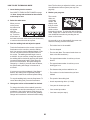
3. Start the walking belt and adjust the speed.
Touch the Start button on the screen or press the
Start button on the console to start the walking
belt. You can also press the Manual button on the
console, and then touch the Resume button on
the screen. The walking belt will begin to move
at 2 Km/H. As you exercise, change the speed of
the walking belt as desired by pressing the Speed
increase and decrease buttons. Each time you
press one of the buttons, the speed setting will
change by 0.1 Km/H; if you hold down the button,
the speed setting will change in increments of
0.5 Km/H.
If you press one of the numbered 1 Step Speed
buttons, the walking belt will gradually change
speed until it reaches the selected speed setting.
To stop the walking belt, press the Stop button. To
restart the walking belt, press the Start button.
4. Change the incline of the treadmill as desired.
To change the incline of the treadmill, press the
Incline increase and decrease buttons or one of the
numbered 1 Step Incline buttons. Each time you
press one of the buttons, the incline will gradually
change until it reaches the selected incline setting.
Note: The rst time you adjust the incline, you must
rst calibrate the incline system (see step 4 on
page 26).
5. Monitor your progress.
The console
offers sev-
eral display
modes. The
display mode
that you select
will determine
which workout
information is shown. To select the desired display
mode, simply ick or slide the screen. You can also
view additional information by touching the red
boxes on the screen.
As you walk or run on the treadmill, the screen can
show the following workout information:
• The incline level of the treadmill
• The time elapsed
• The time left (Note: The manual mode does not
have a time left countdown.)
• The approximate number of calories you have
burned
• The approximate number of calories you are
burning per hour
• The distance that you have walked or run
• The number of vertical meters that you have
climbed
• The speed of the walking belt
• A track representing 400 m (1/4 mile)
• Your pace in minutes per mile
• Your current lap number
• Your heart rate (see step 6)
Page is loading ...
Page is loading ...
Page is loading ...
Page is loading ...
Page is loading ...
Page is loading ...
Page is loading ...
Page is loading ...
Page is loading ...
Page is loading ...
Page is loading ...
Page is loading ...
Page is loading ...
Page is loading ...
Page is loading ...
Page is loading ...
Page is loading ...
Page is loading ...
Page is loading ...
Page is loading ...
-
 1
1
-
 2
2
-
 3
3
-
 4
4
-
 5
5
-
 6
6
-
 7
7
-
 8
8
-
 9
9
-
 10
10
-
 11
11
-
 12
12
-
 13
13
-
 14
14
-
 15
15
-
 16
16
-
 17
17
-
 18
18
-
 19
19
-
 20
20
-
 21
21
-
 22
22
-
 23
23
-
 24
24
-
 25
25
-
 26
26
-
 27
27
-
 28
28
-
 29
29
-
 30
30
-
 31
31
-
 32
32
-
 33
33
-
 34
34
-
 35
35
-
 36
36
-
 37
37
-
 38
38
-
 39
39
-
 40
40


NordicTrack NETL18711.2 User manual
- Category
- Treadmills
- Type
- User manual
- This manual is also suitable for
Ask a question and I''ll find the answer in the document
Finding information in a document is now easier with AI
Related papers
-
NordicTrack T 23.0 Treadmill User manual
-
NordicTrack T 13.0 Treadmill User manual
-
-
-
-
-
-
-
-
Other documents
-
ProForm 910 ZLT - PETL10812 Owner's manual
-
-
-
ProForm PETL15717 Owner's manual
-
-
HealthRider HETL13914 H130T User manual
-
Reebok RBTL19013.0 User manual
-
-
-