Air King AK927 Operating instructions

Category
Space heaters
Type
Operating instructions

This manual is also suitable for

READ AND SAVE THESE INSTRUCTIONS
READ CAREFULLY BEFORE ATTEMPTING TO ASSEMBLE, INSTALL, OPERATE OR MAINTAIN THE PRODUCT DESCRIBED. PROTECT
YOURSELF AND OTHERS BY OBSERVING ALL SAFETY INFORMATION. FAILURE TO COMPLY WITH
INSTRUCTIONS COULD RESULT IN PERSONAL INJURY AND/OR PROPERTY DAMAGE!
RETAIN INSTRUCTIONS FOR FUTURE REFERENCE.
GENERAL SAFETY INFORMATION
When using electrical appliances, basic precautions
should always be followed to reduce the risk of fire,
electric shock and injury to person, including the following:
1. Read all instructions before installing or using exhaust fan.
2. Use this unit only in the manner intended by the manufacturer.
If you have questions, contact the manufacturer.
3. Before servicing or cleaning the unit, switch power off at
service panel and lock the service disconnecting means to
prevent power from being switched on accidentally. When
the service disconnecting means cannot be locked, securely
fasten a prominent warning device, such as a tag, to the
service panel.
4. Installation work and electrical wiring must be done by
qualified person(s) in accordance with all applicable codes
and standards, including fire-related construction.
5. Sufficient air is needed for proper combustion and exhausting
of gases through the flue (chimney) of fuel burning equipment
to prevent back drafting. Follow the heating equipment
manufacturer’s guideline and safety standards such as those
published by the National Fire Protection Association (NFPA)
and the American Society for Heating, Refrigeration, and Air
Conditioning Engineers (ASHRAE), and the local code authorities.
CAUTION: FOR GENERAL VENTILATING USE ONLY. DO
NOT USE TO EXHAUST HAZARDOUS OR EXPLOSIVE MATERIALS
AND VAPORS.
Models: AK917, AK927
www.airkinglimited.com
210575917 Rev. A 1-06
Bulb Heat Lamp with Fan
SAVE THESE INSTRUCTIONS
6. When cutting or drilling into wall or ceiling, do not damage
electrical wiring and other hidden utilities.
7. Ducted fans must always be vented to the outdoors.
8. This unit must be grounded.
9. To avoid motor bearing damage and noisy and/or unbalanced
impellers, keep drywall spray, construction dust, etc. off
power unit.
WARNING: TO REDUCE THE RISK OF FIRE, ELECTRIC SHOCK,
DO NOT USE THIS FAN WITH ANY SOLID-STATE SPEED CONTROL
DEVICE.
WARNING: DO NOT INSTALL OVER A TUB OR MOUNT IN
A SHOWER STALL ENCLOSURE.
10. Do not install into a ceiling thermally insulated to a value
greater than R-40.
11. NEVER place a switch where it can be reached from a tub or
shower.
WARNING: DO NOT USE IN KITCHENS.
WARNING: THIS UNIT IS DESIGNED AND TESTED TO BE
A SUPPLEMENTAL HEATER FOR USE WITH A TIMER OR A
SWITCH. IT IS NOT INTENDED TO BE USED AS THE PRIMARY
SOURCE OF HEAT AND CONTROLLED BY A THERMOSTAT.
IMPORTANT INSTRUCTIONS -
OPERATING MANUAL
1 of 8
SECTION 3
Existing Construction
1. Set housing in position between the joist and trace an outline onto
the ceiling material (Figure 4). Set housing aside and cut opening,
being careful not to cut or damage any electrical or other hidden
utilities. Install the rails on the housing and position the housing in
the previously cut hole so that it is flush with the finished ceiling.
Secure the ends of the rails to the joists with screws or nails (not
provided) to ensure proper installation (Figure 3).
SECTION 4
Ducting
CAUTION: ALL DUCTING MUST COMPLY WITH LOCAL AND
NATIONAL BUILDING CODES.
1. Remove any tape that might be holding the damper in place during
shipping and connect the ducting to the fan’s duct collar (Figure
5). Secure in place using tape or screw clamp. Always duct the
fan to the outside through a wall or roof cap.
SECTION 5
Wiring
CAUTION: MAKE SURE POWER IS SWITCHED OFF AT SERVICE
PANEL BEFORE STARTING INSTALLATION.
CAUTION: ALL ELECTRICAL CONNECTIONS MUST BE MADE
IN ACCORDANCE WITH LOCAL CODES, ORDINANCES, OR NATIONAL
ELECTRICAL CODE. IF YOU ARE UNFAMILIAR WITH METHODS OF
INSTALLING ELECTRICAL WIRING, SECURE THE SERVICES OF A
QUALIFIED ELECTRICIAN.
1. Wiring Fan/Heat Bulb(s) Independently: Run wiring from an
approved wall switch carrying the appropriate rating. One neutral
(white), one ground (green or bare copper), and two hot (black and
blue). Secure the electrical wires to the housing with an approved
electrical connector. Make sure you leave enough wiring in the
box to make the connection to the fan’s receptacle.
1a. From where you have access to inside the fan’s junction box,
connect the white wire from the house to the white wire from the
fan. Connect one hot (black) wire from the house to the black wire
from the fan (this is the fan control). Connect the second hot (blue)
INSTALLATION INSTRUCTIONS
CAUTION:
MAKE SURE POWER IS SWITCHED OFF AT SERVICE
PANEL BEFORE STARTING INSTALLATION.
SECTION 1
Preparing the Unit
1. Unpack fan from the carton and confirm that all pieces are present.
In addition to the unit you should have:
1 - Grill
4 - Mounting Rails
1 - Instruction/Safety Sheet
2. Remove the wire compartment cover by loosening the two screws
holding the cover in place (Figure 1).
WARNING: DO NOT INSTALL OVER A TUB OR MOUNT IN A
SHOWER STALL ENCLOSURE.
3. Choose the location for your unit. To ensure the best air and sound
performance, it is recommended that the length of ducting and the
number of elbows be kept to a minimum, and that insulated hard
ducting be used. Larger duct sizes will reduce noise and airflow
restrictions. This fan will require at least 6" of clearance in the
ceiling, and will mount through drywall
up to 3/4" thick. The fan mounts between
16" on center joists using the provided
mounting rails.
4. Select the most convenient electrical
knockout and remove using a straight-
blade screw driver (Figure 2).
SECTION 2
New Construction
1. Install the rails on the housing and position the housing next to the
joist. Line up housing so it will be flush with the finished ceiling.
Secure the ends of the rails with screws or nails (not included) to
the joists and slide housing into final position (Figure 3).
www.airkinglimited.com
210575917 Rev. A 1-06 2 of 8
Figure 4
Figure 5
Figure 1
Screws
Wire
Compartment
Cover
Figure 2
Figure 3
Joist
Housing
Mounting Rails
2. Remove grill from carton and attach springs from grill to posts on
either side of housing (Figure 9).
5. Install a 250 watt maximum, R-40 Type A heat lamp (not included)
into the socket and center the grill around the lamp.
NOTE: Model AK927 uses 2 - 250 watt maximum R-40, Type A heat lamps.
6. Restore power and test your installation.
SECTION 7
Use and Care
CAUTION: MAKE SURE POWER IS SWITCHED OFF AT SERVICE
PANEL BEFORE SERVICING THE UNIT.
CAUTION: ALLOW LAMP(S) TO COOL BEFORE CLEANING THE
UNIT OR REPLACING THE LAMPS.
1. Cleaning the Grill: Remove heat lamp(s) and detach grill springs
from posts to release grill from housing. Use a mild detergent, such
as dishwashing liquid, and dry with a soft cloth. NEVER USE ANY
ABRASIVE PADS OR SCOURING POWDERS. Completely dry grill
before reinstalling. Refer to instructions in Section 6
Completing
the Installation
, to reinstall grill.
2. Cleaning the Fan Assembly: Wipe all parts with a dry cloth or gently
vacuum the fan. NEVER IMMERSE ELECTRICAL PARTS IN WATER.
CAUTION: ALLOW LAMP(S) TO COOL BEFORE REPLACING.
3. Changing the Heat Lamps: Disconnect power to the unit. Unscrew
heat lamp(s) from lamp holder and replace with 250 watt maximum,
R-40, type A heat lamp.
www.airkinglimited.com
210575917 Rev. A 1-06 3 of 8
Figure 9
wire from the house to the blue wire from the fan (this is the heat
bulb control). Connect the ground wire from the house to the green
wire from the fan (Figure 6). Use approved methods for all connections.
NOTE: On model AK927 connect the Hot (Blue) wire from the house to
the two Blue wires from the unit.
2. Wiring Fan/Heat Bulb together: Run wiring from an approved wall
switch carrying the appropriate rating. One neutral (white), one
ground (green or bare copper), and one hot (black). Secure the
electrical wires to the housing with an approved electrical
connector. Make sure you leave enough wiring in the box to make
the connection to the fan’s receptacle.
2a. From where you have access to inside the fan’s junction box,
connect the one white wire from the house to the white wire from
the fan. Connect the black wire from the house to both the black
and blue wires from the fan. Connect the ground wire from the
house to the green wire from the fan (Figure 7). Use approved
methods for all connections.
NOTE: On model AK927 connect the hot (black) wire from the house to
the black and two blue wires from the unit.
3. Reinstall the wire compartment cover using the two screws removed
in Step 2 of SECTION 1
Preparing the Unit
. Make sure all wires are
tucked inside of the compartment and are not being pinched or
showing through.
SECTION 6
Completing the Installation
1. Insert plug from fan into the receptacle located under the light
socket (Figure 8).
Figure 6
Ground
Supply from house
White
Hot (Black)
From Fan
Hot (Blue)
Figure 7
Ground
Supply from house
White
Hot (Black)
From Fan
Hot (Blue)
Figure 8
Posts
Springs
Grill
www.airkinglimited.com
210575917 Rev. A 1-06 4 of 8
LIMITED WARRANTY
All products manufactured by Air King Limited are warranted for one year from the date of purchase against defects in workmanship and/or material. In addition,
all ventilating/exhaust fans, heaters, combination fan lights and/or heaters, and range hoods are guaranteed for five years from the date of purchase against
defects in workmanship and/or material.
This warranty does not cover any labor or shipping costs or the cost of replacement components as part of routine maintenance such as: range hood grease
filters, charcoal filters or combination charcoal/grease filters; replacement light bulbs in range hoods or bathroom fan/light/bulb heater combinations. As well,
any damage or failure caused by abuse, misuse, abnormal usage, faulty installation, or improper maintenance will not be covered by this warranty.
In order to make a claim on this warranty, you must be the original consumer of the product. You will be required to present to Air King the original bill of sale
showing: date of purchase, place of purchase and model purchased. Failure to meet these requirements will void your warranty.
Air King will not be held responsible for any bodily injury or damages to personal property or real estate whether caused directly or indirectly by the product.
Some states and provinces do not allow the exclusion or limitation of incidental or consequential damages and some states do not allow limitations on how
long an implied warranty lasts, so these exclusions or limitations may not apply to you. This warranty gives you specific legal rights and you may have other
rights which vary from state to state and province to province.
FOR PARTS OR TECHNICAL ASSISTANCE
Please call: 1-800-465-7300, MONDAY THROUGH FRIDAY, BETWEEN THE HOURS OF 8 AM AND 4:00 PM EST.
PLEASE DO NOT RETURN PRODUCT TO PLACE OF PURCHASE.
Reference the type and style of product (located on label inside of the product) when you call.
For more information please visit our website: wwwairkinglimited.com
Installer: _________________________________________________________ Installation Date:_________________________________________
Place of Purchase: _________________________________________________ Model Number: __________________________________________
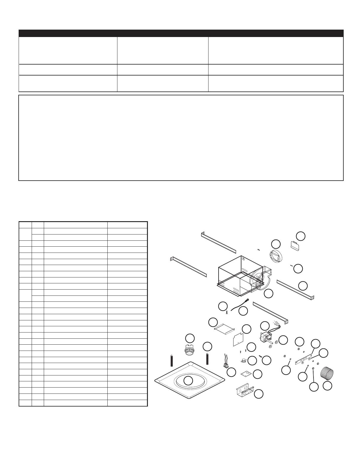
# Qty. Description Replacement Part #
1 1 AK917 Fan Housing 5S3402080
1 AK927 Fan Housing 5S3402090
2 4 Mounting Rails 5S1299002
3 1 Collar 5S3402041
4 1 Damper 5S3402042
5 1 Overheat Protector 5S3402081
6 1 Mounting Plate Over Heat 5S3402082
7 1* Mounting Plate Lamp Holder 5S3402083
8 1* Lamp Holder 5S3402084
9 2 Grill Springs 5S3402085
10 1 AK917 Grill 5S3402086
1 AK927 Grill 5S3402091
11 1 Internal Wire Cover 5S3402087
12 1 External Wire Cover 5S3402088
13 2 Nut 5S3402045
14 2 Spacer 5S3402044
15 1 Motor 5S3402043
16 2 Lockwasher 5S3402046
17 1 Motor Bracket 5S3402047
18 2 Washer 5S3402048
19 2 Lockwasher 5S3402049
20 2 Hex Nut 5S3402050
21 1 Blower Wheel 5S3402051
22 1 14 ga Ground Wire 5S1999003
23 1 #10 Ground Screw 5S1999002
24 2 #8 Screw 5S1999004
25 2 Screw 5S3402064
26 2 Screw - Collar 5S3402040
27 1 Polarized Receptacle 5S3402089
Troubleshooting Guide
Trouble Probable Cause Suggested Remedy
1. Fan and/or lamps do not operate when switch is on. 1a. A fuse may be blown or a circuit tripped. 1a. Replace fuse or reset circuit breaker.
1b. Connector plug from motor is not plugged in. 1b. Turn off power to unit. Remove Grill and plug motor into receptacle
in housing. Restore power to unit.
1c. Wiring is not connected properly. 1c. Turn off power to unit. Check that all wires are connected.
1d. Motor has stopped operating. 1d. Replace motor.
2. Fan is operating, but air moves slower than normal. 2. Obstruction in the exhaust ducting. 2. Check for any obstructions in the ducting. The most common are bird nests
in the roof cap or wall cap where the fan exhausts to the outside.
3. Fan is operating louder than normal. 3a. Motor is loose. 3a. Turn off power to unit. Remove grill and check that all screws are fully
tightened. Restore power to unit.
3b. Fan blade is hitting housing of unit. 3b. Call your dealer for service.
* Model AK927 quantity - 2
1
2
3
4
5
6
7
8
9
10
11
12
13
14
15
16
17
18
19
20
21
22
23
24
25
26
27
  • Page 1 1
  • Page 2 2
  • Page 3 3
  • Page 4 4
  • Page 5 5
  • Page 6 6
  • Page 7 7
  • Page 8 8

Air King AK927 Operating instructions

Category
Space heaters
Type
Operating instructions
This manual is also suitable for

Ask a question and I''ll find the answer in the document

Finding information in a document is now easier with AI

in other languages