Nota:
• Antes de finalmente instalar la unidad, conecte el
cableado temporalmente y compruebe que las
conexiones están correctas e que el sistema fun-
ciona debidamente.
• Utilice sólo las piezas que se incluyen con esta
unidad para asegurar la instalación adecuada. El
uso de piezas no autorizadas podría causar fallos
de funcionamiento.
• Consulte con su distribuidor si la instalación
requiere del taladro de orificios u otras modifica-
ciones del vehículo.
• Instale la unidad donde no alcance el espacio del
conductor, y donde no pueda dañar a los
pasajeros si sucediera un paro repentino, como
una detención de emergencia.
• El semiconductor láser se dañará si se sobre-
calienta, por eso no instale la unidad en un lugar
caliente – por ejemplo, cerca de la salida de un
calefactor.
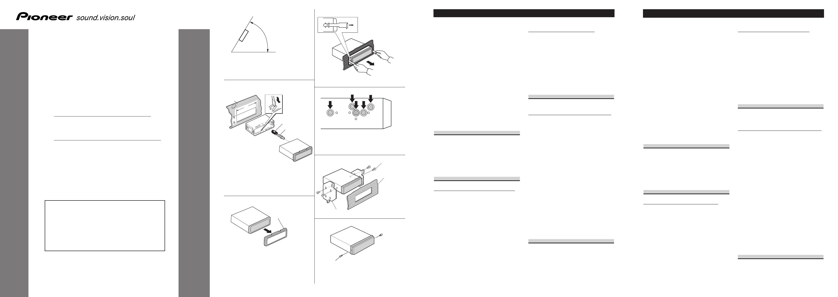
• Si el ángulo de la instalación excede los 60° del
lado horizontal, la unidad podría no brindar su
óptimo funcionamiento. (Fig. 1)
Montaje delantero/trasero DIN
Esta unidad quede instalarse correstamente de la
“Delantera” (montaje delantero DIN conven-
ciona) o “Trasera” (montaje trasero DIN, utilizan-
do los tornillos roscados en los constados del cha-
sis de la unidad). Para detalles, refiérase a los
métodos de instalación ilustrados abajo.
Montaje delantero DIN
Instalación con tope de goma (Fig. 2)
1. Tablero de instrumentos
2. Soporte
Después de insertar el soporte en la tabla de
mandos, luego seleccione las orejetas apropiadas
según el grosor del material de la tabla de man-
dos y dóblelos.
(Instale lo más firme posible usando las lengüe-
tas superior e inferior. Para fijar, doble las
lengüetas 90 grados.)
3. Tope de goma
4. Tornillo
Quitado de la unidad (Fig. 3) (Fig. 4)
5. Marco
Para extraer marco, extienda las partes superior e
inferior del marco hacia fuera para soltarlo. (Para
la fijación del marco, apunte el lado con ranura
hacia abajo.)
• Suelte el painel delantero para facilitar la
extracción del marco.
6. Inserte las herramientas de extracción suminis-
tradas en la unidad, como se indica en la figura,
hasta que se enganchen en su positión.
Tire de la unidad mientras mantiene las her-
ramientas presionadas contra los lados de la
unidad.
Montaje trasero DIN
Instalación usando los agujeros para
tornillos ubicados en ambos costados de
la unidad (Fig. 3) (Fig. 5) (Fig. 6)
1. Quite el marco.
5. Marco
Para extraer marco, extienda las partes superior e
inferior del marco hacia fuera para soltarlo. (Para
la fijación del marco, apunte el lado con ranura
hacia abajo.)
• Suelte el painel delantero para facilitar la
extracción del marco.
2. Fijación de la unidad a la ménsula
de montaje existente.
7. Seleccione una posición en la que los orificios
para los tornillos del soporte y del de la unidad
principal queden alineados, y apriete los tornillos
en 2 lugares de un lado. Utilice ya sea los tornil-
los de fijación (5 × 8 mm) o los tornillos a paño
(5 × 9 mm), dependiendo de la forma de los ori-
ficios de tornillo en la ménsula.
8. Tornillo
9. Ménsula de montaje de radio existente
10. Tablero de instrumentos o consola
Sobre los tornillos de fijación del
panel delantero (Fig. 7)
11. Tornillos de fijación
Si no desea utilizar la función de extracción y
colocación del panel delantero, utilice los tornil-
los de fijación suministrados y fije el panel
delantero a esta unidad.
Instalación <ESPAÑOL>
Note:
• Before making a final installation of the unit,
temporarily connect the wiring to confirm that
the connections are correct and the system works
properly.
• Use only the parts included with the unit to
ensure proper installation. The use of unautho-
rized parts can cause malfunctions.
• Consult with your nearest dealer if installation
requires the drilling of holes or other modifica-
tions of the vehicle.
• Install the unit where it does not get in the dri-
ver’s way and cannot injure the passenger if there
is a sudden stop, like an emergency stop.
• The semiconductor laser will be damaged if it
overheats, so don’t install the unit anywhere hot
— for instance, near a heater outlet.
• If installation angle exceeds 60° from horizontal,
the unit might not give its optimum performance.
(Fig. 1)
DIN Front/Rear-mount
This unit can be properly installed either from
“Front” (conventional DIN Front-mount) or
“Rear” (DIN Rear-mount installation, utilizing
threaded screw holes at the sides of unit chassis).
For details, refer to the following illustrated
installation methods.
DIN Front-mount
Installation with the rubber bush (Fig. 2)
1. Dashboard
2. Holder
After inserting the holder into the dashboard,
then select the appropriate tabs according to the
thickness of the dashboard material and bend
them.
(Install as firmly as possible using the top and
bottom tabs. To secure, bend the tabs 90
degrees.)
3. Rubber bush
4. Screw
Removing the Unit (Fig. 3) (Fig. 4)
5. Frame
To remove the frame, extend top and bottom of
the frame outwards in order to unlock it. (When
reattaching the frame, point the side with a
groove downwards and attach it.)
• It becomes easy to remove the frame if the
front panel is released.
6. Insert the supplied extraction keys into the unit,
as shown in the figure, until they click into place.
Keeping the keys pressed against the sides of the
unit, pull the unit out.
DIN Rear-mount
Installation using the screw holes on the
side of the unit (Fig. 3) (Fig. 5) (Fig. 6)
1. Remove the frame.
5. Frame
To remove the frame, extend top and bottom of
the frame outwards in order to unlock it. (When
reattaching the frame, point the side with a
groove downwards and attach it.)
• It becomes easy to remove the frame if the
front panel is released.
2. Fastening the unit to the factory
radio mounting bracket.
7. Select a position where the screw holes of the
bracket and the screw holes of the head unit
become aligned (are fitted), and tighten the
screws at 2 places on each side. Use either truss
screws (5 × 8 mm) or flush surface screws
(5 × 9 mm), depending on the shape of the screw
holes in the bracket.
8. Screw
9. Factory radio mounting bracket
10. Dashboard or Console
About the fixing screws for the
front panel (Fig. 7)
11. Fixing screw
If you do not operate the Removing and
Attaching the Front Panel Function, use the sup-
plied fixing screws and fix the front panel to this
unit.
Installation <ENGLISH>
INSTALLATION MANUAL
MANUEL D’INSTALLATION
<KMMZX> <04J00000>
DEH-4700MP
DEH-4700MPB
Printed in
Imprimé
<URD3849-A> EW
This product conforms to new cord colors.
Los colores de los cables de este producto se confor-
man con un nuevo código de colores.
Dieses Produkt entspricht den neuen Kabelfarben.
Le code de couleur des câbles utilisé pour ce produit
est nouveau.
Questo prodotto è conforme ai nuovi codici colori.
De kleuren van de snoeren van dit toestel zijn gewijzigd.
60°
Fig. 2
Abb. 2
Afb. 2
8
10
9
7
Fig. 1
Abb. 1
Afb. 1
Fig. 3
Abb. 3
Afb. 3
Fig. 4
Abb. 4
Afb. 4
Fig. 5
Abb. 5
Afb. 5
Fig. 6
Abb. 6
Afb. 6
Fig. 7
Abb. 7
Afb. 7
URD3849A Page 1

