Gigabyte 8I845GE-RZ Owner's manual

Category
Mixer/food processor accessories
Type
Owner's manual
- 1 -
English
Step
1
Installing a CPU and CPU Cooler
A. Installing an Intel CPU (skip this step if the motherboard has a built-in CPU)
The sequence of installation may differ depending on the type of case and devices used. The
installation instructions below apply to GIGABYTE's desktop systems and are for reference
only.
Refer to the user's manual included for detailed motherboard specications.
Before installing the devices, make sure they are compliant with the connectors on your computer.
Before installing the devices, be sure to turn off the devices and your computer. Unplug the power cord
from the power outlet to prevent damage to the devices and the system components.
Place the computer system on a stable surface to prevent improper installation resulted from shaking.
Type B:
Push lever A (closest to the " " marking) down and away from the socket to release it. Then push
lever B (closest to the " " marking) down and away from the socket and lift it. Gently press lever A to
allow the load plate to rise. Open the load plate.
A-1 RefertothefollowinginstructionsbasedonyourCPUspecications:
Type A:
Lift the CPU socket lever and the metal load plate will be lifted as well.
a. If the protective socket cover is fastened on the CPU socket, remove
itrst.
b. If the protective socket cover is fastened on the metal load plate, do
not remove it at this stage. The socket cover may pop off from the
load plate automatically during the process of re-engaging the lever
after you insert the CPU.
For detailed instructions on installing the CPU, please refer to the user’s manual.
Lever A Lever B
A-2 HoldtheCPUwithyourthumbandindexngers.AligntheCPUpinonemarking(triangle)withthepin
one corner of the CPU socket (or you may align the CPU notches with the socket alignment keys) and
gently insert the CPU into position.
A-3 Once the CPU is properly inserted, replace the load plate and push the CPU socket lever back into its locked position.
Once the type B is properly inserted, carefully replace the load plate. Then secure lever B under its retention
tab. The socket cover may pop off from the load plate during the process of engaging the lever. Finally,
secure lever A under its retention tab to complete the installation of the CPU.
- 2 -
English
C-1 BeforeinstallingtheCPUcooler,pleaserstaddathinlayerof
heat sink paste on the surface of the CPU. Then install the cooler
(refer to the installation manual for your CPU cooler).
C-2 Connect the CPU cooler cable to the CPU_FAN connector located
on the motherboard so that the cooler can properly function to
prevent the CPU from overheating.
C. Installing the CPU Cooler
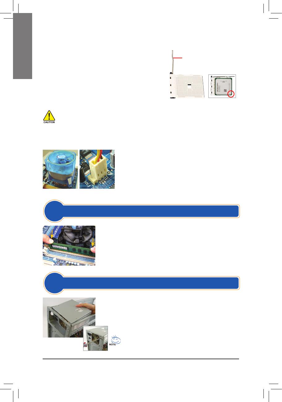
B. Installing an AMD CPU (skip this step if the motherboard has a built-in CPU)
Note the orientation of the memory module. Spread the retaining clips at both ends
of the memory socket. Place the memory module on the socket. As indicated in the
pictureontheleft,placeyourngersonthetopedgeofthememory,pushdownon
the memory and insert it vertically into the memory socket. The clips at both ends
of the socket will snap into place when the memory module is securely inserted.
Step
2
Installing Memory
Step
3
Preparing the Case and Installing a Power Supply
UsingtheGIGABYTEdesktopsystemasthedemonstrationexample,pleaserst
remove both sides and the lid of the case in order to install the power supply.
Place the power supply in the correct place in the case and secure it with screws.
Installation and placement of the power supply may differ depending on the type
of case used.
To ensure sufcient power can be supplied to your system, it is
recommended that a power supply of good quality be used. If a power
supply is used that does not provide the required power, the result can
lead to an unstable or unbootable system.
Do not force the CPU into the CPU socket. The CPU cannot t in if oriented incorrectly. Adjust the CPU
orientation if this occurs.
DO NOT touch socket contacts. To protect the CPU socket, always replace the protective socket cover
when the CPU is not installed.
CPU Socket Lever
Pin 1
CPU Socket
B-1 Completely raise the CPU socket lever. Align the CPU pin
one (small triangle marking) with the triangle marking on the
CPU socket and gently insert the CPU into the socket. Make
surethattheCPUpinstperfectlyintotheirholes.
B-2 OncetheCPUispositionedintoitssocket,placeonenger
down on the middle of the CPU, lowering the socket lever
and latching it into the fully locked position.
- 3 -
English
Remove the original I/O shield from the back of the case and replace it with the
motherboard I/O shield. Place the motherboard within the case by positioning it
into its I/O shield. Align the mounting screw holes on the motherboard with their
corresponding mounting holes on the case. Secure the motherboard in place
with screws.
Locate an expansion slot that supports your card and remove the slot cover from
the case back panel. Then insert the expansion card into the slot. Secure the
expansion card's bracket to the case back panel with a screw.
I/O Shield
Before purchasing an expansion card, check the length of the card, making
sure it can t into your case.
Make sure that the expansion card is fully seated in its slot.
Step
4
Installing the Motherboard
Step
5
Installing an Expansion Card
PCI Express Graphics Card
6-1 Install your optical drives, such as DVD-ROM and CD-ROM drives.
Remove the 5.25" drive bay cover from the front of the case. Mount the optical drive
in the 5.25" drive bay and secure it with screws.
6-2 Install your IDE and SATA hard drives.
Install the hard drive into a drive bay within the case and secure it with screws.
One motherboard IDE connector can connect up to two IDE devices. Prior to installation, check the jumper
settings (master and slave) on your IDE devices.
If more than one hard drive is installed, enter system BIOS Setup to set the hard drive boot sequence.
Installing an Optical Drive
Installing a Hard Drive
Step
6
Installing IDE and SATA Devices
- 4 -
English
7-1 Connect cables to internal connectors and headers on the motherboard, including IDE/SATA
connectors, and front panel audio, USB, IEEE 1394 headers, etc.
7-2 Attach the front panel module (differs depending on the case design, consisting of power
indicator, hard drive activity indicator, speakers, reset switch, power switch, etc.) from the case
to the front panel header (F_PANEL) on the motherboard.
Front Panel Header
MSG: Message/Power/Sleep LED
PWR: Power LED
PW: Power Switch
SPEAK: Speaker
HD: Hard Drive Activity LED
RES: Reset Switch
CI: Chassis Intrusion Header
Once the steps above have been completed, connect
the peripheral devices to the computer, such as the
keyboard, mouse, monitor, etc. Then connect the power,
turn on the system, and install all required software.
Power Supply Power Switch
PS/2 Keyboard Port
Power Cord Connector
DVI-D Port
PS/2 Mouse Port
HDMI Port D-Sub Port
eSATA Port
S/PDIF Connector
IEEE 1394 Port USB Ports
Audio Jacks RJ-45 LAN Port
External Graphics Card
Step
7
Connecting Cables to Internal Connectors
Step
8
Connecting Peripherals
Back Panel of the Case
(Note) The pin assignments for the front panel header may differ by model. Refer
to the motherboard user's manual for the actual pin assignments.
1
2
PinAssignmentsA:
19
20
+MSG-
+HD-
+PW-
-CI+-RES+ +PWR-
+SPEAK-
PinAssignmentsB:
+MSG-
+HD- -RES+
NC
+PW- +SPEAK-
  • Page 1 1
  • Page 2 2
  • Page 3 3
  • Page 4 4
  • Page 5 5
  • Page 6 6
  • Page 7 7
  • Page 8 8
  • Page 9 9
  • Page 10 10
  • Page 11 11
  • Page 12 12
  • Page 13 13
  • Page 14 14
  • Page 15 15
  • Page 16 16
  • Page 17 17
  • Page 18 18
  • Page 19 19
  • Page 20 20
  • Page 21 21
  • Page 22 22
  • Page 23 23
  • Page 24 24
  • Page 25 25
  • Page 26 26
  • Page 27 27
  • Page 28 28
  • Page 29 29
  • Page 30 30
  • Page 31 31
  • Page 32 32
  • Page 33 33
  • Page 34 34
  • Page 35 35
  • Page 36 36
  • Page 37 37
  • Page 38 38
  • Page 39 39
  • Page 40 40
  • Page 41 41
  • Page 42 42
  • Page 43 43
  • Page 44 44
  • Page 45 45
  • Page 46 46
  • Page 47 47
  • Page 48 48
  • Page 49 49
  • Page 50 50
  • Page 51 51
  • Page 52 52
  • Page 53 53
  • Page 54 54
  • Page 55 55
  • Page 56 56
  • Page 57 57
  • Page 58 58
  • Page 59 59
  • Page 60 60
  • Page 61 61
  • Page 62 62
  • Page 63 63
  • Page 64 64
  • Page 65 65
  • Page 66 66
  • Page 67 67
  • Page 68 68
  • Page 69 69
  • Page 70 70
  • Page 71 71
  • Page 72 72

Gigabyte 8I845GE-RZ Owner's manual

Category
Mixer/food processor accessories
Type
Owner's manual

Ask a question and I''ll find the answer in the document

Finding information in a document is now easier with AI