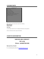
Falcon F900 SERIES User, Installation And Servicing Instructions
- Type
- User, Installation And Servicing Instructions
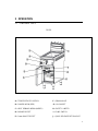
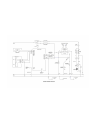
Falcon F900 SERIES is a professional deep fryer designed for use in commercial kitchens. It features precise temperature control, a high-power burner for rapid heat-up, and a built-in filtration system to keep cooking oil clean. The F900 SERIES is ideal for frying a variety of foods, including French fries, chicken, fish, and vegetables.
Falcon F900 SERIES is a professional deep fryer designed for use in commercial kitchens. It features precise temperature control, a high-power burner for rapid heat-up, and a built-in filtration system to keep cooking oil clean. The F900 SERIES is ideal for frying a variety of foods, including French fries, chicken, fish, and vegetables.


-
 1
1
-
 2
2
-
 3
3
-
 4
4
-
 5
5
-
 6
6
-
 7
7
-
 8
8
-
 9
9
-
 10
10
-
 11
11
-
 12
12
-
 13
13
-
 14
14
-
 15
15
-
 16
16
-
 17
17
-
 18
18
-
 19
19
-
 20
20
-
 21
21
-
 22
22
-
 23
23
-
 24
24
-
 25
25
-
 26
26
-
 27
27
-
 28
28
-
 29
29
-
 30
30
-
 31
31
-
 32
32
-
 33
33
-
 34
34
-
 35
35
-
 36
36
-
 37
37
-
 38
38


Falcon F900 SERIES User, Installation And Servicing Instructions
- Type
- User, Installation And Servicing Instructions
Falcon F900 SERIES is a professional deep fryer designed for use in commercial kitchens. It features precise temperature control, a high-power burner for rapid heat-up, and a built-in filtration system to keep cooking oil clean. The F900 SERIES is ideal for frying a variety of foods, including French fries, chicken, fish, and vegetables.
Ask a question and I''ll find the answer in the document
Finding information in a document is now easier with AI
Related papers
-
Falcon F900 G9881 User, Installation And Servicing Instructions
-
-
-
Falcon G2845F Installation, Servicing And User Instructions Manual
-
Falcon G9084A User, Installation And Servicing Instructions
-
-
-
-
Falcon G3203 Owner's manual
-
Other documents
-
Whirlpool ADN625 User guide
-
ROLLER GRILL RFG 12 (GP318-P) Owner's manual
-
Bartscher 2859271 Operating instructions
-
Electrolux 9CHG584103 User manual
-
Bartscher 286917 Operating instructions
-
Pitco 14 User manual
-
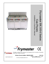 Frymaster BK1814 User manual
-
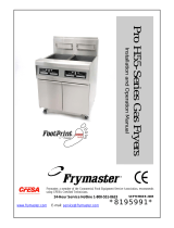 Frymaster Pro H55-Series User manual
-
 Frymaster FPH55 Operational Manual
-
 Frymaster H50 User manual


