Page is loading ...


TSM810C User's Manual
Page ii Revision 1.0
Revision History
Rev.
Description
1.0
Original document

Revision 1.0 Page iii
Table of Contents
1 General .......................................................................................................................................... 1
1.1 Introduction ........................................................................................................................ 1
1.2 Firmware Revision ............................................................................................................. 2
1.3 TSM810C Features ............................................................................................................ 2
1.4 Quick Install ........................................................................................................................ 2
2 Installation ...................................................................................................................................... 3
2.1 Unpacking the Box ............................................................................................................. 3
2.2 Choosing a Mounting Location ........................................................................................... 4
2.3 Mounting the TSM810C ..................................................................................................... 5
2.3.1 Mounting Considerations .............................................................................................. 5
2.3.2 Ergonomics ................................................................................................................... 5
2.3.3 Wall or Panel Mounting ................................................................................................. 6
2.3.4 Arm Mounting ............................................................................................................... 7
2.4 Connecting the TSM810C .................................................................................................. 9
2.4.1 LAN Connection .......................................................................................................... 10
2.4.2 USB Device Connection ............................................................................................. 11
2.4.3 Power Connection....................................................................................................... 11
2.4.4 NMEA 2000
®
Connection ............................................................................................ 13
2.5 Power Sequencing ........................................................................................................... 14
2.6 Configuring the TSM810C ................................................................................................ 15
2.6.1 Manually Entering LAN Connection Information ......................................................... 15
3 Operating the TSM810C .............................................................................................................. 18
3.1 Turning the TSM810C On ................................................................................................ 18
3.2 Turning the TSM810C Off ................................................................................................ 18
3.3 Adjusting the Screen Brightness on the TSM810C .......................................................... 18
3.4 Using the TSM810C ......................................................................................................... 18
4 Maintenance ................................................................................................................................ 19
5 Troubleshooting ........................................................................................................................... 20
6 Mechanical Drawings ................................................................................................................... 21
7 Technical Specifications .............................................................................................................. 22
8 Technical Support ........................................................................................................................ 24
9 Maretron (2 Year) Limited Warranty............................................................................................. 25

TSM810C User's Manual
Page iv Revision 1.0
Table of Figures
Figure 1 – TSM810C Network Diagram ................................................................................................ 1
Figure 2 – TSM810C Cutout Dimensions (not to scale) ........................................................................ 6
Figure 3 – TSM810C VESA Arm Mounting Retention Screws .............................................................. 8
Figure 4 – TSM810C VESA Arm Mounting Retention Screws .............................................................. 8
Figure 5 – TSM810C Bottom and Rear Panels ..................................................................................... 9
Figure 6 – LAN Connection ................................................................................................................. 10
Figure 7 – USB Device Connection .................................................................................................... 11
Figure 8 – Power Connections ............................................................................................................ 12
Figure 9 – Attaching Power Cables to Connector ............................................................................... 13
Figure 10 – NMEA 2000
®
Connector Face Views ............................................................................... 14
Figure 11 – TSM810C Startup Screen ................................................................................................ 15
Figure 12 – N2KView
®
Window with Tabs Displayed .......................................................................... 16
Figure 13 – Ethernet Dialog ................................................................................................................ 17

Revision 1.0 Page 1
1 General
1.1 Introduction
Congratulations on your purchase of the Maretron TSM810C Vessel Monitoring and Control
Touchscreen. Maretron has designed and built your display to the highest standards for years of
dependable and accurate service.
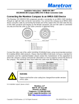
The TSM810C is an 8” dedicated touchscreen that includes Maretron’s N2KView
®
vessel monitoring
and control software. The N2KView
®
software allows you to configure as many favorite screens as
you want with exactly the information you want to see. The TSM810C provides an extremely simple
touch interface for monitoring and controlling critical systems from anywhere on the vessel.
The TSM810C is ruggedized for marine use and includes a solid-state disk drive to withstand the
pounding associated with waves. And since the TSM810C dissipates less than 10 watts, there is no
need for internal cooling fans that are noisy and wear out causing electronics to overheat and fail.
The TSM810C can be mounted outside given the high bright screen and waterproof front.
As an alternative to controlling the TSM810C through the touch screen, the TSM810C includes two
USB ports for connecting keyboards, mice, or trackballs. The TSM810C also has an Ethernet port for
connecting Internet Protocol (IP) cameras for viewing within the N2KView
®
software. Lastly, the
TSM810C contains two completely isolated CAN bus connectors (M12) for easy connection to single,
dual, or redundant NMEA 2000
®
networks.
Optional
USB Keyboard
Or Mouse
Engine
Monitor
Battery
Monitor
Electrical
Panel
Tank
Monitor
NMEA 2000
Network
TSM810C
C
Figure 1 – TSM810C Network Diagram

TSM810C User's Manual
Page 2 Revision 1.0
The Maretron TSM810C is designed to operate within the harsh demands of the marine environment.
However, no piece of marine electronic equipment can function properly unless installed, configured,
and maintained in the correct manner. Please read carefully and follow these instructions for
installation, configuration, and usage of the Maretron TSM810C to ensure optimal performance.
1.2 Firmware Revision
This manual corresponds to the TSM810C running N2KView
®
Version 6.0.3.
1.3 TSM810C Features
The Maretron TSM810C has the following features:
• 8” TFT LCD Panel, LED Backlit
• Widescreen Aspect Ratio 5:3
• 800 x 480 Pixels
• 1350 nits Brightness (Optically Bonded)
• Solid State Disk Drive
• Fanless Cooling System
• Flush mounting hardware included
• Optional VESA mounting capability
• All N2KView licenses included
• 2 isolated NMEA 2000
®
connectors for direct connection to single or dual NMEA 2000
®
networks
1.4 Quick Install
Installing the Maretron TSM810C display involves the following five steps. Please refer to the
individual sections for additional details.
• Unpacking the Box (Section 2.1)
• Choosing a Mounting Location (Section 2.2)
• Mounting the TSM810C (Section 0)
• Connecting the TSM810C (Section 0)
• Configuring the TSM810C (Section 0)

Revision 1.0 Page 3
2 Installation
2.1 Unpacking the Box
When unpacking the box containing the Maretron TSM810C, you should find the following items:
• 1 – TSM810C 8” Vessel Monitoring and Control Touchscreen
• 2 – Snap On Bezels
• 1 – Blue Maretron USB Drive Containing (among other documents)
o 1 – TSM810C User’s Manual
o 1 – N2KView
®
Documentation
• 1 – 1m USB Cable with Waterproof Bulkhead Connector
• 1 – Warranty Registration Card
If any of these items are missing or damaged, please contact Maretron.
NOTE
To prevent damage to chassis corners and/or breaking front glass, please review
the illustrations below before handling the TSM810C.

TSM810C User's Manual
Page 4 Revision 1.0
2.2 Choosing a Mounting Location
The TSM810C front panel is splash proof (IEC IP66 rating – protected against the effects of powerful
water jets), while the rear of the TSM810C is drip proof (IEC IP22 rating – protected against the
effects of dripping water when tilted up to 15°). The TSM810C may be mounted either in an indoor or
outdoor location.
Adequate ventilation is a necessary prerequisite for the life of the product. The air inlet and outlet
openings must definitely be kept clear; coverings which restrict ventilation are not permissible.
Generally, do not install the unit in a horizontal position (laying down), as this will cause heat to build
up inside the unit which will damage the LCD Panel. To prevent this problem, we recommend
installing the unit in a vertical position (±30 degrees) to improve the airflow through the unit.
To further improve the cooling of the unit, we recommend installing Cooling Fans underneath blowing
upwards into the unit air inlet. This may be required in high temperature applications and also when
there is reason to expect temperature problems due to non-optimal way of mounting.
Exposure to extreme direct sunlight can cause a considerable increase in the temperature of the unit,
and might under certain circumstances lead to over temperature. This point should already be taken
into consideration when the bridge equipment is being planned (sun shades, distance from the
windows, ventilation, etc.).
Space necessary for ventilation, for cable inlets, for the operating procedures and for maintenance,
must be provided. The NMEA 2000 cables require at least 140mm (5.5”) clearance from the back
surface of the TSM810C for the plug and cable minimum bend radius. If a 90° field attachable
connector is used on the cable, then this can be reduced to 51mm (2”)
Proper strain relieve should be installed on cables attached to the TSM810C so that cable breaks will
not occur, e.g. during service work.
Do not paint the product. The surface treatment influences on the excess heat transfer. Painting,
labels or other surface treatments that differ from the factory default, might cause overheating.
Expose to heavy vibration and acoustic noise might under certain circumstances affect functionality
and expected lifetime. This must be considered during system assembly and installation. Mounting
position must carefully be selected to avoid any exposure of amplified vibration.

Revision 1.0 Page 5
2.3 Mounting the TSM810C
The TSM810C has two mounting options, which include:
• Wall/Panel mounting
• Arm mounting (requires purchase of a VESA 75mm mounting arm)
2.3.1 Mounting Considerations
The useful life of the components of all Electronics Units generally decreases with increasing ambient
temperature; it is therefore advisable to install such units in air-conditioned rooms. If there are no
such facilities, these rooms must at least be dry, adequately ventilated and kept at a suitable
temperature in order to prevent the formation of condensation inside the display unit.
Since the TSM810C is fanless, cooling takes place via the surface of the casing. The cooling must
not be impaired by partial covering of the unit or by installation of the unit in a confined cabinet.
In the area of the wheel house, the distance of each electronics unit from the magnetic standard
compass or the magnetic steering compass must not be less than the permitted magnetic protection
distance. This distance is measured from the center of the magnetic system of the compass to the
nearest point on the corresponding unit concerned.
Units which are to be used on the bridge wing must be installed inside the “wing control console”
protected against the weather. In order to avoid misting of the viewing screen, a 25 ... 50 W console-
heating (power depending on the volume) is recommended.
When selecting the site of a display unit, the maximum cable lengths have to be considered.
When a product is being installed, the surface base or bulkhead must be checked to ensure that it is
flat in order to avoid twisting of the unit when the fixing screws are tightened, because such twisting
would impair mechanical functions. Any unevenness should be compensated for by means of
spacing-washers.
Transportation damage, even if apparently insignificant at first glance, must immediately be examined
and be reported to the freight carrier. The moment of setting-to-work of the equipment is too late, not
only for reporting the damage but also for the supply of replacements.
The classification is only valid for approved mounting brackets provided by Maretron. The unit shall
be mounted stand-alone without any devices or loose parts placed at or nearby the unit. Any other
type of mounting might require test and re-classification.
2.3.2 Ergonomics
Adjust the unit height so that the top of the screen is at or below eye level. Your eyes should look
slightly downwards when viewing the middle of the screen.
Adjust screen inclination to remain gaze angle to the center of the screen approximately
perpendicular to the line of gaze.

TSM810C User's Manual
Page 6 Revision 1.0
When products are to be operated both from a sitting position and from a standing position, a screen
inclination of about 30° to 40° (from a vertical plane) has turned out to be favorable.
The brightness of displays is limited. Sunlight passing directly through the bridge windows - or its
reflection – which falls upon the screen workplaces must be reduced by suitable means (negatively
inclined window surfaces, venetian blinds, distance from the windows, dark coloring of the deckhead).
These units are equipped with optical enhanced technology to reduce reflections and are viewable in
direct sun light, but as a general rule the units at the bridge wing area is recommended to be installed
or mounted by suitable alignment or bulkhead /deckhead mounting in such a way that reflections of
light from the front panel of the display are not directed into the observer’s viewing direction.
The use of ordinary commercial filter plates or filter films is not permitted for items of equipment that
require approval (by optical effects, “aids” of that kind can suppress small indicators, for example).
2.3.3 Wall or Panel Mounting
Mounting the TSM810C on a wall or panel requires a cutout in the wall or panel. Please ensure there
is sufficient space behind the unit to connect the NMEA 2000 cables. Typically they require 190mm
(7.5”) for a straight connector, or 102mm (4”) for a right angle connector, measured from the front
face of the wall or panel.
Figure 2 – TSM810C Cutout Dimensions (not to scale)
Step 1: Select the position on the panel or wall to mount the TSM810C.

Revision 1.0 Page 7
Step 2: Cut out a section from the panel that corresponds to the rear panel dimensions of the
TSM810C. Take care that the panel section that is cut out is smaller than the overall size of
the front panel of the TSM810C but just large enough for the rear panel of the TSM810C to fit
through, according to the dimensions in Figure 2 above.
Step 3: Slide the TSM810 through the hole from the front until the frame is flush against the panel
and then mark the positions of the 6 mounting holes. Remove the TSM810 before drilling the
holes.
Step 4: Drill six 5.5mm holes for the mounting screws according to the dimensions in Figure 2 above.
Step 5: Slide the TSM810C through the hole until the frame is flush against the panel.
Step 6: From the front of the panel, place six #10 flat/countersunk bolts through the
TSM810C frame and the panel, add washers and nuts, and tighten until the
display is firmly secured to the panel. Suitable #10 countersunk screws may be
used in place of the bolts for wall mounting. The bolts and screws are not
provided by Maretron.
Step 7: Clip the two bezels on to the front of the TSM810, hiding the screws.
2.3.4 Arm Mounting
The TSM810C is VESA (Video Electronics Standards Association) compliant and can be mounted on
an arm with a 75mm interface pad. To mount the TSM810C on an arm, please follow the steps below.
NOTE
When purchasing a mounting arm please ensure that it is VESA compliant and that
the arm has a 75 mm interface pad. If it is not VESA compliant, it cannot be used to
support the TSM810C.
Step 1: Please correctly mount the arm onto the base surface. To do this, refer to the installation
documentation that came with the mounting arm.
Step 2: Once the mounting arm has been firmly attached to the base surface, lift the TSM810C onto
the interface pad of the mounting arm, inserting the clinch screws already mounted on the
TSM810C into the holes on the interface pad.
Step 3: Secure the TSM810C to the interface pad by adding the washers and nuts and tightening
until the TSM810C is firmly secured to the interface pad.

TSM810C User's Manual
Page 8 Revision 1.0
Figure 3 – TSM810C VESA Arm Mounting Retention Screws
Figure 4 – TSM810C VESA Arm Mounting Retention Screws

Revision 1.0 Page 9
2.4 Connecting the TSM810C
Most I/O interface connections of the TSM810C are found on the bottom panel. The I/O interface
panel located on the bottom of the TSM810C has the following I/O interface connectors:
• 24V DC Power input connector
• 1 x RJ-45 Gigabit Ethernet LAN port
• 1 x USB 2.0 connector
• 1 x USB 3.0 connector
Additionally, the rear panel of the TSM810C has the following interface connectors:
• 2 x M12 (DeviceNet Micro) NMEA 2000 ® network CAN connectors
The bottom panel and rear panel of the TSM810C is shown in Figure 5.
Figure 5 – TSM810C Bottom and Rear Panels

TSM810C User's Manual
Page 10 Revision 1.0
2.4.1 LAN Connection
NOTE
The LAN Connection is not necessary unless you are using any of the following
features:
• Video
• E-mail actions on Alerts
There is one external RJ-45 LAN connector. The RJ-45 connector enables connection to an external
network. To connect a LAN cable with an RJ-45 connector, please follow the instructions below.
Step 1: Locate an RJ-45 connector on the bottom panel of the TSM810C.
Step 2: Align the connector. Align the RJ-45 connector on the LAN cable with the RJ-45 connector on
the bottom panel of the TSM810C. See Figure 6.
Step 3: Insert the LAN cable RJ-45 connector. Once aligned, gently insert the LAN cable RJ-45
connector into the onboard RJ-45 connector.
Figure 6 – LAN Connection

Revision 1.0 Page 11
2.4.2 USB Device Connection
There is one USB 3.0 connector and one USB 2.0 connector. The USB connectors are used to
transfer N2KView
®
configurations between the TSM810C and other N2KView
®
devices, and for
applying software updates to the TSM810C. Install the included waterproof USB bulkhead connector
in a position where it is easily accessible and plug into one of the USB connectors on the TSM810C
per the instructions below. This will make the USB connection easily accessible once the TSM810C is
installed.
The USB connectors may optionally be used to install USB keyboards or USB mice for an alternative
means of controlling the TSM810C user interface.
To connect a USB 3.0, USB 2.0 or USB 1.1 device, please follow the instructions below. If a USB 3.0
device is plugged into the USB 2.0 port, the USB 3.0 device will downgrade to USB 2.0 speeds.
Step 1: Locate the USB connectors. The locations of the USB connectors are shown in Figure 5.
Step 2: Align the connectors. Align the USB device connector with one of the connectors on the
bottom panel. See Figure 7.
Step 3: Insert the device connector. Once aligned, gently insert the USB device connector into the
onboard connector.
Figure 7 – USB Device Connection
2.4.3 Power Connection
The TSM810C must be connected to a power source (over current protection should be provided and
should be sized in accordance with ABYC E-11, AC and DC ELECTRICAL SYSTEMS ON BOATS).
The TSM810C provides one power connection.

TSM810C User's Manual
Page 12 Revision 1.0
Figure 8 – Power Connections
Connect your DC power cable to the SL-SMT 09F connector block as follows:
Step 1: Unscrew (from top) or make sure that the screw terminals (square area) are fully open, so
you can secure the inserted cables correctly to the loose housing connector (it may already
be plugged into the unit as per factory installation).
Step 2: Insert cables (from front) and screw / secure the cables by turning the screw on top of the
housing to secure the cables properly. Check that the cables are firmly in place and do not
appear loose or fall out when pulling gently.

Revision 1.0 Page 13
Step 3: Plug the housing into the appropriate connector area of the unit and check again that the
cables secured conforms to the markings on the connector area of the unit.
Step 4: Finalize the installation by fasten the screws located in front on each side of the housing
connector.
2.4.4 NMEA 2000
®
Connection
The two NMEA 2000
®
connectors can be found on the rear panel of the TSM810C. If you are using a
single NMEA 2000
®
network, connect either of the connectors to the NMEA 2000
®
network. If you are
using dual NMEA 2000
®
networks, connect each NMEA 2000
®
connector to one of the NMEA 2000
®
networks. Note that if you are using dual NMEA 2000
®
networks, the instancing of device and data
instance on the network nodes must be unique across both networks. For example, if one network has
a device which transmits fluid level data for Fuel Tank instance 0, the other network must not contain
a device which transmits fluid level data for Fuel Tank instance 0.
The NMEA 2000
®
connectors are round five pin male connectors (see Figure 10). You connect the
TSM810C to an NMEA 2000
®
network using a Maretron NMEA 2000
®
cable (or an NMEA 2000
®
compatible cable) by connecting the female end of the cable to the TSM810C (note the key on the male
connector and keyway on the female connector). Be sure the cable is connected securely and that the
collar on the cable connector is tightened firmly. Connect the other end of the cable (male) to the NMEA
2000
®
network in the same manner. The TSM810C is designed such that you can plug or unplug it
from an NMEA 2000
®
network while the power to the network is connected or disconnected. Please
follow recommended practices for installing NMEA 2000
®
network products.
NOTE
Required polarization verification (for instance -/+ for DC power input) should
conform to the markings on the connector area of the unit. Ignoring the markings
on the unit or its add-on modules might damage the unit and/or external
equipment in which end, warranty will be void.
Step 1 Step 2 Step 3 Step 4
Figure 9 – Attaching Power Cables to Connector

TSM810C User's Manual
Page 14 Revision 1.0
Figure 10 – NMEA 2000
®
Connector Face Views
2.5 Power Sequencing
When the TSM810C is connected to an appropriate power source, you can use the power switch
located at the center of the front panel to turn the TSM810C on or off.
The TSM810C can also be switched on and off by applying or removing power through an external
switch or breaker. Anytime the power is reapplied to the TSM810C, it will turn on.
If the TSM810C is turned on, then the switches found on the front panel will be brightly illuminated
and the LED will illuminate green. If the TSM810 is turned off, and power is still applied, the front
panel switches + and – brightness switches will be dim, the center power switch will be bright, and the
LED will illuminate red when the shutdown process is complete.

Revision 1.0 Page 15
2.6 Configuring the TSM810C
The TSM810C will start up with the following warning screen:
Figure 11 – TSM810C Startup Screen
The first time you start the TSM810C, N2KView
®
will ask you to assign it a unique name. Assigning a
unique name to the TSM810C is necessary to help you determine the source of alerts generated by a
TSM810C or other Maretron device capable of generating alerts.
You are required to press Accept and thereby acknowledge this warning message before N2KView
®
will run in Live Mode.
Alternatively, you may Enter Demo Mode. In Demo Mode, you will not be able to connect to an
NMEA 2000
®
network and view live data; instead, simulated data will be provided to stimulate the
controls.
Finally, you may choose Exit, in which case the TSM810C will power off.
2.6.1 Manually Entering LAN Connection Information
NOTE
The LAN Connection is not necessary unless you are using any of the following
features:
• Video
• E-mail actions on Alerts
If you intend to use the Video feature or send e-mails via the Alerts feature, you must ensure that the
device can connect to your LAN (local area network). The TSM810C comes from the factory
preconfigured to obtain its LAN connection information from a DHCP (Dynamic Host Control Protocol)

TSM810C User's Manual
Page 16 Revision 1.0
server. If your local area network uses a DHCP server, no configuration is necessary, and the
TSM810C should be able to successfully connect to the local area network.
If your local area network does not use DHCP, you must manually enter the LAN connection
information into the TSM810C. This is done through the following steps:
Figure 12 – N2KView
®
Window with Tabs Displayed
a. Click anywhere inside the N2KView
®
screen to display the screen tabs as shown in Figure 12
above.
b. Click on the “Commands & Settings” tab on the right side of the N2KView
®
screen to display
the Commands & Settings window.
c. Click on the “Configuration” button in the Commands & Settings window to display the
Configuration dialog.
d. Click on the “Ethernet” tab in the Configuration dialog to display the Ethernet dialog.
/