ECX ECX03048 Owner's manual
- Category
- Remote controlled toys
- Type
- Owner's manual

Congratulations on your purchase of the ECX
®
Amp Crush™.
This 1/10-scale model introduces you to the sport of RC driving.
Herzlichen Glückwunsch zum Kauf des ECX Amp Crush.
Dieses 1/10 Scale Model öffnet Ihnen die Welt des RC Car Sports.
Nous vous félicitons pour l’achat de l’ECX Amp Crush.
Ce modèle 1/10 vous initie à la conduite RC.
Congratulazioni per l’acquisto di questo Amp Crush.
Questa vettura in scala 1/10 vi introdurrà nel mondo dei modelli RC.
INSTRUCTION MANUAL
BEDIENUNGSANLEITUNG
MANUEL D’UTILISATION
MANUALE DI ISTRUZIONI
1/10 2WD ELECTRIC MONSTER TRUCK
ECX03048T1/T2
ECX03048IT1/T2
®

2
EN
1/10 2WD Electric Monster Truck
WATER-RESISTANT VEHICLE WITH WATERPROOF ELECTRONICS
Your new Horizon Hobby vehicle has been designed and built with a
combination of waterproof and water-resistant components to allow you to
operate the product in many “wet conditions,” including puddles, creeks,
wet grass, snow and even rain.
While the entire vehicle is highly water-resistant, it is not completely
waterproof and your vehicle should NOT be treated like a submarine. The
various electronic components used in the vehicle, such as the Electronic
Speed Control (ESC) and servo(s) are waterproof, however, most of the
mechanical components are water-resistant and should not be submerged.
Metal parts, including the bearings, hinge pins, screws and nuts, as well
as the contacts in the electrical cables, will be susceptible to corrosion if
additional maintenance is not performed after running in wet conditions.
To maximize the long-term performance of your vehicle and to keep
the warranty intact, the procedures described in the “Wet Conditions
Maintenance” section below must be performed regularly if you choose to
run in wet conditions. If you are not willing to perform the additional care
and maintenance required, then you should not operate the vehicle in those
conditions.
CAUTION: Failure to exercise caution while using this product
and complying with the following precautions could result in product
malfunction and/or void the warranty.
General Precautions
• Read through the wet conditions maintenance procedures and make sure
that you have all the tools you will need to properly maintain your vehicle.
• Not all batteries can be used in wet conditions. Consult the battery
manufacturer before use. Do not use Li-Po batteries in wet conditions.
• The included transmitter is not waterproof or water-resistant. If using a
different transmitter than the one included, consult your transmitter's
manual or the manufacturer before operation.
• Never operate your transmitter or vehicle where lightning may be present.
• Do not operate your vehicle where it could come in contact with salt water
(ocean water or water on salt-covered roads), contaminated or polluted
water. Salt water is very conductive and highly corrosive, so use caution.
• Even minimal water contact can reduce the life of your motor if it has
not been certified as water-resistant or waterproof. If the motor becomes
excessively wet, apply very light throttle until the water is mostly removed
from the motor. Running a wet motor at high speeds may rapidly damage
the motor.
• Driving in wet conditions can reduce the life of the motor. The additional
resistance of operating in water causes excess strain. Alter the gear ratio
by using a smaller pinion or larger spur gear. This will increase torque (and
motor life) when running in mud, deeper puddles, or any wet conditions that
will increase the load on the motor for an extended period of time.
NOTICE
All instructions, warranties and other collateral documents are subject to change at the sole discretion of Horizon Hobby, LLC. For up-to-date product
literature, visit http://www.horizonhobby.com and click on the support tab for this product.
As the user of this product, you are solely responsible for operating in a manner
that does not endanger yourself and others or result in damage to the product
or property of others.
This model is controlled by a radio signal subject to interference from many
sources outside your control. This interference can cause momentary loss of
control, so it is advisable to always keep a safe distance in all directions around
your model as this margin will help avoid collisions or injury.
• Never operate your model with low transmitter batteries.
• Always operate your model in open spaces away from full-size vehicles,
traffic and people.
• Never operate the model in the street or in populated areas for any reason.
• Carefully follow the directions and warnings for this and any optional
support equipment (chargers, rechargeable battery packs, etc.) you use.
• Keep all chemicals, small parts and anything electrical out of the reach of children.
• Never lick or place any portion of the model in your mouth as it could cause
serious injury or even death.
• Exercise caution when using tools and sharp instruments.
• Take care during maintenance as some parts may have sharp edges.
• Immediately after using your model, do NOT touch equipment such as the
motor, electronic speed control and battery, because they generate high
temperatures. You may burn yourself seriously touching them.
• Do not put fingers or any objects inside rotating and moving parts, as this
may cause damage or serious injury.
• Always turn on your transmitter before you turn on the receiver in the car.
Always turn off the receiver before turning your transmitter off.
• Keep the wheels of the model off the ground when checking the operation
of the radio equipment.
WARNING: Read the ENTIRE instruction manual to become familiar with the features of the product before operating. Failure to operate the product
correctly can result in damage to the product, personal property and cause serious injury.
This is a sophisticated hobby product and NOT a toy. It must be operated with caution and common sense and requires some basic mechanical ability. Failure
to operate this Product in a safe and responsible manner could result in injury or damage to the product or other property. This product is not intended for use
by children without direct adult supervision. Do not use with incompatible components or alter this product in any way outside of the instructions provided by
Horizon Hobby, LLC. This manual contains instructions for safety, operation and maintenance. It is essential to read and follow all the instructions and warnings
in the manual, prior to assembly, setup or use, in order to operate correctly and avoid damage or serious injury.
MEANING OF SPECIAL LANGUAGE
The following terms are used throughout the product literature to indicate various levels of potential harm when operating this product:
WARNING: Procedures, which if not properly followed, create the probability of property damage, collateral damage, and serious injury OR create
a high probability of superfi cial injury.
CAUTION: Procedures, which if not properly followed, create the probability of physical property damage AND a possibility of serious injury.
NOTICE: Procedures, which if not properly followed, create a possibility of physical property damage AND little or no possibility of injury.
Age Recommendation: Not for children under 14 years. This is not a toy.
Warning Against Counterfeit Products. Always purchase from a Horizon Hobby, LLC authorized dealer to ensure authentic high-
quality Spektrum product. Horizon Hobby, LLC disclaims all support and warranty with regards, but not limited to, compatibility and performance
of counterfeit products or products claiming compatibility with DSM or Spektrum technology.
CAUTION: Failure to exercise caution while using this product
and complying with the following precautions could result in product
malfunction and/or void the warranty.
SAFETY PRECAUTIONS AND WARNINGS

3
EN
Instruction Manual
SPECIFICATIONS
TABLE OF CONTENTS
Water-Resistant Vehicle with Waterproof Electronics ................................2
Specifi cations .......................................................................................3
Components .........................................................................................3
Quick Start ............................................................................................4
Vehicle Preparations ...............................................................................4
Charging the Vehicle Battery ................................................................4
Charging Warnings ..............................................................................4
Installing the Battery ...........................................................................4
Transmitter Controls ............................................................................5
Installing the Transmitter Batteries ........................................................5
Binding...............................................................................................6
Getting Started ......................................................................................6
Operation ..............................................................................................7
When You Are Finished ...........................................................................7
Motor Care ............................................................................................7
Maintenance ..........................................................................................8
Setting the Gear Mesh .........................................................................8
Electrical Layout ..................................................................................8
Shock Cleaning ...................................................................................9
Ride Height Adjustment .......................................................................9
Shock Absorber Parts ..........................................................................9
Fasteners ...........................................................................................9
Troubleshooting Guide ..........................................................................10
Limited Warranty ..................................................................................11
Warranty and Service Contact Information .............................................12
FCC Information ...................................................................................12
IC Information ......................................................................................12
EU Compliance Statement ....................................................................12
Parts Diagram ................................................................................46–48
Replacement Parts ...............................................................................49
Optional Parts ......................................................................................50
Recommended Parts ............................................................................50
Transmitter (ECX10003)
Frequency 2.4GHz
Battery AA × 4
Servo (SPMS603)
Power Supply 4.8V~6V
Output Torque 41.66 oz (3 kg-cm)
Operating Speed 0.23sec/60 degrees of travel
Size 55.6 × 18 × 30mm
Electronic Speed Control/Receiver (ECX13010)
Input Voltage 6–8.4V (NiMH Only)
Electric Capacity 20A
BEC Voltage 6V, 2A
Size 63.7 x 23.5 x 36.1mm
Weight 1.41 oz (40 g)
Wet Conditions Maintenance
• Remove the battery pack(s) and dry the contacts. If you have an air
compressor or a can of compressed air, blow out any water that may be
inside the recessed connector housing.
• Remove the tires/wheels from the vehicle and gently rinse the mud and dirt
off with a garden hose. Avoid rinsing the bearings and transmission.
NOTICE: Never use a pressure washer to clean your vehicle.
• Use an air compressor or a can of compressed air to dry the vehicle and help
remove any water that may have gotten into small crevices or corners.
• Spray the bearings, drive train, fasteners and other metal parts with a water-
displacing light oil or lubricant. Do not spray the motor.
• Let the vehicle air dry before you store it. Water (and oil) may continue to drip
for a few hours.
• Increase the frequency of disassembly, inspection and lubrication of the
following:
• Front and rear axle hub assembly bearings.
• All transmission cases, gears and differentials.
• Motor—clean with an aerosol motor cleaner and re-oil the bushings
with lightweight motor oil.
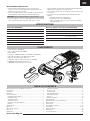
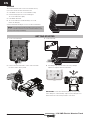
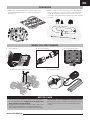
COMPONENTS
• ECX
®
Amp Crush
™
(ECX03048)
• ECX
®
2.4GHz Transmitter (ECX10003)
• AA (4) Batteries
• Speedpack
®
1800mAh Ni-MH 6-Cell Flat w/EC3™ (DYN1050EC)
• ECX
®
ESC/RX 2.4GHz V4 1:10, WP/LiPo (ECX13010)
• Dynamite
®
20T Brushed Motor (DYN1171)
• Spektrum™ 3KG, Plastic Gear Servo, WP, 23T (SPMS603)
• 200mA Wall Charger with EC3 Connector: US
• 200mA Wall Charger with EC3 Connector: INTL

4
EN
1/10 2WD Electric Monster Truck
EN
QUICK START
Please read the entire manual to gain a full understanding of the vehicle, fi ne-tuning the setup and performing maintenance.
1. Read the safety precautions found in this manual.
2. Charge a battery for the vehicle. Refer to the included charging
warnings and instructions for battery charging information.
3. Install the AA batteries in the transmitter. Only use alkaline or
rechargeable batteries.
4. Install the fully charged battery in the vehicle.
5. Power ON the transmitter and then the vehicle. Wait 5 seconds for the
ESC to initialize. Always power the transmitter ON before the vehicle and
power it OFF after the vehicle has been powered OFF.
6. Check the steering and throttle control directions. Verify that the servos
are moving in the correct direction.
7. Drive your vehicle.
8. Perform any necessary maintenance.
VEHICLE PREPARATIONS
CHARGING THE VEHICLE BATTERY
NOTICE: Never charge a battery in the vehicle or damage may result.
1. Connect the NiMH battery to the battery charger.
2. Connect the charger to an AC power outlet.
3. Allow the NiMH battery to charge for 9 hours.
CHARGING WARNINGS
WARNING: Failure to exercise caution while using this product and
comply with the following warnings could result in product malfunction,
electrical issues, excessive heat, FIRE, and ultimately injury and property
damage.
• NEVER LEAVE CHARGING BATTERIES UNATTENDED.
• NEVER CHARGE BATTERIES OVERNIGHT.
• Read all safety precautions and literature prior to use of this product.
• Never leave the battery and charger unattended during use.
• Never allow children under 14 years of age to charge battery packs.
• Never attempt to charge dead or damaged batteries.
• Never charge a battery if the cable has been pinched or shorted.
• Never allow batteries or charger to come into contact with moisture at any time.
• Never charge batteries in extremely hot or cold places (recommended
between 50–80°F [10–26°C]) or place in direct sunlight.
• Always use only Ni-MH rechargeable batteries. This charger cannot charge
batteries such as “heavy duty,” “alkaline,” “mercury” or “lithium” battery.
• Always connect to the charger correctly.
• Always disconnect the battery and charger after charging and let them cool
between charges.
• Always inspect the battery before charging.
• Always terminate all processes and contact Horizon Hobby if the product
malfunctions.
• Always make sure you know the specifications of the battery to be charged
or discharged to ensure it meets the requirements of this charger.
• Always constantly monitor the temperature of the battery pack while charging.
• Always end the charging process if the charger or battery becomes hot to
the touch or starts to change form during the charge process.
• Always charge in a well ventilated area.
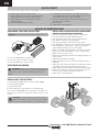
INSTALLING THE BATTERY
1. Turn the battery clips (A) clockwise to remove the battery strap (B).
2. Install a fully charged battery.
3. Install the battery strap.
4. Turn the battery clips counterclockwise to secure the battery strap.
Place foam blocks (ECX236005) in front of the battery so the weight of the
battery increases rear traction or in back of the battery to increase steering
response.
CAUTION: Connecting the battery to the ESC with reversed po-
larity will cause damage to the ESC, the battery or both. Damage
caused by incorrectly connecting the battery is not covered under warranty.
B
A

5
EN
Instruction Manual
TRANSMITTER CONTROLS
STEERING WHEEL
Control steering.
Right and Left
steering
THROTTLE TRIGGER
Controls power
to the motor
for forward
or reverse
Stop
Reverse
Forward
Adjusts the neutral point of the
electronic speed control
THROTTLE TRIM
Adjust to make the vehicle drive
straight with no input at the
steering wheel
STEERING TRIM
POWER SWITCH
Power on or off the transmitter
REVERSE SWITCH
Allows you to change the direction of
steering (ST. REV) and throttle (TH. REV)
controls (Ensure proper function with a
radio system test).
Adjusts the maximum
amount of throttle the
vehicle can be given
THROTTLE DUAL RATE
Adjusts the total steering
travel
STEERING DUAL RATE
INSTALLING THE TRANSMITTER BATTERIES
This transmitter requires 4 AA batteries.
1. Remove the battery cover from the transmitter.
2. Install the batteries as shown.
3. Install the battery cover.
CAUTION: If using rechargeable batteries, charge only rechargeable batteries. Charging
non-rechargeable batteries may cause the batteries to burst, resulting in injury to persons
and/or damage to property.
CAUTION: Risk of explosion if battery is replaced by an incorrect type. Dispose of used
batteries according to national regulations.
BATTERY LEVEL INDICATOR
Solid Red: Battery voltage is good
(above 4V).
Blinking Red: Battery voltage is
critically low (below 4V). Replace
transmitter batteries.

6
EN
1/10 2WD Electric Monster Truck
1. Power on the transmitter.
3. Perform a test of the transmitter’s control of the vehicle with
the vehicle’s wheels off the ground.
4. Start driving slowly, and, if the vehicle does not go straight,
adjust the steering trim dial on the transmitter.
IMPORTANT: Seat the motor brushes by driving smoothly on a fl at
surface during use of the fi rst battery charge. Properly seating the motor
brushes will increase the life and performance of the motor.
2. Power on the ESC.
BINDING
The included transmitter and receiver are bound at the factory.
If you need to rebind, follow the instructions below.
1. Power ON the receiver. The receiver LED fl ashes slowly.
2. Insert the bind plug into the receiver’s binding pins.
The receiver LED flashes rapidly.
3. Power ON the transmitter.
4. The receiver LED turns solid when binding is successful.
Remove the bind plug.
You must rebind when binding the receiver to a different transmitter.
NOTICE: Do not attempt to bind the transmitter and receiver if there
are other compatible transmitters in bind mode within 400 feet. Doing
so may result in unexpected binding.
GETTING STARTED

7
EN
Instruction Manual
• Seat the motor brushes by driving smoothly on a flat surface during
use of the first battery charge. Failing to do so can greatly reduce
motor performance and functional life.
• Prolong motor life by preventing overheating conditions. Undue motor
wear results from frequent turns, stops and starts, pushing objects,
driving in deep water and tall grass, and driving continuously up hill.
Allow the motor to cool completely before running the vehicle.
• Over-temperature protection is installed on the ESC to prevent circuit
damage, but cannot protect the motor from driving against heavy
resistance.
• ALWAYS turn on your transmitter before you turn on the receiver
in the vehicle. Always power off the receiver before turning your
transmitter off.
• ALWAYS operate your vehicle in a wide open area. Operating the
vehicle in a small space or indoors can cause overheating at low
speeds. Operating at low speed increases heat in the electronic
speed control (ESC). Overheating can damage the vehicle and failure
may result.
OPERATION
WHEN YOU ARE FINISHED
MOTOR CARE
1. Power off the ESC. 2. Disconnect the battery.
4. Remove the battery from the vehicle.
3. Power off the transmitter.
5. Recharge the battery.

8
EN
1/10 2WD Electric Monster Truck
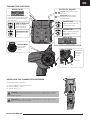
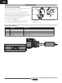
ELECTRICAL LAYOUT
MAINTENANCE
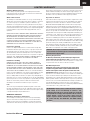
SETTING THE GEAR MESH
The gear mesh has already been set at the factory. Setting the gear mesh
is only necessary when changing motors or gears.
You must remove the vehicle’s gear cover (A) to make this adjustment.
Proper gear mesh (how the gear teeth meet) is important to the
performance of the vehicle. When the gear mesh is too loose, the spur gear
could be damaged by the pinion gear of the motor. If the mesh is too tight,
speed could be limited and the motor and ESC will overheat.
Set the gear mesh by following these simple steps:
1. Loosen the 2 motor screws (B).
2. Put a small piece of paper (C) between the pinion and spur gears.
3. Push the gears together while tightening the motor screws.
4. Rotate the gears to remove the paper. The gearing should move a
small amount.
5. Reinstall the gear cover.
A
C
B
EC3EC3
A
B
C
D
Number Description
A DYN1171
Dynamite 20T Brushed Motor
B
DYNC1050EC Dynamite Speedpack 1800mAh Ni-MH 6 Cell with EC3™
C SPMS603*
Waterproof Steering Servo
D ECX13010
ESC/RX 2.4GHz V4
*OEM part only. Replacement, please use SPMSS6170.

9
EN
Instruction Manual
SHOCK CLEANING
Oil-fi lled shocks require regular maintenance because the oil breaks down
or gets dirty. Perform this maintenance after every 3–5 hours of use,
depending on the conditions.
• Remove the shock from the vehicle.
• Remove the cap from the shock body and dispose of fluid.
• Disassemble the shock. Clean thoroughly with a plastic- and electronic-
safe degreaser (DYNE50001). Dry parts before assembly.
• Re-assemble the shock and refill the shock body with silicone fluid (30
weight recommended).
• Slowly move the shaft and piston up and down to remove air bubbles.
• Move the piston to the midway point of the body and install the cap.
• Wipe off any overflowing fluid.
• When properly filled, the piston should rebound about 3/8 in (9.5mm)
after being pushed in fully.
• Re-install the shock on the vehicle.
Part # Description Part # Description
ECX1036 Shock Body Set ECX1040 Rear Shock Shaft (2)
ECX1037 Shock Caps, Pistons ECX1041 Front Shock Springs (2)
ECX1038 Shock Parts Set ECX1042 Rear Shock Springs (2)
ECX1039 Front Shock Shaft (2) ECX1043 Shock O-Ring Set
No. Description
Tapping
Binder Head
M3x10 mm
Tapping
Binder Head
M3x12 mm
Tapping
Flat Head
M3x15 mm
Tapping
Flat Head
M3x12 mm
Tapping
Flat Head
M3x10 mm
Tapping
Binder Head
M3x18 mm
Tapping Flat Head
M2x16mm
Tapping
Binder Head
M3x16 mm
No. Description
Washer
5x7x0.5 mm
E-Clip E2.5
Lock Washer
Flanged
Lock Nut
M4
Washer
3x8x0.5 mm
Lock Nut
M3
Washer
2x7x0.5 mm
Set Shaft Screw
M3x13 mm
No. Description
Button Hex
M2.5x4mm
Set Screw
M3x3 mm
Set Screw
M3x12 mm
Step Screw
M3x0.5x13.4 mm
Step Screw
M3x0.5x10.5 mm
Button Hex
M2.5x8mm
Step Screw
M3x0.5x7.4 mm
No. Description
Binder Head
M3x8mm
Binder Head
M3x12mm
Binder Head
M3x20mm
Binder Head
M3x25mm
FASTENERS
ECX1043
ECX1037
ECX1041
ECX1037
ECX1043
ECX1036
ECX1038
ECX1038
ECX1043
ECX1037
ECX1037
ECX1038
ECX1037
ECX1042
ECX1040
ECX1057
ECX1037
ECX1043
ECX1038
ECX1039
ECX1036
ECX1038
ECX1038
ECX1037
ECX1057
REAR FRONT
SHOCK ABSORBER PARTS
RIDE HEIGHT ADJUSTMENT
Ride height is an adjustment that affects the way the vehicle jumps, turns
and goes over bumps. Drop one end of the vehicle from approximately 6
inches (152 mm) in height onto a fl at surface. After the vehicle settles, verify
the front arms are equal and parallel to the fl at surface. Do the same with
the rear to make sure both arms are parallel with the fl at surface.
Lowering the front ride height increases steering, but decreases traction.
Lowering the rear ride height increases traction, but decreases steering.

10
EN
1/10 2WD Electric Monster Truck
Problem Possible Cause Solution
Short run time
Battery damaged/not charged Check/change battery
Motor dirty Check/clean
Sluggish action
Motor dirty Check/clean
Bind in drivetrain Clean/adjust
Vehicle battery is not charged Replace/recharge
Controls reversed ST. REV or TH. REV Change switch position
Motor/ESC overheat Over-geared for the driving environment Install smaller pinion on the motor
Does not operate
Transmitter batteries low Replace/recharge
Transmitter powered off Power on
ESC powered off Power on
Vehicle battery is not charged Replace/recharge
Dual-rate (D/R) steering and/or throttle knobs on
transmitter are turned counterclockwise
Adjust dual-rate (D/R) steering or throttle knobs clockwise
to desired setting
Poor range
Transmitter batteries low Replace/recharge
Receiver antenna damaged Check/repair/replace
The system will not connect
Transmitter and receiver too near each other Move transmitter 3.3–9.8ft (1–3m) from receiver
Transmitter and receiver too near large metal
objects (vehicles, etc.)
Move away from large metal objects (vehicles, etc.)
Throttle trim out of center on transmitter
Set throttle trim on transmitter to zero. Turn off and on
transmitter and vehicle
Receiver accidentally put in bind mode so receiver
is no longer bound
Rebind transmitter and receiver
The receiver goes into failsafe
mode a short distance away from
the transmitter
Check the receiver antenna to be sure it is not cut
or damaged
Make sure the antenna is in the antenna tube Contact
Horizon Product Support
The receiver quits responding
during operation
Low battery voltage Completely recharge battery
Loose or damaged wires or connectors between
battery and receiver
Do a check of the wires and connection between battery
and receiver. Repair or replace wires and/or connectors
Receiver and transmitter are not
bound
Transmitter accidentally put in bind mode, ending
bind to receiver
Bind transmitter to receiver
Vehicle moves forward or back-
ward without input from user
Throttle trim on transmitter not centered Adjust throttle trim on transmitter to neutral point
Car does not drive straight Steering trim on transmitter not centered
Adjust steering trim on transmitter so the vehicle drives
straight
No steering or lack of steering
Steering dual-rate (D/R) on transmitter not
adjusted correctly
Adjust steering dual-rate (D/R) knob on transmitter
clockwise to desired steering throw
Servo failed Contact Horizon Product Support
No throttle or lack of throttle
Throttle dual-rate (D/R) on transmitter not adjusted
correctly
Adjust throttle dual-rate (D/R) knob on transmitter clockwise
to desired steering throw
ESC failed Contact Horizon Product Support
Motor failed Contact Horizon Product Support
Clicking noise in transmission
area
Dirt or rocks in spur gear Remove gear cover and inspect. If necessary, replace gear
Motor moved away from spur gear Reset gear mesh
TROUBLESHOOTING GUIDE

11
EN
Instruction Manual
LIMITED WARRANTY
What this Warranty Covers
Horizon Hobby, LLC, (Horizon) warrants to the original purchaser that the
product purchased (the “Product”) will be free from defects in materials and
workmanship at the date of purchase.
What is Not Covered
This warranty is not transferable and does not cover (i) cosmetic damage, (ii)
damage due to acts of God, accident, misuse, abuse, negligence, commercial
use, or due to improper use, installation, operation or maintenance, (iii)
modifi cation of or to any part of the Product, (iv) attempted service by anyone
other than a Horizon Hobby authorized service center, (v) Product not purchased
from an authorized Horizon dealer, or (vi) Product not compliant with applicable
technical regulations or (vii) use that violates any applicable laws, rules, or
regulations.
OTHER THAN THE EXPRESS WARRANTY ABOVE, HORIZON MAKES NO OTHER
WARRANTY OR REPRESENTATION, AND HEREBY DISCLAIMS ANY AND ALL
IMPLIED WARRANTIES, INCLUDING, WITHOUT LIMITATION, THE IMPLIED
WARRANTIES OF NON-INFRINGEMENT, MERCHANTABILITY AND FITNESS FOR
A PARTICULAR PURPOSE. THE PURCHASER ACKNOWLEDGES THAT THEY
ALONE HAVE DETERMINED THAT THE PRODUCT WILL SUITABLY MEET THE
REQUIREMENTS OF THE PURCHASER’S INTENDED USE.
Purchaser’s Remedy
Horizon’s sole obligation and purchaser’s sole and exclusive remedy shall
be that Horizon will, at its option, either (i) service, or (ii) replace, any Product
determined by Horizon to be defective. Horizon reserves the right to inspect
any and all Product(s) involved in a warranty claim. Service or replacement
decisions are at the sole discretion of Horizon. Proof of purchase is required for
all warranty claims. SERVICE OR REPLACEMENT AS PROVIDED UNDER THIS
WARRANTY IS THE PURCHASER’S SOLE AND EXCLUSIVE REMEDY.
Limitation of Liability
HORIZON SHALL NOT BE LIABLE FOR SPECIAL, INDIRECT, INCIDENTAL
OR CONSEQUENTIAL DAMAGES, LOSS OF PROFITS OR PRODUCTION OR
COMMERCIAL LOSS IN ANY WAY, REGARDLESS OF WHETHER SUCH CLAIM IS
BASED IN CONTRACT, WARRANTY, TORT, NEGLIGENCE, STRICT LIABILITY OR
ANY OTHER THEORY OF LIABILITY, EVEN IF HORIZON HAS BEEN ADVISED OF
THE POSSIBILITY OF SUCH DAMAGES. Further, in no event shall the liability of
Horizon exceed the individual price of the Product on which liability is asserted.
As Horizon has no control over use, setup, fi nal assembly, modifi cation or
misuse, no liability shall be assumed nor accepted for any resulting damage or
injury. By the act of use, setup or assembly, the user accepts all resulting liability.
If you as the purchaser or user are not prepared to accept the liability associated
with the use of the Product, purchaser is advised to return the Product
immediately in new and unused condition to the place of purchase.
Law
These terms are governed by Illinois law (without regard to confl ict of law
principals). This warranty gives you specifi c legal rights, and you may also have
other rights which vary from state to state. Horizon reserves the right to change
or modify this warranty at any time without notice.
WARRANTY SERVICES
Questions, Assistance, and Services
Your local hobby store and/or place of purchase cannot provide warranty
support or service. Once assembly, setup or use of the Product has been
started, you must contact your local distributor or Horizon directly. This will
enable Horizon to better answer your questions and service you in the event
that you may need any assistance. For questions or assistance, please visit our
website at www.horizonhobby.com, submit a Product Support Inquiry, or call
the toll free telephone number referenced in the Warranty and Service Contact
Information section to speak with a Product Support representative.
Inspection or Services
If this Product needs to be inspected or serviced and is compliant in the country
you live and use the Product in, please use the Horizon Online Service Request
submission process found on our website or call Horizon to obtain a Return
Merchandise Authorization (RMA) number. Pack the Product securely using a
shipping carton. Please note that original boxes may be included, but are not
designed to withstand the rigors of shipping without additional protection. Ship
via a carrier that provides tracking and insurance for lost or damaged parcels, as
Horizon is not responsible for merchandise until it arrives and is accepted at our
facility. An Online Service Request is available at http://www.horizonhobby.com/
content/service-center_render-service-center. If you do not have internet access,
please contact Horizon Product Support to obtain a RMA number along with
instructions for submitting your product for service. When calling Horizon, you
will be asked to provide your complete name, street address, email address and
phone number where you can be reached during business hours. When sending
product into Horizon, please include your RMA number, a list of the included
items, and a brief summary of the problem. A copy of your original sales receipt
must be included for warranty consideration. Be sure your name, address, and
RMA number are clearly written on the outside of the shipping carton.
NOTICE: Do not ship Li-Po batteries to Horizon. If you have
any issue with a Li-Po battery, please contact the appropriate
Horizon Product Support offi ce.
Warranty Requirements
For Warranty consideration, you must include your original sales
receipt verifying the proof-of-purchase date. Provided warranty conditions
have been met, your Product will be serviced or replaced free of charge. Service
or replacement decisions are at the sole discretion of Horizon.
Non-Warranty Service
Should your service not be covered by warranty, service will be
completed and payment will be required without notifi cation or
estimate of the expense unless the expense exceeds 50% of the
retail purchase cost. By submitting the item for service you are agreeing to
payment of the service without notifi cation. Service estimates are available upon
request. You must include this request with your item submitted for service.
Non-warranty service estimates will be billed a minimum of ½ hour of labor. In
addition you will be billed for return freight. Horizon accepts money orders and
cashier’s checks, as well as Visa, MasterCard, American Express, and Discover
cards. By submitting any item to Horizon for service, you are agreeing to
Horizon’s Terms and Conditions found on our website http://www.horizonhobby.
com/content/service-center_render-service-center.
ATTENTION: Horizon service is limited to Product compliant
in the country of use and ownership. If received, a non-
compliant Product will not be serviced. Further, the sender will
be responsible for arranging return shipment of the un-serviced
Product, through a carrier of the sender’s choice and at the
sender’s expense. Horizon will hold non-compliant Product
for a period of 60 days from notifi cation, after which it will be
discarded.
10/15
ATTENTION: Horizon service is limited to Product compliant
in the country o
f
use and ownership. I
f
received, a non
-
compliant Product will not be serviced. Further, the sender will
be responsible
f
or arranging return shipment o
f
the un-serviced
Product, through a carrier o
f
the sender’s choice and at the
sender’s expense. Horizon will hold non-compliant Product
f
or a period o
f
60 days
f
rom noti
fi
cation, a
f
ter which it will be
discarded
.

12
EN
1/10 2WD Electric Monster Truck
FCC ID: XNZKTH91802G This device complies with part 15 of the FCC
rules. Operation is subject to the following two conditions: (1) This device may
not cause harmful interference, and (2) this device must accept any interfer-
ence received, including interference that may cause undesired operation.
CAUTION: Changes or modifi cations not expressly
approved by the party responsible for compliance could void
the user’s authority to operate the equipment.
This product contains a radio transmitter with wireless technology which has
been tested and found to be compliant with the applicable regulations govern-
ing a radio transmitter in the 2.400GHz to 2.4835GHz frequency range.
FCC INFORMATION
WARRANTY AND SERVICE CONTACT INFORMATION
IC INFORMATION
IC ID: 20264-KTH91802G This device complies with Industry Canada
license-exempt RSS standard(s). Operation is subject to the following two
conditions:
(1) this device may not cause interference, and (2) this device must accept any
interference, including interference that may cause undesired operation of the
device.
ECX AMP Crush | ECX03048I
EU Compliance Statement: Horizon Hobby, LLC
hereby declares that this product is in compliance with
the essential requirements and other relevant provisions of the RED,
EMC, and LVD directives.
A copy of the EU Declaration of Conformity is available online at:
http://www.horizonhobby.com/content/support-render-compliance.
Instructions for disposal of WEEE
by users in the European Union
This product must not be disposed of with other waste.
Instead, it is the user’s responsibility to dispose of their waste
equipment by handing it over to a designated collections point
for the recycling of waste electrical and electronic equipment.
The separate collection and recycling of your waste equipment at the time of
disposal will help to conserve natural resources and ensure that it is recycled
in a manner that protects human health and the environment. For more
information about where you can drop off your waste equipment for recycling,
please contact your local city offi ce, your household waste disposal service or
where you purchased the product.
Country of
Purchase
Horizon Hobby Contact Information Address
United States
of America
Horizon Service Center
(Repairs and Repair Requests)
servicecenter.horizonhobby.com/
RequestForm/
2904 Research Road
Champaign, Illinois, 61822 USA
Horizon Product Support
(Product Technical Assistance)
productsupport@horizonhobby.com
877-504-0233
Sales
websales@horizonhobby.com
800-338-4639
European Union
Horizon Technischer Service service@horizonhobby.eu
Hanskampring 9
D 22885 Barsbüttel, Germany
Sales: Horizon Hobby GmbH +49 (0) 4121 2655 100
C
A
U
TI
O
N: Chan
g
es or modifi cations not expressly
approved by the party responsible
f
or compliance could void
t
h
e user
’
s aut
h
or
i
ty to operate t
h
e equ
i
pment
.

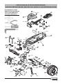
46
PARTS DIAGRAM | EXPLOSIONSZEICHNUNG |
VUE ÉCLATÉE DES PIÈCES | ESPLOSO DEL MODELLO CON REFERENZA PEZZI
1.5 mm
2 mm
RECOMMENDED ITEMS
EMPFOHLENE WERKZEUGE
OUTILS RECOMMANDÉS
ATTREZZI CONSIGLIATI
M3x12
M3x16
M3x16
M3x25
M3x12
M3x10
M3x10
M3x12
M3x25
M3x12
M3x12
M3x10
M3x10
M3x12
M3x12
M3x12
M3x12
M3x10
M3x8
M3x10
M3x12
M3x12
21
23
7
13
14
15
15
23
8
18
8
20
19
16
2
13
20
31
31
7
20
20
1
5
22
44
45
12
17
13
46
19
7
2
8
7
2
19
3
11
11
9
4
49
29
50
52
52

47
PARTS DIAGRAM | EXPLOSIONSZEICHNUNG |
VUE ÉCLATÉE DES PIÈCES | ESPLOSO DEL MODELLO CON REFERENZA PEZZI
The slipper clutch can be adjusted
using this locknut (ECX1060). Fully
tighten the locknut, then loosen the
nut two full turns.
Die Rutschkupplung kann durch
diese Stopmutter eingestellt werden
(ECX1060). Ziehen Sie die Mutter
an und drehen Sie dann volle zwei
Umdrehungen zurück.
Il est possible d’ajuster le
sliper par action sur cet écrou
de blocage (ECX1060). Veillez à
serrer l’écrou de blocage à fond.
Ensuite, devissez l’écrou de
deux tours complets.
La frizione può essere regolata
con questo dado autobloccante
(ECX1060). Prima avvitate comple-
tamente il dado, poi svitatelo 2 giri.
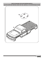
When installing the wheel, make sure the drive hex is aligned with the drive pin.
When the drive hex is removed, the drive pin can fall out of the axle.
Bitte achten Sie bei der Radmontage darauf, dass die Radachse im Radmitnehmer
sitzt und dass der der Querstift nicht heraus fällt.
Lors de l’installation de la roue, assurez-vous que l’hexagone de roue est aligné avec la goupille
d’entraînement. En cas de démontage de l’hexagone, la goupille peut sortir de l’axe et tomber.
Quando montate le ruote, accertatevi che il trascinatore esagonale sia allineato con la spina del
mozzo ruota. Quando togliete il trascinatore esagonale la spina può sfi larsi dal mozzo.
M3x25
M3x12
M3x12
M3x16
M3x18
M3x10
M3x12
M3x12
M3x12
M3x12
M3x12
M3x12
M3x18
M3x10
M3x12
M3x16
M3x3
M2.5x8
M2.5x8
M3x12
M3x12
M3x18
32
32
36 25 3538 33
39 39
22
34
34
34
34 34
15
36
42
15
33
15
48 3548
1515
33
33
33
33
35 33 35 33
36
38
25
M2X16
M2x16
35
12
44
45
25
47
43
43
17
43
11
13
13
47
25
47
3
19
19
29
21
23
13
31
31
15
28
13
20
22
40
29
24
20
20
50
39
6
14
26b
27
26b
27
26a
29

48
PARTS DIAGRAM | EXPLOSIONSZEICHNUNG |
VUE ÉCLATÉE DES PIÈCES | ESPLOSO DEL MODELLO CON REFERENZA PEZZI
51
43

49
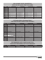
REPLACEMENT PARTS | ERSATZTEILE |
PIÈCES DE RECHANGE | PEZZI DI RICAMBIO
Part # Description Beschreibung Description Descrizione
1
ECX231022 Short Chassis
Chassis Châssis principal Telaio principale
2
ECX1028 Servo Saver Set
Servo Saver Set Sauve servo Set salvaservo
3
ECX2011
Cover and Rear Mount Set Abdeckung und hinterer Halter Set Capot et fi xations arrières Copertura e set di montaggio posteriore
4
ECX1050 Setscrew M3 x 12 (4)
Schrauben Set M3 x 12 (4) Jeu de vis M3 x 12 (4) Grani M3 x 12 (4)
5
ECX236005 Foam Block
Schaum Block Bloc de mousse Spugna distanziale batteria
6 ECX1098
Motor Screw/Washer Set Motor Screw/Washer Set
Set vis/rondelles moteur Viti per il motore/set di rondelle
7
ECX1058 Ball Stud (6)
Kugelkopf (6) Rondelle (6) Sfere uniball (6)
8
ECX1065 Shoulder Screw Set (8)
Passschrauben Set (8) Jeu de vis épaulées (8) Set viti a doppio stadio (8)
9 ECX13010
ESC/RX 2.4GHz V4 ESC/RX 2,4GHz V4 ESC/RX 2,4GHz V4 ESC/RX 2,4GHz V4
11 ECX231024
Battery Strap, ESC Plate Akkugurt, ESC-Platte
Sangle de batterie, plaque du variateur ESC Fascetta batteria, piastra ESC
12 ECX231002
Rear Bumper Set
Hintere Stossstange Pare-choc arrière Set paraurti posteriore
13 ECX2006
Suspension Arm Mount Set Querlenker Set hinten Jeu de renfort de suspension Supporti braccetti sosp.
14
ECX43016
Right/Left, Premount, Wheel (2) Rechts/Links, Premount, Rad (2) Droite/Gauche, Prémontage, Roue (2) Destra/Sinistra, Premount, Ruota (2)
15
ECX1015 Ball Bearing 5 x 10 x 4mm (8) Kugellager 5 x 10 x 4mm (8)
Roulement à billes 5 x 10 x 4mm (8) Cuscinetto a sfera, 5 x 10 x 4 mm (8)
16
ECX1018 Front Suspension Arm Set
Querlenker Set vorne Jeu de bras de suspension avant Braccetti delle sospensioni anteriori
17
ECX1020 Shock Tower Set
Dämpferbrücke Jeu de support d’amortisseur Supporto ammortizzatori posteriori
18
ECX1035 Front Axle (2)
Radachse vorne (2) Axe de roue avant (2) Mozzi ruota anteriori (2)
19
ECX1044 Hinge Pin Set
Querlenkerbolzen Set Jeu d’axes de suspension Set perni sospensioni
20
ECX1046 Camber, Toe Link Set
Spur- Sturzstangenset Jeu de biellettes de carrossage et de pincement Set tiranteria Camber e convergenza
21
ECX1049 Wheel Pins (4)
Radmitnehmerstifte (4) Goupilles d’entraînement (4) Spine trascinatori ruote (4)
22
ECX1060 M4 Locknut (4)
M4 Stopmutter (4) Ecrous auto-freinés M4 (4) Dadi autobloccanti M4 (4)
23 ECX234000
Caster Block, Steer Block, RR Hub (2) Radblock, Steuerblock, Hinterradnabe (2)
Blocs de roulettes, Bloc de direction,
Corps de fusées arrière (2)
Blocco ruota anteriore, blocco sterzo,
mozzo posteriore (2)
24
ECX1019 Rear Suspension Arm Set
Querlenker Set hinten Jeu de bras de suspension arrière Braccetti delle sospensioni posteriori
25
ECX232033 Transmission Case Set
Getriebegehäuse Ensemble carter de transmission Set scatola trasmissione
26a
ECX232000 Long Driveshaft Set, Complete HD (2) Lange Antriebswelle, HD (2) Long arbre de transmission, HD (2) Albero di trasmissione lungo, HD (2)
26b
ECX232002 Long Driveshaft, Plastic Only HD (2)
Lange Antriebswelle, nur Kunststoff
HD (2)
Long arbre de transmission, uniquement
en plastique ultra-résistant (2)
Albero di trasmissione lungo, solo
plastica HD (2)
27
ECX232005 Driveshaft Pivot Ball (4) Antriebswellen Kugelkopf (4) Croisillon de cardan (4) Attacco a sfera semiasse (4)
28 ECX232001
Rear Axle (2) Wellenmitnehmer hinten (2) Axe de roue arriere Attacco a sfera semiasse (4)
29
ECX1045 Button Head Screw 2.5 x 4mm (8)
Rundkopfschraube 2,5 x 4mm (8)
Vis à tête bombée, 2,5 x 4mm (8)
Vite a testa tonda, 2,5 x 4 mm (8)
31
ECX1037
Shock Caps, Pistons, Pivot Ball Set Stoßkappe, Kolben, Schwenkkugel-Set
Ensemble de Capuchons d’amortisseurs,
Pistons, Rotule
Set articolazione a rotula, pistoni,
tappi ammortizzatore
32 ECX231026
Gear Cover Gear Cover Carter de Réducteur Copertura per ingranaggi
33
ECX1022 Transmission Gear Set
Getriebe
Couronne et pignons intermédiaires,
corps et pignons de différentiel
Set ingranaggi trasmissione
34
ECX1024 Slipper Clutch Plates, Pads, Spring
Rutschkupplung Teilesatz Garnitures, plateaux et ressort de slipper Piattelli frizione, disco, molla
35
ECX1025 Transmission Idler Shaft, Drive Pins
Hauptgetriebewelle Set
Arbre secondaire de transmission avec
goupilles d’entraînement
Alberino intermedio con spina
36
ECX1026 Transmission Drive Shaft (2)
Getreibeausgangswelle (2) Axe de sortie de différentiel (2) Mozzi Differenziale (2)
38
ECX1055 Bearings 10 x 15 x 4mm (2)
Lager 10 x 15 x 4 mm (2) Roulements 10 x 15 x 4 mm (2) Cuscinetti 10 x 15 x 4 mm (2)
39
ECX1059 M3 Locknut (4)
M3 Stopmutter (4) Ecrou auto-freiné M3 (4) Dadi autobloccanti M3 (4)
40 ECX232032
Spur Gear 48P, 93T
Hauptzahnrad
48P, 93T
Couronne
48P, 93T
Corona
48P, 93T
42 DYN1171
Dynamite 20T Brushed Motor Dynamite-Bürstenmotor mit 20 Turns Moteur à balais Dynamite 20T Motore con spazzole Dynamite 20T
43 ECX1048
Body Clip (8) Body Clip (8) Clips Carrosserie (8) Clips per carrozzeria (8)
44 ECX231025
Body Post Set
Körperpfosten-Set Set Plots Carrosserie Set di sostegni per la carrozzeria
45 ECX2009
Body Mount Set Aufnahme Karosseriehalter Set Montage Carrosserie Set di montaggio per la carrozzeria
46 ECX2007
Skid Plate Set Skid Plate Set Set Plaque Chassis Set pistre di protezione
47 ECX2013
Rear Bumper Mount Heckstoßstangenhalterung Support de pare-chocs arrière Supporto bumper posteriore
48 ECX1023
Top Shaft/Spacer Top Shaft/Spacer Set de Goupilles Set di spessori
49 ECX1033
Setscrew M3 x 10 Feststellschraube M3 x 10 Vis de fi xation M3 x 10
Vite di arresto M3 x 10
50 ECX231001 Front Bumper Set
Vordere Stossstange Pare-choc avant Set paraurti anteriore
51
ECX230044 Body, Blue
Karosserie, blau Carrosserie, bleue Carrozzeria, blu
51
ECX230045 Body, Orange
Karosserie, orange Carrosserie, orange Carrozzeria, arancione

50
Part # Description Beschreibung Description Descrizione
DYNT0500 Startup Tool Set Anfänger-Werkzeugsatz Jeu d’outils de démarrage Set attrezzi
ECX1061 Screw Set (64) Schraubensatz (64) Jeu de vis (64) Set viti (64)
ECX1095 Aluminum Shock Set, Front Aluminium Stoßdämpfersatz, Vordere Ensemble d’amortisseurs en aluminium, avant Set ammortizzatori anteriori, alluminio
ECX1096 Aluminum Shock Set, Rear Aluminium Stoßdämpfersatz, Heck Ensemble d’amortisseurs en aluminium, arrière Set ammortizzatori posteriori, alluminio
ECX331000 Front Shock Tower, Aluminum Vordere Stoßdämpferbrücke, Aluminium Tour d’amortisseur avant, aluminium Supporto ammortizzatore anteriore, alluminio
ECX331001 Rear Shock Tower, Aluminum Hintere Stoßdämpferbrücke, Aluminium Tour d’amortisseur arrière, aluminium Supporto ammortizzatore posteriore, alluminio
ECX331008 Steering Servo Saver, Aluminum Steuerservo-Saver, Aluminium Économiseur de servo de direction, aluminium Salvaservo sterzo, alluminio
ECX332000 Wheel Hex Set, Aluminum Sechskantradsatz, Aluminium Jeu d’écrous hexagonaux pour roues, aluminium Set trascinatori esagonali, alluminio
ECX334000 Rear Hubs, Aluminum Hintere Nabe, Aluminium Moyeux arrière, aluminium Mozzi posteriori, alluminio
ECX334001 Caster Block, Aluminum Radblock, Aluminium Bloc de rondelle, aluminium Caster block, alluminio
ECX334002 Steering Block, Aluminum Steuerblock, Aluminium Bloc de direction, aluminium Fusello sterzo, alluminio
ECX9001 Metal Gear Set Metallgetriebesatz Ensemble de boîte métallique Set ingranaggi in metallo
RPM70462 Rear A-Arms, Black (2) Hintere A-Arms, schwarz (2) Bras de commande A arrière, noir (2) A-arm posteriori, nero (2)
RPM70582 Front A-Arms, Black (2) Vordere A-Arms, schwarz (2) Bras de commande A avant, noir (2) A-arm anteriori, nero (2)
RPM73292 Front Spindle Blocks, Black (2) Vordere Spindelblöcke, schwarz (2) Bloc d’axe avant, noir (2) Blocchi albero anteriori, nero (2)
RPM73442 HD Caster Blocks, Black HD Radblock, Schwarz Blocs de roulettes ultra-résistants, noirs Caster block HD, nero
RPM73492 SX-Saver Bellcrank, Black SX-Saver-Umlenkhebel, Schwarz Levier coudé SX-Saver, noir Leva a squadra SX-Saver, nero
RPM73572 Rear Axle Carriers, Black Hinterachsträger, Schwarz Supports d’essieu arrière, noirs Porta asse posteriori, nero
Part # Description Beschreibung Description Descrizione
DYN1501 Powerstage Bundle - Stage 1 Leistungsteilpaket – Stufe 1 Lot à étage de puissance, étape 1 Powerstage Bundle-Stage 1
REPLACEMENT PARTS | ERSATZTEILE |
PIÈCES DE RECHANGE | PEZZI DI RICAMBIO
OPTIONAL PARTS | OPTIONALE TEILE |
LISTE DES OPTIONS | ELENCO PARTI OPZIONALI
RECOMMENDED PARTS | EMPFOHLENE TEILE |
PIÈCES RECOMMANDÉES | PARTI RACCOMANDATE
Part # Description Beschreibung Description Descrizione
52 ECX1056 3 × 6 × 2.8mm Bushing (2)
3 x 6 x 2,8 mm Hülse (2) Bague 3 × 6 × 2,8mm (2) Boccola 3 × 6 × 2,8 mm (2)
ECX0945 3 x 25mm Machine Screw (8)
3 x 25 mm Maschinenschraube (8) Vis mécanique 3 x 25 mm (8) Vite a ferro 3 x 25 mm (8)
ECX1051 M3 × 3mm Set Screw (6)
M3 × 3 mm Stellschraube (6) Vis de réglage M3 × 3 mm (6) Vite di fermo M3 × 3 mm (6)
ECX1057 3mm E-Clip (8)
3 mm E-Clip (8) E-Clip 3 mm (8) 3 mm E-Clip (8)
ECX1062 3 × 8mm Button Head Screw (10)
3 × 8 mm Rundkopfschraube (10)
Vis à tête bombée 3 x 8 mm (10)
Vite a testa tonda 3 x 8 mm (10)
ECX1063
3 × 10mm Self-Tap Button Head
Screw (10)
3 × 10 mm selbstschneidende
Rundkopfschraube (10)
Vis à tête bombée auto-taraudeuse
3 x 10 mm (10)
Vite autofi lettante a testa tonda
3 × 10 mm (10)
ECX1064
3 × 12mm Self-Tap Button Head
Screw (10)
3 × 12 mm selbstschneidende
Rundkopfschraube (10)
Vis à tête bombée auto-taraudeuse
3 x 12 mm (10)
Vite autofi lettante a testa tonda
3 × 12 mm (10)
ECX2017
3 × 18mm Self-Tap Button Head
Screw (10)
3 × 18 mm selbstschneidende
Rundkopfschraube (10)
Vis à tête bombée auto-taraudeuse
3 x 18 mm (10)
Vite autofi lettante a testa tonda
3 × 18 mm (10)
ECX2018 3 × 16mm Button Head Screw (10)
3 × 16 mm Rundkopfschraube (10)
Vis à tête bombée 3 x 16 mm (10)
Vite a testa tonda 3 x 16 mm (10)
ECX2019 3 × 10mm Button Head Screw (10)
3 × 10 mm Rundkopfschraube (10)
Vis à tête bombée 3 x 10 mm (10)
Vite a testa tonda 3 x 10 mm (10)

www.ecxrc.com
ECX03048T1/T2
ECX03048IT1/T2
®
© 2019 Horizon Hobby, LLC. ECX, the ECX logo, Amp Crush, Dynamite, Speedpack, Powerstage, EC3 and the Horizon Hobby logo
are trademarks or registered trademarks of Horizon Hobby, LLC. The Spektrum trademark is used with permission of Bachmann
Industries, Inc.
Created 01/2019 58376
-
 1
1
-
 2
2
-
 3
3
-
 4
4
-
 5
5
-
 6
6
-
 7
7
-
 8
8
-
 9
9
-
 10
10
-
 11
11
-
 12
12
-
 13
13
-
 14
14
-
 15
15
-
 16
16
-
 17
17
-
 18
18


ECX ECX03048 Owner's manual
- Category
- Remote controlled toys
- Type
- Owner's manual
Ask a question and I''ll find the answer in the document
Finding information in a document is now easier with AI
Related papers
Other documents
-
 Revolution RVOS02000T1 Owner's manual
-
Axial AXI01002 User manual
-
-
-
-
 Electrix RC Boost ECX3100 User manual
-
 Seymour Duncan PowerStage 170 User guide
-
Vaterra VTR03090 Owner's manual
-
Losi LOS01016T2 Owner's manual
-
 Trek7 rbclo8 User manual


