TEAC Esoteric C-03 Owner's manual
- Category
- Supplementary music equipment
- Type
- Owner's manual

D01022621A
Linestage Amplifier
OWNER’S MANUAL
C-03

2
IMPORTANT SAFETY INSTRUCTIONS
1) Read these instructions.
2) Keep these instructions.
3) Heed all warnings.
4) Follow all instructions.
5) Do not use this apparatus near water.
6) Clean only with dry cloth.
7) Do not block any ventilation openings. Install in accordance
with the manufacturer’s instructions.
8) Do not install near any heat sources such as radiators, heat
registers, stoves, or other apparatus (including amplifiers) that
produce heat.
9) Do not defeat the safety purpose of the polarized or
grounding-type plug. A polarized plug has two blades with
one wider than the other. A grounding type plug has two
blades and a third grounding prong. The wide blade or the
third prong are provided for your safety. If the provided plug
does not fit into your outlet, consult an electrician for
replacement of the obsolete outlet.
10) Protect the power cord from being walked on or pinched
particularly at plugs, convenience receptacles, and the point
where they exit from the apparatus.
11) Only use attachments/accessories specified by the
manufacturer.
12) Use only with the cart, stand, tripod,
bracket, or table specified by the
manufacturer, or sold with the apparatus.
When a cart is used, use caution when
moving the cart/apparatus combination to
avoid injury from tip-over.
13) Unplug this apparatus during lightning storms or when
unused for long periods of time.
14) Refer all servicing to qualified service personnel. Servicing is
required when the apparatus has been damaged in any way,
such as power-supply cord or plug is damaged, liquid has
been spilled or objects have fallen into the apparatus, the
apparatus has been exposed to rain or moisture, does not
operate normally, or has been dropped.
CAUTION: TO REDUCE THE RISK OF ELECTRIC SHOCK,
DO NOT REMOVE COVER (OR BACK). NO USER-
SERVICEABLE PARTS INSIDE. REFER SERVICING TO
QUALIFIED SERVICE PERSONNEL.
The lightning flash with arrowhead symbol, within an
equilateral triangle, is intended to alert the user to the
presence of uninsulated “dangerous voltage” within
the product’s enclosure that may be of sufficient
magnitude to constitute a risk of electric shock to
persons.
The exclamation point within an equilateral triangle is
intended to alert the user to the presence of important
operating and maintenance (servicing) instructions in
the literature accompanying the appliance.

3
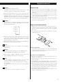
CAUTION Regarding Placement
To maintain proper ventilation, be sure to leave a space
around the unit (from the largest outer dimensions including
projections) equal to, or greater than, shown below.
Left and Right Panels: 20 cm (8”)
Rear Panel: 10 cm (4”)
Top Panel: 5 cm (2”)
CAUTION
< DO NOT REMOVE THE EXTERNAL CASES OR CABINETS TO
EXPOSE THE ELECTRONICS. NO USER SERVICEABLE PARTS
ARE INSIDE!
< IF YOU ARE EXPERIENCING PROBLEMS WITH THIS PRODUCT,
CONTACT TEAC FOR A SERVICE REFERRAL. DO NOT USE THE
PRODUCT UNTIL IT HAS BEEN REPAIRED.
WARNING: TO PREVENT FIRE OR SHOCK
HAZARD, DO NOT EXPOSE THIS APPLIANCE
TO RAIN OR MOISTURE.
This equipment has been tested and found to comply with the
limits for a Class B digital device, pursuant to Part 15 of the
FCC Rules. These limits are designed to provide reasonable
protection against harmful interference in a residential
installation. This equipment generates, uses, and can radiate
radio frequency energy and, if not installed and used in
accordance with the instructions, may cause harmful
interference to radio communications. However, there is no
guarantee that interference will not occur in a particular
installation. If this equipment does cause harmful interference
to radio or television reception, which can be determined by
turning the equipment off and on, the user is encouraged to
try to correct the interference by one or more of the following
measures:
• Reorient or relocate the equipment and/or the receiving
antenna.
• Increase the separation between the equipment and
receiver.
• Connect the equipment into an outlet on a circuit different
from that to which the receiver is connected.
• Consult the dealer or an experienced radio/TV technician
for help.
CAUTION
Changes or modifications to this equipments not expressly
approved by TEAC CORPORATION for compliance will void the
user’s warranty.
For U.S.A.
< Do not expose this apparatus to drips or splashes.
< Do not place any objects filled with liquids, such as vases, on
the apparatus.
< Do not install this apparatus in a confined space such as a
book case or similar unit.
< The apparatus draws nominal non-operating power from the
AC outlet even with its POWER switch turned off.
< The apparatus should be located close enough to the AC
outlet so that you can easily reach the power cord plug at any
time.
< An apparatus with Class
!
construction shall be connected to
an AC outlet with a protective grounding connection.
< Batteries (battery pack or batteries installed) shall not be
exposed to excessive heat such as sunshine, fire or other heat
sources.
< Excessive sound pressure from earphones and headphones
can cause hearing loss.

4
Contents
Thank you for choosing Esoteric. Read this manual
carefully to get the best performance from this unit.
Contents. . . . . . . . . . . . . . . . . . . . . . . . . . . . . . . . . . . . . . . . . . 4
Before use . . . . . . . . . . . . . . . . . . . . . . . . . . . . . . . . . . . . . . . . 5
Identifying the parts . . . . . . . . . . . . . . . . . . . . . . . . . . . . . . . . . 6
Remote control unit . . . . . . . . . . . . . . . . . . . . . . . . . . . . . . . . . 7
Connections . . . . . . . . . . . . . . . . . . . . . . . . . . . . . . . . . . . . . . . 8
Settings 1 . . . . . . . . . . . . . . . . . . . . . . . . . . . . . . . . . . . . . . . . . 9
Settings 2 . . . . . . . . . . . . . . . . . . . . . . . . . . . . . . . . . . . . . . . . 10
Specifications . . . . . . . . . . . . . . . . . . . . . . . . . . . . . . . . . . . . . 12
Troubleshooting . . . . . . . . . . . . . . . . . . . . . . . . . . . . . . . . . . . 12
Block diagram. . . . . . . . . . . . . . . . . . . . . . . . . . . . . . . . . . . . . 13
For European customers
Disposal of your old appliance
1. When this crossed-out wheeled bin symbol is
attached to a product it means the product is
covered by the European Directive
2002/96/EC.
2. All electrical and electronic products should be disposed of
separately from the municipal waste stream via designated
collection facilities appointed by the government or the
local authorities.
3. The correct disposal of your old appliance will help prevent
potential negative consequences for the environment and
human health.
4. For more detailed information about disposal of your old
appliance, please contact your city office, waste disposal
service or the shop where you purchased the product.

5
What’s in the box
Please confirm that the following accessories are in the box
when you open it.
Power cord x 1 Felt pads x 3
Remote control unit (RC-1156) x 1 Owner’s manual x 1
Batteries (AA, R6, SUM-3) x 2 Warranty card x 1
Read this before operation
< Place the unit in a stable location near the stereo system that
you will use.
< Be careful to avoid injury when moving the unit due to its
weight. Get someone to help you if necessary.
< To protect easily scratched furniture, you may stick the felt
pads supplied with the unit to the feet.
< As the unit may become warm during operation, always leave
sufficient space around the unit for ventilation.
The ventilation holes should not be covered. Make sure there
is at least 20 cm (8”) of space above and at least 5 cm (2”) of
space on each side of the unit. Do NOT place anything such
as CD, CD-R, cassette tape etc. on top of the unit.
< The voltage supplied to the unit should match the voltage as
printed on the rear panel. If you are in any doubt regarding
this matter, consult an electrician.
< Choose the installation location of your unit carefully. Avoid
placing it in direct sunlight or close to a source of heat. Also
avoid locations subject to vibrations and excessive dust, heat,
cold or moisture.
< Do not open the cabinet as this might result in damage to the
circuitry or electrical shock. If a foreign object should get into
the unit, contact your dealer or service company.
< When removing the power plug from the wall outlet, always
pull directly on the plug, never yank the cord.
< Do not attempt to clean the unit with chemical solvents as
this might damage the finish. Use a clean, dry cloth.
< Keep this manual in a safe place for future reference.
Maintenance
If the surface of the unit gets dirty, wipe with a soft cloth or
use diluted neutral cleaning liquid. Be sure to remove any
fluid completely. Do not use thinner, benzine (naphtha) or
alcohol as they may damage the surface of the unit.
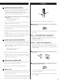
Before use
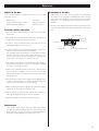
Placement of the unit
High-quality steel is used for the pin-point feet attached to
the bottom of the component. Although the outer feet may
appear loose, the weight of the unit causes them to become
firm and secure. The design effectively damps and reduces
vibration.
< To protect the supporting furniture surface, you may stick the
felt pads supplied with the unit to the bottom of the metal
feet.
Steel foot
Pin-point foot
Bottom plate
of the unit
Cover foot
Cover foot retaining screws

6
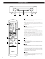
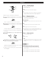
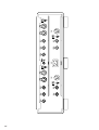
Identifying the parts
F
G
H
I
K
J
L
A C D EB
INPUT
Switches the input source. Select the input terminal for the
equipment that you want to play.
< Allows names of the inputs shown on the display to be
changed and allows inputs to be skipped if they are not being
used (page 11).
POWER
Turns the unit on and off. The indicator next to the button
will light up when the power is on.
< Turns off the power when not using this unit.
< To protect the speakers, first turn the volume of this unit to
minimum, then turn on the power of the source units, next
turn on the power of this unit, finally turn on the power of
the power amplifier that you will use.
To turn off the unit, turn the volume of this unit to minimum,
then turn off the power of the power amplifier, followed by
the power of this unit, finally turning off the power of the
connected sources.
Display
Remote control sensor
Receives signals from the remote control unit. Point the
remote control unit at this sensor when operating the remote
control unit (page 7).
VOLUME
Turn this knob clockwise to increase volume and counter-
clockwise to reduce the volume.
< A sudden loud noise heard over the speakers may damage
your hearing or the speakers. Turn the volume to a minimum
level before you begin playback of the source device. Then
gradually increase the volume as desired.
ON/LIGHT
When this button is pressed, the white button on the remote
control will light up for a few seconds.
Some settings can be changed using this button in “Settings
2” (page 11).
F
E
D
C
B
A

7
VOLUME
Use this button to adjust the volume.
This button also functions as letter selection keys in “Edit
(editable)” setting. See Settings for more information.
< Using the volume buttons on the remote control unit does
not itself change the volume (display), but rather moves the
VOLUME knob on the main unit. In this case, a few seconds
may lapse after the button is pressed before the VOLUME
knob reaches the desired (as shown on the display) position.
DIMMER
Use this button to change the brightness of the front panel
display. Press to select one of four brightness levels for the
display and indicator lamps.
< Note that the OFF setting is not memorized when the power
is turned off. When the unit is turned off with the display
OFF, and then turned on again, the display is reset to the
minimum brightness (FL Dimmer1).
< In OFF mode, when you press a button such as VOLUME, the
illuminations turn on for about 3 seconds.
SETUP
Use this button to enter or exit “Settings 1” and “Settings 2”
(pages 9 to 12).
MUTING
To mute the sound temporarily, press the MUTING button.
Press the MUTING button again to restore the sound.
< While muting is engaged, “MUTING” and the name of the
selected terminal alternately blink on the display.
INPUT
Use this button to change the inputs. Select the input
terminal to which the equipment to play is connected.
This button is also used for selecting settings in “Settings 1”
and “Settings 2”.
This button also functions as cursor keys in “Edit (editable)”
setting.
CLEAR
Use this button to cancel the setting or set-up mode.
L
K
J
I
FL Dimmer3
x
FL Dimmer2
x
FL Dimmer1
x
OFF
H
G
Remote control unit
Notes on use
< Point the remote control unit at the amplifier’s remote sensor
within seven meters (23 feet) of the amplifier. There should
not be any obstacles between the amplifier and the remote
control unit.
< Do not allow direct sun or other light to shine on the remote
sensor on the front of the amplifier. This may cause the
remote control unit to work incorrectly.
< Note that other units with remote controls may operate
incorrectly because of infrared light “overspill” when you
operate this remote control unit.
How to insert the batteries
Remove the cover of the remote control unit with a
screwdriver. After checking the polarity (
+/_) of two AA
batteries, insert the batteries, replace the cover and replace
the screws.
< Be careful not to pinch cables with in the battery case when
reattaching the cover.
Battery replacement
If the distance required between the remote control unit and
main unit decreases, the batteries are exhausted. In this case
replace the batteries with new ones.
Precautions concerning batteries
< Be sure to insert the batteries with correct positive “+” and
negative “
_” polarities.
< Use batteries of the same type. Never use different types of
batteries together.
< Rechargeable or non-rechargeable batteries can be used but
not mixed together. Refer to the precautions on their labels.
< When the remote control unit is not to be used for a long
time (more than a month), remove the batteries from the
remote control unit to prevent them from leaking. If they
leak, wipe away the liquid inside the battery compartment
and replace the batteries with new ones.
< Do not heat or disassemble batteries and never dispose of old
batteries by throwing them in a fire.

8
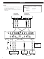
Connections
CAUTION:
< Connect all cables with all units powered off. Be sure to
insert each plug securely. To prevent hum and noise, avoid
bundling the signal interconnection cables together with the
AC power cord or speaker cables.
< Read the instructions of each component you intend to use
with this unit.
RL
IN IN
RL
RL
A
B
C
D
RCA audio cable
RCA audio cable
XLR audio cable
XLR audio cable
Wall socket
Super Audio CD
Player/CD Player etc.
Esoteric uses Esoteric MEXCEL stress-free 7N cable as a
reference. The following items are available in the Esoteric
MEXCEL cable series.
RCA audio cable
XLR audio cable
RCA digital cable
XLR digital cable
BNC digital cable
Speaker cable
Power cable
Super Audio CD
Player/CD Player etc.
LINE OUT
LINE OUT
RCA audio cable
RCA audio cable
XLR audio cable
XLR audio cable
LINE IN LINE IN LINE IN
Power amplifier Right channel Left channel
Power amplifier
XLR pin assignment:
1. COMMON
2. HOT (+)
3. COLD (–)

9
Audio input terminals [LINE IN]
Connect these terminals to CD or Super Audio CD players,
DVD players, cassette tape deck, tuner, DBS receivers, etc.
using commercially available XLR or RCA audio cables.
Connect the unit’s R terminal to the player’s R terminal, and
the unit’s L terminal to the player’s L terminal.
Use commercially available cables for the following
connections.
XLR: balanced XLR audio cable
RCA: RCA audio cable
< The pin assignment of the XLR input terminal can be
changed to #3 HOT (+) (See page 11).
< If you are using balanced connectors, push in the XLR plug
until the lever clicks. To remove the XLR plug, push the lever
and pull out the plug.
< The C-03 does not include a phono equalizer so a turntable
cannot be connected to it unless you use an external phono
pre-amp.
To use a turntable you can run the turntable into a phono
pre-amp and then run from the phono-preamp output into
the C-03 using one of the line level audio inputs.
Audio output terminals [LINE OUT]
Connect these terminals to your power amplifier’s input
terminals using commercially available XLR or RCA audio
cables. Connect the unit’s R terminal to the power
amplifier’s R terminal, and the unit’s L terminal to the power
amplifier’s L terminal.
XLR: balanced XLR audio cable
RCA: RCA audio cable
< The pin assignment of the XLR output terminal is #2 HOT.
< The same signals are output for both 1/2 for the RCA
terminals. Left channel can be connected to 1 and right
channel can be connected to 2.
GND terminal [SIGNAL GND]
Connection of this terminal with the ground terminal of
another unit may improve sound quality.
< Note that this is not an electrical safety ground (earth).
Power cord
Connect the power cord to the power cord receptacle, and
connect the power plug to an AC wall outlet, after all other
connections have been made.
< Use only the supplied power cord. Use of other power cords
may result in fire or electric shock. Unplug the power cord
when you are not going to use the unit for several weeks.
D
C
B
A
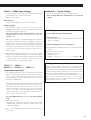
Settings 1
Balance and input level can be adjusted in following steps.
Repeatedly press the SETUP button to select the menu
item to be set.
< If you leave the unit idle for 10 seconds, the setting mode will
be cancelled.
Bal>*** (Left-right balance adjustment)
To adjust the left and right balance of audio outputs.
Settings can be adjusted at 0.5 dB intervals within a range of
L3.0 (dB) to R3.0 (dB).
Default setting is 0.0 (center).
Level>*** (Input level adjustment)
To adjust the level of the selected input. Each input can be
adjusted separately. Settings can be adjusted at 0.5 dB
intervals within a range of –18.0 (dB) to +18.0 (dB). Default
setting is 0.0 (dB).
Use the INPUT buttons (</>) to select options in the
menu item.
To exit the set-up mode, press the SETUP button until
the display returns to normal.
If you leave the unit idle for 10 seconds, the setup mode will
be cancelled automatically.
< Settings are stored even when power is turned off and the
unit is unplugged.
3
2
1
INPUT
SETUP

10
Settings 2
Additional settings are controlled by the following steps.
Press and hold the SETUP button for more than 2
seconds.
“Disp***” appears and the unit enters the setup mode.
Repeatedly press the SETUP button to select the menu
item to be set.
The display changes each time you press the SETUP button.
< If you leave the unit idle for 10 seconds, the setting mode will
be cancelled.
Use the INPUT buttons (</>) to select options in the
menu item.
Repeatedly press the MENU button until the display
returns to normal which exits the setup mode.
If you leave the unit idle for 10 seconds or press the CLEAR
button, the setup mode will be cancelled.
< Settings are stored even when power is turned off and the
unit is unplugged.
4
3
2
1
INPUT
CLEAR
SETUP
ON
Disp>*** (Volume display)
To select the volume display mode.
Default setting is Step.
Step
Adjustment steps from 0 to 99 are displayed.
dB
The attenuation value from the maximum level allowed is
displayed (–90.0 to 0.0). No sound (-∞ dB) is displayed as ---.
Out>*** (Output selection)
To select which terminals outputs sound signals.
Default setting is BOTH (RCA+XLR).
BOTH (RCA+XLR)
Sound signals output from both the RCA and the XLR
terminals.
RCA
Sound signals output from the RCA1 and RCA2 terminals.
XLR
Sound signals output from the XLR terminals.
< If you do not use a set of outputs indicated above, it is
suggested that you turn off those output connectors to enjoy
an incremental improvement in sound quality.
Gain>*** (Gain selection)
To select total gain setting.
0dB
Usual setting.
+12dB
Raises gain by 12dB. Used when you want to listen to sound
loudly or when you want to use the VOLUME knob at lower
positions.
XLR1Hot>***
XLR2Hot>***
(HOT selection for XLR input terminal)
To select #2 HOT or #3 HOT for the XLR input terminal.
Default setting is 2.
2 The pin assignment of the XLR input terminal is #2 HOT.
3 The pin assignment of the XLR input terminal is #3 HOT.

11
RCA3>*** (RCA3 input setting)
To select whether to use the RCA3 input terminal as a normal
input terminal, or as a Signal Thru terminal.
Default setting is NML.
NML (Normal)
Select this to use RCA3 as a normal input terminal.
THRU (Through)
When THRU setting is selected, the volume set by the
VOLUME knob is ignored and the sound signal input into the
RCA3 input terminal is output as it is.
Press the ON button after selecting THRU to enter the
setting.
THRU is displayed instead of the value set by the
VOLUME knob.
When a front speaker is used together with an AV amplifier,
connecting the RCA3 terminal to the FRONT L/R of the AV
amplifier’s pre out terminal and setting RCA3 to THRU will
allow the front speaker to be used as a front speaker for the
AV amplifier when RCA3 is selected. The volume of the front
speaker can then be controlled with the AV amplifier’s
volume control.
< Note: When the RCA3 input terminal is connected to a player
output terminal at THRU setting, there is a risk that a sudden
loud noise can blast over the speakers and may cause damage
to your hearing. Ensure that the pre out terminal is first
connected before selecting setting to THRU.
XLR1=*** XLR2=***
RCA1=*** RCA2=*** RCA3=***
(Input name selection)
The displayed input name can be selected from pre-installed
names or names that you can customize yourself (up to 5
letters) (see “To edit a input name”). Also the input can be
set to skip (Bypass inoperative inputs) when you select sources
by turning the INPUT knob.
For example, when the XLR1 terminal is connected to a super
audio CD player and the RCA1 terminal is connected to a
DVD player, the XLR1 and RCA1 terminals can be set to
“SACD” and “DVD” respectively while the other terminals
can be set to “*skip”. When the INPUT knob is turned, only
“SACD” and “DVD” will be displayed, making it easier to
select only the terminals you want.
Press the INPUT button (< or >) to select the terminal
name.
Default terminal names:
CD, DAC, SACD, DVD, CD-R, DVD-R, TAPE, MD, TUNER,
PHONO, DBS, TVRO, MP3, AUX, TV, VIDEO, VCR, *skip
(SKIP), Edit (editable).
< Note: The skip function will not work when all terminals are
set to “*skip”.
Setup CLR>*** (Erase setting)
To erase all settings and return to the factory default.
After selecting CLR, press the ON button to choose the
setting.
To edit a input name
1 Select “Edit” then press the ON button.
2 Input the letters.
Move the cursor with the </> buttons and select the letters
with the +/– buttons.
3 After finishing input, press the ON button.
< The VOLUME and INPUT knob will not work during this
setting.
< Letters which can be used
Alphabet: A to Z, a to z
Numbers: 0 to 9
Symbols: ! " # $ % & ' ( ) * + , - . / : ; < = > ? @ (blank)
H
Setting and sound quality
Bal (Left-right balance adjustment), Level (Input level
adjustment), Gain (Gain selection) are all selections related to
sound output. These settings and the position of the VOLUME
knob are detected comprehensively by a micro computer and
wholly controlled by a singular volume control amplifier.
It is therefore different from normal amplifiers where sound
signals pass through several circuits. In this design
implementation, there is no deterioration in sound quality
caused by any of these the settings.

12
General
Power supply
Europe model. . . . . . . . . . . . . . . . . . . . . AC 230 V, 50 Hz
U.S.A./Canada model . . . . . . . . . . . . . . . AC 120 V, 60 Hz
Korea model. . . . . . . . . . . . . . . . . . . . . . AC 220 V, 60 Hz
Power consumption . . . . . . . . . . . . . . . . . . . . . . . . . . . 18 W
Weight . . . . . . . . . . . . . . . . . . . . . . . . . . . 22 kg (48 lb 8 oz)
External dimensions (W x H x D)
445 x 129 x 383 mm (17 1/2” x 5 1/16” x 15 1/16”)
Operating temperature . . . . . . . . . . . . . . . . . . . 0˚C to +40˚C
Amplifier Section
Maximum output level. . . . . . . . . . . . . . . . . . . . . . . . . . . 7 V
Output impedance. . . . . . . . . . . . . . . . . . . . . . . 47 kΩ (RCA)
100 kΩ (XLR)
Total harmonic distortion . . . . . . . 0.005% (1 kHz, 2 V input)
0.001% (1 kHz, 2 V input, Awgt)
Frequency response. . . . . . . . . . . . . . . 5 Hz to 120 kHz (–3 dB)
10 Hz to 35 kHz (–0.5 dB)
Signal-to-noise ratio . . . . . . . . . . . . 100 dB (2 V input, Awgt)
Gain . . . . . . . . . . . . . . . . . . 0 dB (default)/+12 dB switchable
Input sensitivity (Gain=0dB mode) . . . . 2.05 V (rated output)
870 mV (850 mV output)
410 mV (400 mV output)
Maximum input level . . . . . . . . . . . . . . . . . . . . . . . . . . . . 7 V
Input impedance . . . . . . . . . . . . . . . . . . . . 40 kΩ (RCA, XLR)
Accessories
Power cord x 1
Remote control unit (RC-1156) x 1
Batteries (AA, R6, SUM-3) x 2
Felt pads x 3
Owner’s manual x 1
Warranty card x 1
• Design and specifications are subject to change without
notice.
• Weight and dimensions are approximate.
• Illustrations may differ slightly from production models.
Troubleshooting
If you experience any problem with this unit, please take the
time to look through this chart and see if you can solve the
problem yourself before calling your dealer.
No power
e Insert the power cord into the AC inlet of this unit.
Remote control does not work.
e Press the POWER switch of the main unit to turn it on (page
6).
e If the batteries are exhausted, change the batteries (page 7).
e Use remote control unit within the range of operation (7
m/23 ft) and point at the front panel (page 7).
Other units with remote controls operate incorrectly.
e Note that other units with remote controls may operate
incorrectly because of infrared light “overspill” when you
operate the remote control unit for the C-03.
There is no sound.
e Adjust the volume.
e Check if the speakers and source components are securely
connected.
e Cancel muting by pressing the MUTING button on the
remote control unit.
e Ensure that the setting is set at output from the terminal
connected in the “Out” mode of Setting 2.
e Check the setting of the connected source components.
VOLUME knob does not work.
e When the input terminal of RCA3 is set to THRU, the
volume control knob will not function during RCA3
inputting.
If normal operation cannot be obtained, unplug the power
cord from the outlet, wait about 60 seconds and plug it
again. This resets the internal circuit which can be
disturbed during electrical storms, power interruptions,
etc. It is strongly suggested that you use power line surge
protection and/or power conditioning systems with this
pre-amplifier.
Specifications
445mm
129mm
383mm

13
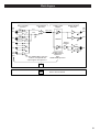
Block diagram
LINE
IN
LINE
OUT
XLR1
HOT
GND
COLD
HOT
8N Cu cable
+
–
+
–
COLD
HOT
GND
COLD
XLR2
RCA1
RCA2
XLR
Lch
Rch
RCA1
RCA2
RCA3/
SIGNAL
THRU
HOT
GND
COLD
Input circuit board
Output circuit board
In the “SIGNAL THRU” mode, the
volume is not adjusted and
output signal is through as it is.
Same as the Left channel
Volume control
Left-Right balance
Input level
Gain
SIGNAL THRU Operation
Balance
amplifier
PGA2320
XLR 1, 2 polarity
inversion
Input amplifier
(Discreet)
Volume control
amplifier
Output amplifier
(Discreet)

14

15

0308
.
MA-1339A
This appliance has a serial number located on the rear panel. Please record
the model number and serial number and retain them for your records.
Model number Serial number
TEAC ESOTERIC COMPANY
1-47 Ochiai, Tama-shi, Tokyo 206-8530, Japan Fax: (042) 356-9240 e-mail: [email protected]
TEAC AMERICA, INC. 7733 Telegraph Road, Montebello, California 90640 Phone: (323) 726-0303 e-mail: [email protected]
TEAC CANADA LTD. 5939 Wallace Street, Mississauga, Ontario L4Z 1Z8, Canada Phone: (905) 890-8008
TEAC MEXICO, S.A. De C.V Campesinos N°184, Colonia Granjas Esmeralda, Delegacion Iztapalapa, CP 09810, México DF Phone: (525) 581-5500
TEAC UK LIMITED Unit 19 & 20, The Courtyards, Hatters Lane, Watford, Hertfordshire, WD18 8TE, U.K. Phone: (0845) 130-2511
TEAC EUROPE GmbH Bahnstrasse 12, 65205 Wiesbaden-Erbenheim, Germany Phone: 0611-71580
-
 1
1
-
 2
2
-
 3
3
-
 4
4
-
 5
5
-
 6
6
-
 7
7
-
 8
8
-
 9
9
-
 10
10
-
 11
11
-
 12
12
-
 13
13
-
 14
14
-
 15
15
-
 16
16


TEAC Esoteric C-03 Owner's manual
- Category
- Supplementary music equipment
- Type
- Owner's manual
Ask a question and I''ll find the answer in the document
Finding information in a document is now easier with AI
Related papers
-
TEAC Esoteric D-07X Owner's manual
-
Esoteric Esoteric D-07X Owner's manual
-
-
-
-
-
-
-
Other documents
-
Esoteric I-03 User manual
-
Esoteric C-02X Owner's manual
-
Esoteric F-05 Owner's manual
-
Esoteric Grandioso F1 Owner's manual
-
Esoteric F-03A Owner's manual
-
Esoteric F-07 Owner's manual
-
Nagra HD PREAMP User manual
-
-
-
Anthem STR Preamplifier User manual