Page is loading ...

Network I/O – SDI
SDI to Routable Audio Network and/or MADI
User Guide
www.solidstatelogic.com
Network I/O SDI. This is SSL.

Page B SDI – User Guide
Dante™ and Audinate™ are registered trademarks of Audinate Pty Ltd
Document History
September 2014 – Initial Release 1.0

SDI – User Guide Page C
Table of Contents
Introduction 1
Introduction 1
Key Features 1
Full Broadcast Specification 1
F
ront Panel Layout 2
Front Panel Indicators 2
Usage Cases 3
Network I/O – SDI to Dante Infrastructure 3
Network I/O – SDI to MADI Infrastructure 3
Hardware Connectivity 4
Power 4
SDI 4
Network (Dante) 4
MADI 4
Sync 4
AES 4
(PHD I/O) 4
Block Diagrams 5
SDI Block Diagram 5
Audio Matrix Diagram 5
Connecting a PC 7
Network 7
IP Address 7
Software Features 9
Loading and Saving Files 9
Routing Files 9
Device Configuration Files 10
Custom Routing 10
Removing Routes 10
Adding Routes 10

Page D SDI – User Guide
Other settings 11
ID 11
Network 11
S
ample Rate 12
Synchronization 12
Word/Video Sync Termination 12
MADI 12
P
HD 13
Dante 13
Optional Module (MADI SFP Fibre) 13
Card Configuration 14
System Delay 14
Alive Time 14
Hardware Configuration 15
Dante Controller Basic Settings 16
Network Config 16
Key things to help you with IP addressing: 16
Appendices 17
Appendix A – Specifications 17
Appendix B – Supported Video Sync Rates 17
Appendix C – Connector Pinouts 18
Appendix D – Safety Notices 19
General Safety 19
Installation Notes 19
Power Safety 19
For EU: 20
Environmental Declaration 20
RoHS notice 20
For USA 20
Electromagnetic Compatibility 20
EMC Performance Criteria 20
Environmental 20
Notes 21

SDI – User Guide Page 1
Introduction
INTRODUCTION
Network I/O – SDI is a broadcast specification bidirectional bridge between Embedded SDI Audio, a Dante IP Audio
Network and industry standard MADI.
Includes eight 3G-SDI paths with embedders and de-embedders for 16 audio channels. The unit has dual Dante and triple
MADI connectivity (2 x optical, 1 x coax). In addition to SDI-Dante bridging, SDI allows direct bridging between SDI and
MADI infrastructure. Internal channel-by-channel routing enables flexible routing between all three domains, or can be
used as a standalone audio router. As you would expect redundant PSUs provide reassurance in a 24-hour Broadcast
environment.
For more information about Dante see Audinate’s website: http://www.audinate.com/
Key Features
• Interface between Embedded SDI audio, Dante and MADI
• Eight 3G-SDI paths with embedders and de-embedders for 16 audio channels
• Redundant: PSU, MADI ports, Dante Ports = Full Broadcast Spec Redundancy
• 2 x SFP optical and 1 x coax MADI I/O
• Internal channel-by-channel routing for all audio paths
• AES Connectivity
• SRC on the Audio path to and from SDI
Full Broadcast Specication
AES11 in
Solid State Logic
Out
In
Out
In
1
2
Out
In
Out
In
1
2
Out
In
Out
In
1
2
Out
In
Out
In
1
2
12345678
WC/VBB
MADI
AES/EBU I/O 1-4
AES/EBU I/O 5-8
out
in
Net 1 Net 2
out
in
Optical I/O
PHD I/O
Primary 1 Pr 2/Exp
100-240 VAC, 50/60 Hz
Max 90 VA
Fuse T1AH/250VAC
AES/EBU Input
/Output
ProTools™
Interface
Two x SFP MADI
Modules
(Option)
MADI
I/O
Redundant
PSU Inputs
Redundant Network
Audio Connections
(Dante)
Wordclock/Video-
reference In/Out
SDI
1&2
SDI
3&4
SDI
5&6
SDI
7&8
DARS
Input

Page 2 SDI – User Guide
F
ront Panel Layout
Front Panel Indicators
RUN Green – Normal operation
PSU Green – Normal operation
STATUS Off – Normal operation
Red – See SDI Manager software for fault details
RUN PSU
STATUS

SDI – User Guide Page 3
NETWORK I/O – SDI TO MADI INFRASTRUCTURE
MADI Console
Dante Console
• Add SDI audio to MADI console
• Add SDI audio to existing Dante infrastructure
Primary Network Switch
Secondary Network Switch
MADI Bridge
8 Inputs
1 to 8
1 to 8
8 Outputs
Dante Intercom
Connection
SDI
MADI Console
Dante wireless Mic
receiver
8 Inputs
Redundant
Fibre MADI
1 to 8
1 to 8
8 Outputs
SDI
Usage Cases
SDI can be used in a variety of scenarios:
NETWORK I/O – SDI TO DANTE INFRASTRUCTURE

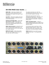
Hardware Connectivity
POWER
Network I/O – SDI includes redundant PSU with IEC connectors, either supply can
individually power the unit – both should be used for redundancy. Ideally these should
be connected to separate mains supplies to provide external connection redundancy.
SDI
8 SDI inputs and 8 SDI outputs with auto format selection up to 3G SDI. These are video
thru circuits with 16 channels of Audio De-Embedding and Embedding. Sample Rate
Conversion (SRC) per audio group. The SDI circuits are represented in the Network I/O –
SDI Software Manager as cards 2, 4, 6 and 8. Each card includes 32 audio channels 1-16
being SDI 1, 17-32 being SDI 2 on each card.
NETWORK (DANTE)
Primary and Secondary Dante connections (Net1 and Net2) are provided on RJ45
connectors. The Primary port is the control connection for the Network I/O SDI
configuration tool.
A pair of LEDs per port provides network connection and activity information:
ACT flashes when there is network activity
GB shows solid green when connected to a gigabit network
Note: The Dante Controller application cannot be used on the secondary connection.
MADI
Three MADI ports can be provided: two fibre and one copper. The optional fibre ports can
be configured to function as a redundant pair. The interface is via SFP sockets, for use
with multimode or singlemode LC fibre cables. The third MADI port is via standard BNC
connectors.
SYNC
Video Sync or Word Clock input on BNC, plus AES11 sync input on XLR are provided. The
unit can also be synchronized from the network (using Dante PTP) any of the MADI
connections or AES inputs. The order of the sync preference can be defined using the
software application.
AES
The AES connection on 25-way D-type connectors allow additional AES connectivity with
Audio routing to any of the other connected devices.
(PHD I/O)
Other/future usage. Not currently implemented.
See Appendix C, page 18 for connector pinout information.
Page 4 SDI – User Guide
AES11 in
S
olid State Logic
Out
In
Out
In
1
2
Out
In
Out
In
1
2
Out
In
Out
In
1
2
Out
In
Out
In
1
2
12345678
WC/VBB
M
ADI
AES/EBU I/O 1-4
AES/EBU I/O 5-8
out
i
n
Net 1 Net 2
out
i
n
Optical I/O
PHD I/O
Primary 1 Pr 2/Exp
1
00-240 VAC, 50/60 Hz
M
ax 90 VA
Fuse T1AH/250VAC
AES11 in
Solid State Logic
Out
In
O
ut
I
n
1
2
Out
In
O
ut
I
n
1
2
Out
In
O
ut
I
n
1
2
Out
In
O
ut
I
n
1
2
12345678
WC/VBB
MADI
AES/EBU I/O 1-4
AES/EBU I/O 5-8
o
ut
in
Net 1 Net 2
o
ut
in
Optical I/O
PHD I/O
Primary 1 Pr 2/Exp
100-240 VAC, 50/60 Hz
Max 90 VA
F
use T1AH/250VAC
AES11 in
Solid State Logic
Out
In
O
ut
In
1
2
Out
In
O
ut
In
1
2
Out
In
O
ut
In
1
2
Out
In
O
ut
In
1
2
12345678
WC/VBB
MADI
AES/EBU I/O 1-4
AES/EBU I/O 5-8
out
in
Net 1 Net 2
out
in
Optical I/O
PHD I/O
Primary 1 Pr 2/Exp
100-240 VAC, 50/60 Hz
Max 90 VA
F
use T1AH/250VAC
AES11 in
Solid State Logic
Out
I
n
O
ut
In
1
2
Out
I
n
O
ut
In
1
2
Out
I
n
O
ut
In
1
2
Out
I
n
O
ut
In
1
2
1
2345678
W
C/VBB
M
ADI
A
ES/EBU I/O 1-4
AES/EBU I/O 5-8
o
ut
in
Net 1 Net 2
o
ut
in
O
ptical I/O
PHD I/O
Primary 1 Pr 2/Exp
1
00-240 VAC, 50/60 Hz
Max 90 VA
Fuse T1AH/250VAC
A
ES11 in
Solid State Logic
Out
In
Out
In
1
2
Out
In
Out
In
1
2
Out
In
Out
In
1
2
Out
In
Out
In
1
2
12345678
WC/VBB
M
ADI
AES/EBU I/O 1-4
AES/EBU I/O 5-8
o
ut
in
Net 1 Net 2
o
ut
in
Optical I/O
PHD I/O
Primary 1 Pr 2/Exp
100-240 VAC, 50/60 Hz
Max 90 VA
Fuse T1AH/250VAC
A
ES11 in
Solid State Logic
Out
In
Out
In
1
2
Out
In
Out
In
1
2
Out
In
Out
In
1
2
Out
In
Out
In
1
2
12345678
WC/VBB
MADI
AES/EBU I/O 1-4
AES/EBU I/O 5-8
out
i
n
Net 1 Net 2
out
i
n
Optical I/O
PHD I/O
Primary 1 Pr 2/Exp
1
00-240 VAC, 50/60 Hz
Max 90 VA
F
use T1AH/250VAC
AES11 in
Solid State Logic
Out
I
n
Out
I
n
1
2
Out
I
n
Out
I
n
1
2
Out
I
n
Out
I
n
1
2
Out
I
n
Out
I
n
1
2
1
2345678
WC/VBB
MADI
AES/EBU I/O 1-4
AES/EBU I/O 5-8
out
in
Net 1 Net 2
out
in
Optical I/O
PHD I/O
Primary 1 Pr 2/Exp
100-240 VAC, 50/60 Hz
Max 90 VA
Fuse T1AH/250VAC
AES11 in
Solid State Logic
Out
In
Out
In
1
2
Out
In
Out
In
1
2
Out
In
Out
In
1
2
Out
In
Out
In
1
2
12345678
WC/VBB
MADI
AES/EBU I/O 1-4
AES/EBU I/O 5-8
out
in
Net 1 Net 2
out
in
Optical I/O
PHD I/O
Primary 1 Pr 2/Exp
100-240 VAC, 50/60 Hz
Max 90 VA
Fuse T1AH/250VAC
AES11 in
Solid State Logic
Out
In
Out
In
1
2
Out
In
Out
In
1
2
Out
In
Out
In
1
2
Out
In
Out
In
1
2
12345678
WC/VBB
MADI
AES/EBU I/O 1-4
AES/EBU I/O 5-8
out
in
Net 1 Net 2
out
in
Optical I/O
PHD I/O
Primary 1 Pr 2/Exp
100-240 VAC, 50/60 Hz
Max 90 VA
Fuse T1AH/250VAC
ACT GB

SDI – User Guide Page 5
Block Diagrams
SDI BLOCK DIAGRAM
AUDIO MATRIX DIAGRAM
Audio Extract
Buffer
Audio
E
mbedder
SRC
SRC
Drop
D
elay
Audio
A
lignment
Buffer
Audio Buffer
Pass
Drop
Use SRC
Insert Sync
Insert Async
Embedder
Enable
Rx SRC enable Gp1 to Gp4
(Setting per group)
4
4
4
Tx Embedder
M
ode Gp1 to Gp4
(Setting per group)
SDI
IN
SDI
OUT
Audio
Router
A
udio In
Audio Out
C
lock
Audio
Extractor
MADI
Dante
2 x Fibre
1 x Coax
8
x
SDI
(3G/HD/SD)
1 x Redundant
connection
AES
8 x channel
pairs
MADI
Dante
2 x Fibre
1 x Coax
8
x
SDI
(3G/HD/SD)
1 x Redundant
connection
AES
8 x channel
pairs
De-Embedder
Embedder
Audio
Router

Page 6 SDI – User Guide
Intentionally blank page

SDI – User Guide Page 7
Connecting a PC
NETWORK
Configuration of the SDI unit is carried out using the ‘SDI Manager’ PC
application. This programme can be downloaded from SSL’s website here.
Connect a Windows™ PC to the Net 1 connector on the SDI unit using a
standard network cable.
IP ADDRESS
SDI units are shipped with a static factory default IP address of
192.168.1.10 for the Network I/O controller.
It is likely that this will need to be changed – or set to automatic – in order
to fit in with the network environment in which the unit is to be installed.
To do this, set your windows PC TCP/IP settings to a fixed address in the
same domain as the SDI unit. (As shown right.)
The SDI Manager connection uses a separate IP address from the
Dante connectivity. Settings for the Dante Environment should
only be managed through the Dante Controller software.
Run the SDI Manager application. If the IP address is correctly
configured the unit will appear in the Device Selection pane of the
software.
To connect to the SDI unit: right-click the IP address and click Connect.
Once connected the unit will be highlighted green.
12345678
Net 1 Net 2
i
n

Page 8 SDI – User Guide
I
P Address
Continued...
H
aving checked you can connect to the device, now close the
c
onnection by right-clicking and selecting Close.
The IP settings cannot be altered whilst the unit is active.
R
ight-click on the target device and select Change Network Settings...
This will allow you to set the SDI unit into DHCP mode or to select a
fixed address to suit your requirements.
Note: Your computer network settings must now be updated to
match those of the SDI unit.

SDI – User Guide Page 9
Software Features
The Network I/O – SDI Manager software window is divided into four panes:
• Device Selection shows available units and their connection status
• Crosspoint Status shows current connections and the buttons for file access
• Crosspoint Control is used to create or remove connections
• Device Status displays hardware information plus some basic interface settings
LOADING AND SAVING FILES
Routing Files
Routing connection files are loaded and saved using the and buttons in the centre pane of SDi
Manager. Routing files are given the extension .xpt (crosspoint).
For the majority of cases Network I/O – SDI will be preconfigured to be used in a specific scenario. SSL provides 3 general
usage-case files that can be loaded onto the SDI unit. These configurations are:
1. 16 channels per SDI to and from the pair of MADI SPFs
2. 8 channels per SDI to and from the first MADI SFP
3. 8 channels per SDI to and from the Dante connection
The files (.xpt) for each of these scenarios can be obtained here:
Crosspoint Files
Note that when loading a crosspoint (.xpt) file, it will ADD the new routes to those already in the
configuration – it does not automatically clear the current routing.

Page 10 SDI – User Guide
D
evice Conguration Files
D
evice configurations can also be stored using the Load and Save buttons in the centre pane – these files are stored as
.
cfg (configuration) files.
For further details, see Other Settings on page 11.
T
he example shown contains three
c
rosspoint routing files and one
device configuration file.
CUSTOM ROUTING
In certain circumstances there may be a requirement to deviate from the default routing in these typical scenarios.
Removing Routes
The centre Crosspoint Status pane of the SDI Manager shows all currently connected
routes.
Select Individual or multiple routes using the left mouse button. Right-click and then
select Disconnect from the option box.
To speed up selection, use the ‘shift’ key and mouse to select a range and use
‘ctrl’ and the mouse to select multiple individual instances.
Adding Routes
The third pane in SDI manager allows any internal routes to be connected. Sources
show in the left column, with destinations in the right. Above each respective
column is a drop down with each physical grouping of IO:
AES 16 channels AES D-sub
PHD Protools HD future usage
MADI MADI Coax connection – up to 64 channels
SFP 1 MADI optical SFP 1 – up to 64 channels
SFP 2 MADI optical SFP 2 – up to 64 channels
IP Dante connection (1-64)
Card 2 (01-16) SDI 1 (1-16)
(17-32) SDI 2 (1-16)
Card 4 (01-16) SDI 3 (1-16)
(17-32) SDI 4 (1-16)
Card 6 (01-16) SDI 5 (1-16)
(17-32) SDI 6 (1-16)
Card 8 (01-16) SDI 7 (1-16)
(17-32) SDI 8 (1-16)
Default view is for .xpt files only. To
see .cfg files, select “All Files”

SDI – User Guide Page 11
Routes are connected by highlighting sources and destinations
in their respective columns and clicking .
T
he selected routes will now be added to the existing routes
s
hown in the crosspoint status window.
can also be used in this pane of the software to
remove routes based on the destination(s) selected.
When stereo signals are available in adjacent odd/even pairs,
these may be routed together by selecting the Stereo button
below the card type selector.
It is possible to perform one-to-many routing (i.e.
distribution) or simultaneous one-to-one routing. If a
differing number of sources or destination is selected then
the number of routes made will be equal to the lower number
of I/O selected in either column.
OTHER SETTINGS
Other settings on specific SDI units are accessed via the button at the lower centre of the left pane in the software
window. Each of the tabs is described in the following section.
Configuration changes can be saved from any of the page tabs.
Note that saving any changes will require a restart of the unit.
ID
➭ Name – A text field available for naming individual units. The name will be
displayed in the Device Selection pane of SDI Manager.
➭ ID can be set for user identification of units which have the same name.
Network
A repeat of the information shown in the “Change Network Settings...” pop-up
but including the MAC address.
Individual (Mono) Route Selection
Stereo Route Selection

Page 12 SDI – User Guide
S
ample Rate
➭ General Sample Rate – Set the general sample rate for the SDI unit to match
t
he wider environment.
➭ Sample Rate Adaptation Source allows the unit’s sample rate to be
automatically adjusted as an external device changes.
The adaption source can be set to any of the separate or embedded clock
reference signals.
➭ Word Clock Output Sample Rate – Used to set the word clock to 48kHz or
44.1kHz (for use if the general sample rate is a higher rate e.g. 96kHz –
sometimes called legacy mode).
Synchronization
Set the hierarchy of clock sources. Double-click in the Priority cell to alter the
settings.
Word/Video Sync Termination
Select the sync termination box to add 75Ω terminator to the sync input BNC.
MADI
Note that these settings apply to the BNC MADI signal only. The optional SFP fibre MADI ports are configured from the
Optional Module tab.
➭ Input Sample Rate can be determined automatically from the incoming
signal or locked to the internal clock.
➭ Output Frame Rate sets the frame rate of the MADI signal (for use at 96kHz):
• High – 96kHz framing pattern
• Legacy – 48kHz framing pattern
➭ Output Channel Status controls user-bit data handling:
• Transparent – Provides pass-through of user bits
• Default – Removes user bits
➭ Output Channel Count – Select 56- or 64-channels

SDI – User Guide Page 13
P
HD
For future use.
Dante
It is recommended that these settings are managed using the Dante controller application only and not via SDI Manager.
The information relating to the interface is included for clarity. See page16 for information relating to Dante Controller.
Optional Module (MADI SFP Fibre)
Each of the SFP fibre MADI interfaces, SFP 1 and SFP 2, has its own settings pane.
➭ Interface Type should be set to Madi – hotlink is not supported.
➭ Input Sample Rate can be determined automatically from the incoming
signal or locked to the internal clock.
➭ Output Frame Rate sets the frame rate of the MADI signal (for use at 96kHz):
• High – 96kHz framing pattern
• Legacy – 48kHz framing pattern
➭ Output Channel Status controls user-bit data handling:
• Transparent – Provides pass-through of user bits
• Default – Removes user bits
➭ Output Channel Count – Select 56- or 64-channels.

Page 14 SDI – User Guide
C
ard Conguration
T
his settings tab provides the configuration control for each of the four, 2-channel SDI interface cards.
The left window is used to select the interface pairs and changes are made in the Value column of the right window.
Double-click in the appropriate field to alter settings.
➭ Embedder – Each channel can be enabled or disabled.
➭ TX Sample Rate can be set to 48kHz, 44.1kHz or 32kHz.
➭ Tx Embedder Mode Group 1–4 controls the signal parameters for each group
through the card:
• Remove – Drops the audio completely
• Pass – Disables the embedder for that group
• Insert Sync – Use when Audio and Video references are synchronous
• Insert Async – Use when Audio and Video references have the same
sample rate but are asynchronous
• Use SRC – Transmitter SRC can be enabled or disabled for each of the
audio groups
➭ Rx SRC Group 1–4 – Receive Sample rate conversion can be enabled or
disabled for each of the audio groups.
System Delay
Not currently implemented.
Alive Time
Not currently implemented.

SDI – User Guide Page 15
H
ardware Conguration
This tab provides rack hardware and software version details. It is for information only and no settings are available.

Page 16 SDI – User Guide
Dante Controller Basic Settings
When using SDI with a Dante network all the Dante and other network settings should be set from Audinate’s Dante
Controller software (downloadable for OSX and Windows here: Dante Controller). Detailed instruction for this software
can be found in the Dante Controller Manual – this guide gives you some basics that will allow you to get started.
R
egistration with Audinate is necessary before files become available for download.
NETWORK CONFIG
Each Dante device requires an IP address for communication – both the Primary and Secondary Network ports can be set
to either DHCP or Fixed Addresses. The Primary and Secondary ports must be kept on separate networks or VLANS. This
document covers the basics of connecting MADI Bridge to a pair of simple networks.
Please consult a network specialist for network design when considering more complex networks.
Key things to help you with IP addressing:
If either (or both) networks does not have a DHCP server and the Primary or Secondary network ports are set to DHCP then
either (or both) will resolve to a link local address, eg. 169.254.x.x. This will take slightly longer to be functional from a
power-up state but will always work.
If using fixed addressing the primary and secondary ports need to be on different subnets.
/