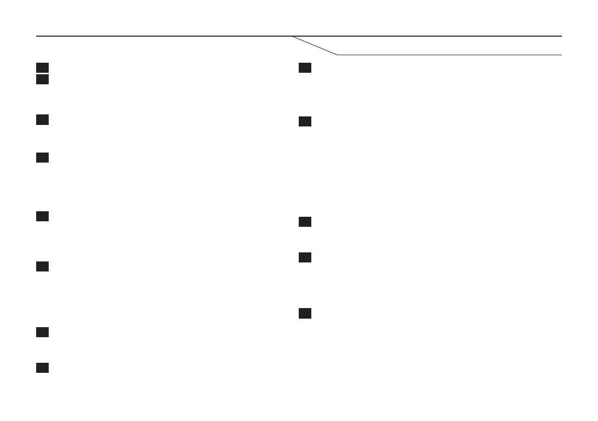
Electrolux CONTROLBOX 24/7 User manual

Type
User manual
2
TABLE OF CONTENTS
Introduction 3
Safety regulations 3
Description 4
Electricity supply 6
Getting started 7
Programming 8
Formatting programming strings 8
Enter reporting number 8
Low temperature warning 9
Entering heat pump model 10
Programmable mode 11
Initiation of remote control IR signal 11
Programming your own IR signals 12
Remote control your heat pump 13
Other settings 14
Temperature compensation 14
Redirecting the confirmation message 15
Check current settings 15
Enter country code 16
Command - list 17
Installation 18
Troubleshooting 19
Key to reports 19
Reset default settings 19
Errors - remedy and cause 20
Specification 21
3
SAFETY REGULATIONS
INTRODUCTION
• Do not let persons, children included, with reduced physical sensory, reduced mental functions or lack of experience and
knowledge use the appliance. They must have supervision or instruction for the operation of the appliance by a person who is
responsible for their safety.
• Do not let children play with the appliance.
Checking a heat pump via texting
A ControlBox24/7 can be used for remote control of a heat pump using text messages. You can combine and choose between
heating, cooling and other temperature settings and fan speeds. ControlBox24/7 also provides the possibility of programming your
own IR signals for other heat pump brands. Simple, selectable commands allow you to quickly change mode and temperature, even
for non-Electrolux heat pumps.
AirCare - Generate complete text messages via an app
If you have a smartphone, you can also use an app which generates a text message for you, and sends it to your ControlBox24/7.
The apps can be downloaded from App Store for iPhone and Google Play for Android under the name 'AirCare'.
Monitoring
ControlBox24/7 also facilitates monitoring temperature and power outages. A text message will be sent to recipients of your choice
if the temperature drops below a set value, or in the event of a power outage.
5
DESCRIPTION
1
7
2
8
5
11
3
9
6
12
13
4
10
IR transmitter
Battery indicator (green)
Temperature sensor
Battery on/off switch
IR transmitter
GSM indicator (red)
GSM test button
SIM card holder
Current indicator (green)
IR receiver
External power supply
IR indicator (orange)
IR test button
Sends IR signals to your heat pump, and has a range of up to
10 metres.
Discreetly placed IR receiver. Reads IR signals through unit
housing, and does NOT need to be exposed by making a hole.
Reads current room temperature. Do not block this hole.
Press the button to read current GSM signal strength. The GSM
indicator will flash from 1 to 10 times, depending on strength
(1 = low signal strength, 10 = high signal strength)
Sends a test signal to your heat pump.
- HL mode: Sends the following setting: "Heat 16°C"
with automatic fan speed".
- HX mode: Sends the following setting: "Heat 18°C"
with automatic fan speed".
- PM mode: Sends the programmed signal in the first slot.
If nothing has been programmed, no signal will
be sent.
Connection for 12V DC, 1A current adapter.
ON: The integrated battery will power the unit in the event
of power loss from the external power connection.
OFF: The unit will not work without an external
power supply being connected
Cover for the SIM card holder and battery switch.
NB! When installing the SIM card, the battery switch must be in the
off position, and the external power supply disconnected.
ON: External power supply connected.
OFF: External power supply disconnected.
ON: Normal battery status.
OFF: Battery disconnected or battery on/off switch is
switched off.
Flashing: Low battery level.
ON: No GSM signal. Seeking GSM signal.
OFF: GSM module has signal and working normally.
Flashing: Error on GSM module, no SIM card.
OFF: Normal setting
Rapid flashing: Sends IR signal via IR transmitter.
Slow flashing: Awaiting incoming IR programming signal
to IR receiver.
Lit for 3 seconds: IR signal programming successful.
6
ELECTRICITY SUPPLY
• The unit is powered by the voltage adapter supplied (230V AC / 12V DC 1A)
• Rechargeable backup battery:
If the unit is deactivated by a power outage, the integrated battery will power it for up to 12 hours. The battery will
be recharged as long as the external power supply is connected. A full battery charge takes approx. 48 hours.
• If the external power supply is disconnected for more than 15 seconds, the power indicator light will go out, and
15 minutes later, a text message stating “AC Power - FAIL, (15 minutes ago)” will be sent.
• When the external power supply is reconnected, the power indicator light will come on, and 15 minutes later, a
text message stating “AC Power - RESTORED, (15 minutes ago)” will be sent.
• If the battery is low, the battery indicator light will start to flash when 20% of battery capacity remains. 3 minutes
after the light starts to flash, the following text message will be sent: “Battery - LOW”.
• When the external power supply has been restored for more than 15 seconds, the battery indicator light will
come on again. The battery will be fully charged again after charging for approx. 48 hours.
7
GETTING STARTED
Fitting the SIM card
Choice of mobile operator
1. Open the SIM card cover on the back of the unit. Set the battery switch
to “OFF” and disconnect the external power supply.
2. Open the slide in which the SIM card will be inserted by carefully pressing
it from the battery switch, raising the slide and inserting the SIM card
with the bevelled corner closest to the battery switch when the slide is
pressed down.
3. Lower the slide and press it carefully sideways towards the battery
switch until you hear a slight “click”.
4. Connect the external power supply and then switch the battery switch to
the “ON” position. Screw the SIM card cover back into place.
When choosing a mobile operator for the SIM card in your ControlBox24/7, always consider the following:
• ControlBox24/7 works best with GSM/2G, which means that operators which only provide 3G WILL NOT
work with the unit.
• Choose the operator with the best GSM cover in the area where you intend to locate your ControlBox24/7.
• If using a prepaid card, remember that most SIM cards will deactivate unless they are regularly topped up.
Check with your mobile operator.
OFF ON
Important!:
For the ControlBox24/7 to work, the PIN code request must
be deactivated on the SIM card before inserting it in the unit!
8
PROGRAMMING
All commands to the unit must be given in capital letters. It is therefore important that you use CAPITALS when sending
commands to the unit. Formulate commands to the unit as follows:
<COMMAND> + <space> + <VALUE>
Examples of all commands are given later in this manual.
The unit will always acknowledge a successful command with “Confirmed: <STATED COMMAND STRING>” so that you know
that the command has been correctly given and executed.
If an incorrect command is sent to the unit, it will automatically forward the message to the primary reporting number
(TEL1) with the following prefix: “Unknown command”.
To enable the unit to know which status reports to send, one or more numbers must be entered. Up to 5 different
numbers can be entered for receiving status reports.
To save a number as the unit's primary reporting number (TEL1) send the following text message to ControlBox24/7;
TEL1 <NUMBER> Example: TEL1 070765874
To enter more report recipients, replace TEL1 with TEL2, TEL3, TEL4 or TEL5.
To delete a registered report number, replace the telephone number with DEL as follows:
TELx DEL Example: TEL2 DEL
The primary reporting number TEL1 differs from the others as follows: if an unknown or
incorrect command is sent to to the unit, it will be automatically forwarded to the number
saved as TEL1.
TIP! If you send TEL? to
ControlBox24/7, you will
receive a list of all telephone
numbers stored in return.
Enter reporting number
Formatting programming strings
9
PROGRAMMING
To see what the current temperature is where your ControlBox24/7 is located, send the following text message to the unit:
TEMP
Request current temperature
LTWARN <NUMBER> Example: LTWARN 12
The example above will cause the unit to send a warning
report when the temperature falls below 12°C, as
“Temperature - LOW”.
If the temperature then increases again and reaches
the set value, another message will be sent saying:
“Temperature - RESTORED”
HTWARN <NUMBER> Example: HTWARN 27
The example above will cause the unit to send a
warning report when the temperature exceeds 27°C as
“Temperature - HIGH”.
If the temperature then decreases again and reaches
the set value, another message will be sent saying:
“Temperature - RESTORED”
The unit’s temperature warning function can be easily
activated or deactivated using the following command:
Activation: LTWON (default setting)
Deactivation: LTWOFF
The unit’s temperate warning function can be easily
activated or deactivated using the following command:
Activation: HTWON
Deactivation: HTWOFF (default setting)
Temperature warning
LOW TEMPERATURE ALARM HIGH TEMPERATURE ALARM
The unit will automatically report if the temperature will exceed the set value. The default setting for low temperature alarm is
+5°C and for high temperature 30°. These values can be changed to between 0°C and +50°C. To change a set value, send the
following text message to the unit:
10
PROGRAMMING
ControlBox24/7 is designed to suit several models of heat pumps, and therefore has to know which model you have. To make this
setting, you need to know which model of heat pump you have. If your heat pump is not an Electrolux model, you can select the
programmable mode, and enter up to 10 different IR signals.
The following 3 modes can be set:
EHEAT - Electrolux Model: Eco Heat. (default setting)
ECOOL - Electrolux Model: Eco Cool.
CHEAT - Electrolux Model: Comfort Heat.
CCOOL - Electrolux Model: Comfort Cool.
HXHEAT - Electrolux older heat pump ranges.
PM - Programmable setting, 10 fixed commands can be entered.
To enter the heat pump to be used, send the following text message to the unit.
TYPE <MODE> Example: TYPE HXHEAT
Once you have made this setting, the unit is ready to be used. See “
Remote control your heat pump
”.
NB! If you have selected the “PM” mode, the IR command has to be programmed in before the unit can control your heat pump.
See “
Programmable mode
Entering heat pump model
11
PROGRAMMING
If you have a non-Electrolux heat pump or other appliance with an IR receiver you want to control, you can use programmable
mode. Up to 10 different fixed IR signals can be programmed in using individual commands.
NB!
To program your own IR signals, the unit must be in programmable mode, see chapter “
Programming - entering heat pump model
for further instructions.
Follow the steps below to program new or replace old IR signals.
Programmable mode
Initiation of remote control IR signal
1. Start by switching off your heat pump, so that the remote control shows that the pump is
switched off.
2. The ControlBox24/7 must first read what type of IR signals your unit uses. Send the
following text message to ControlBox24/7:
RS
3. The unit will go into learning mode, as shown by the IR indicator light flashing slowly for
1 minute, during which you must perform the next step.
4. Aim your remote control at the IR receiver on the right side of the ControlBox24/7 and press the ON/OFF button on your
remote control to start the heat pump.
5. The IR indicator will now indicate that an IR signal is being received by remaining lit for 3 seconds, and will then begin to flash
slowly again. Aim your remote control at the IR receiver on the right side of the ControlBox24/7 again, and press the ON/OFF
button once more.
6. Once the initiation process is completed and successful, the ControlBox24/7 will confirm by sending the following text:
Learning - SUCCESSFUL. NB! The initiation process will not save any IR signal unless it has read which IR format is
to be used.
NB! When the command RS
is sent to ControlBox24/7,
all previously programmed
signals will be deleted.
12
Programming your own IR signals
ControlBox24/7 can store 10 programmed IR signals. You can give each program a name.
Follow the instructions below to program an IR signal in 1 minute.
1. Prepare your remote control so that all the settings you want show on the display, and then switch the remote control off.
2. Send the following text message to the unit:
Rx <COMMAND NAME> Example: R1 Summer
X = program 1-10
You can use upper and lower case letters and numerals in your command name.
(Space or special characters cannot be used)
3. The IR indicator light will start to flash slowly for 1 minute, during which you must aim the control at the IR receiver on the right
side of the ControlBox24/7, and press the ON/OFF button on your remote control.
4. The IR indicator will remain lit for 3 seconds, and the ControlBox24/7 will send one of the following programming confirmations
(see below for explanation):
Learning - SUCCESSFUL - Programming concluded successfully.
Learning - FAILED” - Programming failed. Repeat the process from step 1.
Learning - TIMED OUT” - No IR signal received, or programming took too long. Start again from step 1.
To use the example above, send a text message saying Summer to ControlBox24/7.
NB! For programmed IR signals to work, ControlBox24/7 MUST be in “PM” mode. See
Programming - entering heat pump model”
PROGRAMMING
13
Flexible control (NB: Only works with Electrolux heat pumps)
Once ControlBox24/7 has been set up for the correct heat pump model, you can control your heat pump by sending
text message to the unit. Follow the instructions below for giving the command. Please note that this command will
start the heat pump even when it is switched off.
The modes which can be selected on the heat pump are: HEAT, COOL and DRY.
To send a setting to the pump WITHOUT specifying a fan speed, enter the following:
<MODE><space><TEMPERATURE> Example: HEAT 20
In the example above, the following setting is sent to the heat pump “
Heat, 20°C, automatic fan speed”
An alternative to send to the heat pump is to state a specific fan speed by adding a colon after the temperature, and
then entering the desired fan speed. See the following:
<MODE><space><TEMPERATURE>:<FAN SPEED> Example: COOL 18:2
In the example above, the following setting is sent to the heat pump “
Cool, 20°C, fan speed 2
”.
REMOTE CONTROL YOUR HEAT PUMP
EHEAT ECOOL CHEAT CCOOL HXHEAT
COOL
16-30 16-30 18-32
DRY
16-30 * 16-30 * 16-30 * 16-30 *
HEAT
8, 16-30 8, 16-30 8, 16-30 8, 16-30
Fan speed
0 (auto), 1-5. 0 (auto), 1-5 0 (auto), 1-3. 0 (auto), 1-3. 0 (auto), 1-3.
A list of the available
settings for the various
models is shown on
the right.
*DRY = non-adjustable
fan speed.
TIP! By sending the
OFF command, you can
also switch off the heat
pump.
14
OTHER SETTINGS
Temperature compensation
If your ControlBox24/7 is located where the temperature is consistently a few degrees higher or lower than where you
want to measure it, you can adjust the temperature on the unit.
If you want your ControlBox24/7 to show 2.5 degrees higher than the actual temperature measured, send the
following text message to the unit.
TADJ 025 Where “0” stands for “+”, i.e. the temperature reported will show 2.5°C above the
actual temperature where ControlBox24/7 is located.
If you want to adjust the temperature shown downwards 1.5°, send
TADJ 125 Where “1” stands for “-”, i.e. the temperature reported will show 1.5°C below the
actual temperature where ControlBox24/7 is located.
To deactivate temperature compensation, send:
TADJ 000
To compensate the monitored temperature, send the following text message to your ControlBox24/7:
TADJ <X><YY>
X = 0 for positive value, 1 for negative value.
YY =
05 10 15 20 25 30 35
0.5°C 1.0°C 1.5°C 2.0°C 2.5°C 3.0°C 3.5°C
15
OTHER SETTINGS
Redirecting the confirmation message
Check current settings
By default, your ControlBox24/7 will send all correctly formulated commands back to the same telephone number
they came from.
If your ControlBox24/7 is used by other people, and you want to direct all confirmations of incoming commands to
the unit to a single number, you can designate a standard telephone number as follows:
To check which settings your ControlBox24/7 has at any time, you can request them by entering the following:
SET?
ControlBox24/7 will return all settings made on the unit.
STEL <X> Example: STEL 1
X =
In the example above, all confirmations will be sent to the telephone number saved at TEL1 - See “
Programming - Set
up reporting number
”.
0 1 2 3 4 5
Inactive
TEL1 TEL2 TEL3 TEL4 TEL5
16
Certain mobile operators remove the country code from incoming texts, which can cause a problem if
ControlBox24/7 has to be controlled from a country other than where it is placed. A problem can arise sending back
the confirmation message (only applies if the STEL commando is deactivated). If the problem does occur, you can
use the following command to work around it:
NACO 0&<XXXX> Example: NACO 0&0046
0 = The numbers to be replaced by the country code (usually a zero)
XXXX = Country code where the mobile sending the command is located.
The example above enters the country code when the command text message was sent from Sweden and the
ControlBox24/7 is in another country. I.e.: it is the mobile which sends the text message which determines which
country code will be stated.
To remove the country code setting stated, send the following text message to ControlBox24/7;
NACO &
NB! Only state the country code if you find problems with receiving the confirmation message from
ControlBox24/7.
Enter country code
OTHER SETTINGS
17
Command - list
OTHER SETTINGS
Command Explanation Section reference
HEAT, COOL, DRY Control heat pump setting
Flexible control
HTWARN Sets threshold value for high temperature alarm
Temperature warning
HTWON / HTWOFF Activates/deactivates warning for high temperature
Temperature warning
LTWARN Sets threshold value for temperature monitoring
Temperature warning
LTWON / LTWOFF Activates/deactivates warning for low temperature
Temperature warning
NACO Setting for country code
Enter country code
OFF Switches off heat pump
Flexible control
SET? Returns current settings to ControlBox24/7
Other settings
STEL Sets standard receiver for confirmations
Confirmation message
TADJ Adjusts temperature read
Temperature compensation
TEL? Returns saved reporting phone number
Enter reporting number
TELx Enter phone number for report reception
Enter reporting number
TEMP Returns current temperature
Request current temperature
TYPE Enter which heat pump model is to be controlled
Enter heat pump model
RS Starts initiation phase for learning non-standard IT signals
Initiation of remote control IR signal
Rx Starts learning process for non-standard IR signals
Learn IR signals
18
INSTALLATION
Installation
Location
IR SIGNAL
GSM COVER
ControlBox24/7 has a built-in GSM module which makes it possible to communicate with the unit via text
messages. When deciding where to locate the unit, it is also important that there is sufficient GSM cover.
Hold the unit where you intend to place it and press the GSM test button. The GSM indicator light will flash
1 - 10 times. The higher the number of flashes, the better the GSM cover.
NB! GSM cover must be at least 4 flashes for ControlBox24/7 to work satisfactorily.
ControlBox24/7 has two integrated IR diodes, which send signals via IR light. You must therefore locate the
unit with uninterrupted line of sight to the heat pump to be controlled. Test that the IR signal is received by
pressing the IR test button while holding the ControlBox24/7 where it is to be located, to ensure that the IR
signal is received.
Once you have found the ideal location according to the IR signal's range and GSM signal strength, screw
the mounting plate supplied to the wall using the screws supplied (using plugs if necessary) and hook the
ControlBox24/7 into place. Test the IR and GSM strengths once more using the test buttons, to ensure that
everything is working as it should.
19
Reset default settings
TROUBLESHOOTING
1. Disconnect external power supply and switch off the battery switch under the SIM card cover.
2. Hold down both buttons on the right side of the unit (GSM Test & IR Test buttons) at the same time as you
reconnect the external power supply.
3. When all the lights on the front of the unit flash rapidly, release the buttons on the side.
4. Your ControlBox24/7 is now restored to default settings.
If you want to delete all settings on your ControlBox24/7, the process is simple, using 'default reset'.
Follow the steps below.
Key to reports
Error Text report received Delay before report sent
External power supply error or
disconnected
AC Power - FAIL
(15 minutes ago)
15 minutes
External power supply restored
AC Power - RESTORED
(15 minutes ago)
15 minutes
Battery switched off or disconnected
Battery - DISCONNECTED
3 minutes
Battery reconnected
Battery - CONNECTED
3 minutes
Low battery level
Battery - LOW
3 minutes
Low battery level restored
Battery - Restored
12 hours
High temperature level
Temperature - HIGH (over xC)
3 minutes
Low temperature level
Temperature - LOW (below xC)
3 minutes
Low temperature level restored
Temperature - RESTORED (above xC)
3 minutes
Some reports differ, depending on which version of ControlBox24/7 you have.
20
TROUBLESHOOTING
Causes and solutions
ERROR REMEDY/CAUSE
Unit will not respond to a text message and will
not execute commands despite all indication lights
lighting as they should. (2 green lights)
• Check that the SIM card is active and works using a standard mobile
phone.
Text command executed by ControlBox24/7 but I
receive no text message confirmation
• Check that the SIM card can send a text message from a standard
mobile phone.
• Check that the GSM signal strength is sufficient (Above 4)
• Check that STEL command is set correctly.
• Check country code setting. (NACO)
GSM indicator light on constantly. • The indicator will normally be on for up to 30 seconds during start-up of
ControlBox24/7.
• No/poor GSM signal.
GSM indicator flashing slowly. • Error on SIM card or GSM unit. Test SIM card in standard mobile phone.
Battery indicator light gone out • The backup battery is either switched off or disconnected, check that the
battery switch is in the ON position.
Battery indicator light flashing slowly • The unit has lost external power and the rechargeable backup battery
is running out. Check that the external power supply is working and is
connected.
Power indicator light is off • The unit has lost external power. Check that the adapter is working and is
connected.
21
SPECIFICATIONS
Product specification
Product name ControlBox24/7
Electricity supply 12V DC, 1A (via adapter 230V AC 350mA)
No. of IR transmitters 2
IR transmitter range Up to 10m
No. of IR receivers 1
IR receiver range Up to 30cm
No. of temperature sensors 1
Temperature sensor - range +0°C - +50°C
Backup battery 4.8V, Ni-Mh, 680mAh
Battery time Up to 12h
SIM card holder 1
GSM network GSM 900/1800MHz
Programmable memory slots 10
Ambient temperature -10°C to +50°C (within normal indoor climate conditions)
IP classification IP-20
Weight 235g (incl. wall bracket)
Dimensions 153 x 97 x 33mm (L x W x D) (Incl. wall bracket)
When the product is worn out, do NOT dispose of it with ordinary domestic
refuse. The product must be taken to an electronic recycling station.
Contact your local authority for help if you are unsure about where to hand
in the product.
www.electrolux.com/shop
  • Page 1 1
  • Page 2 2
  • Page 3 3
  • Page 4 4
  • Page 5 5
  • Page 6 6
  • Page 7 7
  • Page 8 8
  • Page 9 9
  • Page 10 10
  • Page 11 11
  • Page 12 12
  • Page 13 13
  • Page 14 14
  • Page 15 15
  • Page 16 16
  • Page 17 17
  • Page 18 18
  • Page 19 19
  • Page 20 20
  • Page 21 21
  • Page 22 22
  • Page 23 23
  • Page 24 24
  • Page 25 25
  • Page 26 26
  • Page 27 27
  • Page 28 28
  • Page 29 29
  • Page 30 30
  • Page 31 31
  • Page 32 32
  • Page 33 33
  • Page 34 34
  • Page 35 35
  • Page 36 36
  • Page 37 37
  • Page 38 38
  • Page 39 39
  • Page 40 40
  • Page 41 41
  • Page 42 42
  • Page 43 43
  • Page 44 44
  • Page 45 45
  • Page 46 46
  • Page 47 47
  • Page 48 48
  • Page 49 49
  • Page 50 50
  • Page 51 51
  • Page 52 52
  • Page 53 53
  • Page 54 54
  • Page 55 55
  • Page 56 56
  • Page 57 57
  • Page 58 58
  • Page 59 59
  • Page 60 60
  • Page 61 61
  • Page 62 62
  • Page 63 63
  • Page 64 64
  • Page 65 65
  • Page 66 66
  • Page 67 67
  • Page 68 68
  • Page 69 69
  • Page 70 70
  • Page 71 71
  • Page 72 72
  • Page 73 73
  • Page 74 74
  • Page 75 75
  • Page 76 76
  • Page 77 77
  • Page 78 78
  • Page 79 79
  • Page 80 80
  • Page 81 81
  • Page 82 82
  • Page 83 83
  • Page 84 84
  • Page 85 85
  • Page 86 86
  • Page 87 87
  • Page 88 88
  • Page 89 89
  • Page 90 90
  • Page 91 91
  • Page 92 92
  • Page 93 93
  • Page 94 94
  • Page 95 95
  • Page 96 96
  • Page 97 97
  • Page 98 98
  • Page 99 99
  • Page 100 100
  • Page 101 101
  • Page 102 102
  • Page 103 103
  • Page 104 104
  • Page 105 105
  • Page 106 106
  • Page 107 107
  • Page 108 108
  • Page 109 109
  • Page 110 110
  • Page 111 111
  • Page 112 112
  • Page 113 113
  • Page 114 114
  • Page 115 115
  • Page 116 116
  • Page 117 117
  • Page 118 118
  • Page 119 119
  • Page 120 120
  • Page 121 121
  • Page 122 122
  • Page 123 123
  • Page 124 124
  • Page 125 125
  • Page 126 126
  • Page 127 127
  • Page 128 128
  • Page 129 129
  • Page 130 130
  • Page 131 131
  • Page 132 132
  • Page 133 133
  • Page 134 134
  • Page 135 135
  • Page 136 136
  • Page 137 137
  • Page 138 138
  • Page 139 139
  • Page 140 140
  • Page 141 141
  • Page 142 142
  • Page 143 143
  • Page 144 144
  • Page 145 145
  • Page 146 146
  • Page 147 147
  • Page 148 148
  • Page 149 149
  • Page 150 150
  • Page 151 151
  • Page 152 152
  • Page 153 153
  • Page 154 154
  • Page 155 155
  • Page 156 156
  • Page 157 157
  • Page 158 158
  • Page 159 159
  • Page 160 160
  • Page 161 161
  • Page 162 162
  • Page 163 163
  • Page 164 164
  • Page 165 165
  • Page 166 166
  • Page 167 167
  • Page 168 168
  • Page 169 169
  • Page 170 170
  • Page 171 171
  • Page 172 172
  • Page 173 173
  • Page 174 174
  • Page 175 175
  • Page 176 176
  • Page 177 177
  • Page 178 178
  • Page 179 179
  • Page 180 180
  • Page 181 181
  • Page 182 182
  • Page 183 183
  • Page 184 184
  • Page 185 185
  • Page 186 186
  • Page 187 187
  • Page 188 188
  • Page 189 189
  • Page 190 190
  • Page 191 191
  • Page 192 192
  • Page 193 193
  • Page 194 194
  • Page 195 195
  • Page 196 196
  • Page 197 197
  • Page 198 198
  • Page 199 199
  • Page 200 200
  • Page 201 201
  • Page 202 202
  • Page 203 203
  • Page 204 204

Electrolux CONTROLBOX 24/7 User manual

Type
User manual

Ask a question and I''ll find the answer in the document

Finding information in a document is now easier with AI