Page is loading ...

Installation, configuration and maintenance
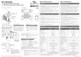
ECOS-D Digital Simulcast Technology
Radio Base Station Guide
A2T NETWORKS

Selex ES S.p.A.
Information contained in this document may not be used, applied or reproduced for any purpose unless agreed
by Selex ES S.p.A. in writing
2
REVISION TABLE
Date
Revision
Comment
06/07/2015
2
Added notes to par. 4
11/06/2015
1
First issue
Information contained in this document may not be used, applied or reproduced for any purpose
unless agreed by Selex ES S.p.A. in writing. Selex ES S.p.A. reserves the right to alter without notice
the specification, design or conditions of supply of any product or service.
Selex ES logo is a trademark of Selex ES S.p.A.
Printed in Italy.
© Selex ES S.p.A. All Rights reserved.

Selex ES S.p.A.
Information contained in this document may not be used, applied or reproduced for any purpose unless agreed
by Selex ES S.p.A. in writing
3
Summary
1. Scope ............................................................................................................................................................... 5
2. First aid for electrical shock and safety rules ................................................................................................ 5
2.1 First aid for electrical shock ................................................................................................................. 5
2.1.1 Artificial respiration ........................................................................................................................ 5
2.1.2 Treatment of burns........................................................................................................................... 5
2.2 Product Safety and RF Exposure Compliance .................................................................................... 7
2.2.1 RF Exposure Compliance ................................................................................................................ 7
2.2.2 Electrostatic protection .................................................................................................................... 7
3. Encoding criteria for all derived Products ..................................................................................................... 8
4. Technical/Environmental Specification ...................................................................................................... 10
5. Device Assembly and composition ............................................................................................................... 12
5.1 Position of the connectors and switches ............................................................................................. 14
5.1.1 Archetype ...................................................................................................................................... 14
6. Installation .................................................................................................................................................... 15
6.1 Overview ............................................................................................................................................... 15
6.1.1 Installation Pre-requisites .............................................................................................................. 15
6.1.2 Unpack ........................................................................................................................................... 16
6.1.3 Mechanical installation .................................................................................................................. 16
6.1.4 Electrical wiring ............................................................................................................................ 18
6.1.5 Unit grounding ............................................................................................................................... 18
6.2 Power supplies interfaces .................................................................................................................... 20
6.2.1 48 Vdc input .................................................................................................................................. 20
6.3 Radio Interfaces ................................................................................................................................... 23
6.3.1 TX N type connector ..................................................................................................................... 23
6.3.2 RX N type connector ..................................................................................................................... 24
6.3.3 Diversity receivers interfaces - Dual BNC type connector ............................................................ 25
6.4 Line interfaces ...................................................................................................................................... 26
6.4.1 4W and 4W+E/M Link .................................................................................................................. 26
6.4.2 E1 coax Link .................................................................................................................................. 33

Selex ES S.p.A.
Information contained in this document may not be used, applied or reproduced for any purpose unless agreed
by Selex ES S.p.A. in writing
4
6.4.3 AF in/out ........................................................................................................................................ 35
6.4.4 LAN Interface ................................................................................................................................ 39
6.4.5 Serial Interface ............................................................................................................................... 41
6.4.6 Auxiliary Serial Interface .............................................................................................................. 43
6.4.7 Digital Input/Output Interface ....................................................................................................... 46
6.4.8 Local Microphone Interface .......................................................................................................... 48
7. Configuration ............................................................................................................................................... 50
8. Maintenance ................................................................................................................................................. 50
8.1 Module features, alarms and troubleshooting................................................................................... 50
8.1.1 CORE module - CORE .................................................................................................................. 50
8.1.2 4 Lines Interface module – LIF ..................................................................................................... 53
8.1.3 Digital Interface module – DIF ...................................................................................................... 54
8.1.4 Double Radio Receiver module – RRX ......................................................................................... 55
8.1.5 Switch module – SWITCH ............................................................................................................ 57
8.1.6 DC/DC module – DC/DC .............................................................................................................. 58
8.1.7 Radio Receiver and Transmitter module – RTX ........................................................................... 58
8.1.8 Power Amplifier module – PA ...................................................................................................... 60
8.2 Power modules maintenance precaution ........................................................................................... 62
8.3 Module removal ................................................................................................................................... 63
8.4 Back card removal ............................................................................................................................... 64
8.5 Local Maintenance Interface .............................................................................................................. 65
8.6 Local Test AF Interface ...................................................................................................................... 67
8.7 Remote Maintenance Interface .......................................................................................................... 69

Selex ES S.p.A.
Information contained in this document may not be used, applied or reproduced for any purpose unless agreed
by Selex ES S.p.A. in writing
5
1. Scope
This manual provides experienced technicians familiar with similar types of equipment with information
which permit the installation and maintenance of the described product, whose characteristics are
described in the Technical specification Section.
This document does not contain information of the maintenance and configuration software that are
provided with the software itself.
Information contained in this document are valid only for the model named ECOSD RBS4000K
U5110DA0C14W0E100S1V1G2, whose certification number is FCC ID: X5YF767DHDE-IP and IC:
12512A-F767DHDEIP, of the ECOS-D family of products, optional cards and ancillaries included. The
technicians must use only the part of information related to the RBS really shipped.
2. First aid for electrical shock and safety rules
2.1 First aid for electrical shock
Do not touch the patient with bare hands until the circuit has been opened. Open the circuit by
switching off the line switches. If that is not possible protect yourself with dry material and free the
patient from the conductor.
2.1.1 Artificial respiration
It is important to start mouth resuscitation at once and to call a doctor immediately. Suggested
procedure for mouth to mouth resuscitation method is described in Table 1.
2.1.2 Treatment of burns
This treatment should be used after the patient has regained consciousness. It can also be employed
while artificial respiration is being applied (in this case there should be at least two persons present).
Warning
• Do not attempt to remove clothing from burnt sections
• Apply dry gauze on the burns
• Do not apply ointments or other oily substances.

Selex ES S.p.A.
Information contained in this document may not be used, applied or reproduced for any purpose unless agreed
by Selex ES S.p.A. in writing
6
Table 1: First aid

Selex ES S.p.A.
Information contained in this document may not be used, applied or reproduced for any purpose unless agreed
by Selex ES S.p.A. in writing
7
2.2 Product Safety and RF Exposure Compliance
2.2.1 RF Exposure Compliance
The described product is intended for use in occupational/controlled conditions, where users have full
knowledge of their exposure and can exercise control over their exposure to meet R&TTE and FCC/IC
limits. This RBS is NOT authorized for any other use.
_________________________________________________________________________
- The minimum safe distance to antenna, depending on antenna gain, is shown in the
following table:
- La distance minimale de sécurité à l'antenne, en fonction de gain de l'antenne elle-même,
est illustré dans le tableau suivant.
Antenna Gain
Gain de l’antenne (dBi)
Safe distance
Distance de sécurité (cm)
8 (typ.)
450
15 (max.)
1000
_________________________________________________________________________
2.2.2 Electrostatic protection
When the equipment units are provided with the plate, shown in Figure 1 it means that they contain
components electrostatic charge sensitive.
Figure 1 Electrostatic sensitive equipment
In order to prevent the units from being damaged while handling, it is advisable to wear an elasticised
band (Figure 2) around the wrist ground connected through coiled cord (Figure 3) to the appropriate
point on the RBS (Figure 4)

Selex ES S.p.A.
Information contained in this document may not be used, applied or reproduced for any purpose unless agreed
by Selex ES S.p.A. in writing
8
Figure 2 Antistatic band
Figure 3 Coiled Cord
Figure 4 Antistatic contact point
3. Encoding criteria for all derived Products
The following table sets out the criteria for coding of products derived from the archetype, and is
specific to an equipment ECOSD A2T-band 896-941 MHz 110W PA.
The model number for each products derived from the archetype, is obtained by assigning to the
variables that make up (highlighted in green), one of the value shown in the table.
Tab. 2
General Code: ECOSD RBS4000K aabbbWAcde4WgE1hmSnVpGr
Frequency Band
aa
aa = U5 (896 - 941 MHz)
aa = 00 - indicates no part radio
RF Power
bbbW
bbb = 110 - Pout 110W
bbb = 000 - indicates no Power Amplifier module
W = W Configuration without RX Diversity
W = D Configuration with RX Diversity
Power Supply
Acde
c = 0 - does not provide 12Vdc power supply
Antistatic
contact point

Selex ES S.p.A.
Information contained in this document may not be used, applied or reproduced for any purpose unless agreed
by Selex ES S.p.A. in writing
9
d = 0 - indicates the absence of alternatives at 12Vdc powr supply
d = C - indicates 48Vdc power supply
e = 1 - indicates one power supply module
e = 0 - indicates no power supply modules
4 Wires interfaces
4Wg
g = 1 - indicates one LIF (Line Interface module) with back-
card
g = 0 indicates no Line Interface modules and no back-card
E1 Interfaces
E1hm
h = C - indicates back-DIF (Digital Interface back-card) with
coax connectors @75 Ohm unbalanced
h = R - indicates back-DIF (Digital Interface back-card) with
RJ45 connectors @120 Ohm balanced
h = 0 - indicates no back-DIF
m = 1 - indicates one Digital Interface module
m = 0 - indicates no Digital Interface modules
Option Board -
SOIP
Sn
n = 1 - indicates one SOIP piggy-back on one CORE module
n = 0 - indicates no SOIP piggy-back
Option Board -
VOCODER
Vp
p = 1 - indicates one VOCODER piggy-back on one CORE
module
p = 0 - indicates no VOCODER piggy-back
Synchronization -
GPS receiver
Gr
r = 1 - indicates one GPS receiver piggy-back on one CORE
module (Master)
r = 2 - indicates two GPS receiver piggy-back on one CORE
module (Master)
r = 0 - indicates no GPS receivers piggy-back

Selex ES S.p.A.
Information contained in this document may not be used, applied or reproduced for any purpose unless agreed
by Selex ES S.p.A. in writing
10
4. Technical/Environmental Specification
The main characteristic of the device are:
Radio Frequency:
Frequency range 896 – 941 MHz (RX: 896 – 912 MHz; TX: 927-941 MHz)
(for Canadian and US market: RX: 896 ÷ 901 MHz
/ TX: 935 ÷ 940 MHz)
Channel Spacing 12,5 – 25 kHz
(for Canadian and US market: 12,5 kHz only / Authorized
bandwidth 13,6 kHz)
Channel step 5 kHz – 6,25 kHz
RF Power 10 – 110 Watt (step 0,1 dB), continuous transmission
Modulation type Dual mode
Analog FM/PM (EN 300 086 – EN 300 113)
11K0F3E/11K0G3E
16K0F3E/16K0G3E (not valid for Canadian
and US market)
Digital 4FSK (TS 102 361-1,2,3)
7K60FXD/7K60FXE
C4FM
8K10F1D/8K10F1E
CTCSS 67 – 254.1 Hz (step 0,1 Hz)
DCS yes
Antenna connector 50 Ohm
Emission mode Duplex/Simplex
Receiver sensitivity Analog FM (12,5 kHz): -112 dBm @ 20 dB SINAD psofo
Digital 4FSK: -118 dBm @ BER = 5x10⁻²
Digital C4FM: -118 dBm @ BER = 5x10⁻²
Power supply:
Input voltage 48 Vdc (35 75 Vdc - galvanically insulated)
Current drain

Selex ES S.p.A.
Information contained in this document may not be used, applied or reproduced for any purpose unless agreed
by Selex ES S.p.A. in writing
11
Stand-by 0,9 A max @ 48 Vdc
Transmit 7,0 A max @ 48 Vdc
NOTE: current drain values are for fully equipped devices.
Environmental condition:
Operating temperature -30 - +60 °C (-22 - +140 °F)
This is the temperature measured in close proximity to the
device. If the device is mounted in a cabinet, the temperature
within the cabinet is measured.
Humidity should not exceed 90% relative humidity @ 50°C (122°F) non
condensating
Air Quality For equipment operating in an environmentally controlled
environment with repeater(s) rack mounted, the airborne
particle level must not exceed 25 μg/m³.
For equipment operating in an area which is not
environmentally controlled (repeater(s) cabinet mounted), air
borne particle level must not exceed 90 μg/m³.
Equipment Ventilation the repeater is equipped with two cooling fans that are used to
provide forced convection cooling. Customer-supplied
cabinets must be equipped with ventilation slots or openings
in the front (for air entry) and back or side panels (for air to
exit). If several repeaters are installed in a single cabinet, be
sure ventilation openings surround each repeater to allow for
adequate cooling. A minimum of ½ RU (4,4 cm – 0,8 inches)
must be left among devices installed in the same cabinet.

Selex ES S.p.A.
Information contained in this document may not be used, applied or reproduced for any purpose unless agreed
by Selex ES S.p.A. in writing
12
5. Device Assembly and composition
Front overview.

Selex ES S.p.A.
Information contained in this document may not be used, applied or reproduced for any purpose unless agreed
by Selex ES S.p.A. in writing
13
Rear overview.

Selex ES S.p.A.
Information contained in this document may not be used, applied or reproduced for any purpose unless agreed
by Selex ES S.p.A. in writing
14
5.1 Position of the connectors and switches
5.1.1 Archetype
Front view:
Rear view:
GPS antenna
AUX Serial port
LAN port
4W(+E/M) local port
Main Serial port
48 Vdc input
RF RX antenna
RF TX antenna
I/O port
RF RX antenna diversity
Loudspeaker
Microphone/AF test
RBS Power on/off switch
Antistatic contact
Main Power on/off switch
I/O port

Selex ES S.p.A.
Information contained in this document may not be used, applied or reproduced for any purpose unless agreed
by Selex ES S.p.A. in writing
15
6. Installation
6.1 Overview
The device can be shipped preinstalled in a cabinet or not. If it is not shipped preinstalled in a cabinet,
after unpacking, mechanical installation takes place, followed by electrical connections as described in
this document. The device may be installed in any location suitable for electronic communications
equipment, provided that the environmental conditions do not exceed the equipment specifications for
temperature, humidity, and air quality and that the access to that location is restricted as described
below:
_________________________________________________________________________
- access can only be gained by service persons or by users who have been instructed about
the reasons for the restrictions applied to the location and about any precautions that be
taken; and
- access is through the use of a tool or lock and key, or other means of security, and is
controlled by the authority responsible for the location
_________________________________________________________________________
6.1.1 Installation Pre-requisites
To ensures the best possible performance and reliability of the described equipment pre-installation
planning is required. This includes considering the mounting location of the repeater in relation to input
power and antennas. Also to be considered are site environment conditions, the particular mounting
method and required tools and equipment.
_________________________________________________________________________
To plan the installation, please pay particular attention to environmental condition at the site;
ventilation requirements, grounding and lightning protection as described in this manual.
_________________________________________________________________________

Selex ES S.p.A.
Information contained in this document may not be used, applied or reproduced for any purpose unless agreed
by Selex ES S.p.A. in writing
16
After that, following the instruction given in this manual:
Unpack and inspect the equipment.
Mechanical install the equipment at the site.
Make necessary electrical wiring:
- Unit Grounding
- DC/DC input cabling
- Coaxial cables to transmit and receive antennas
Perform a post-installation function checkout test of the equipment to verify proper
installation.
Proceed to customize the repeater parameters per customer specifications (e.g.
operating frequency, PL, codes, color code, etc.)
6.1.2 Unpack
Inspect the equipment for damage immediately after unpacking and make a report of the extent of any
damage to the transportation company and to Selex ES S.p.A.
The following items are packed together:
ECOS-D A2T Radio Base Station
DC power cable
This manual
6.1.3 Mechanical installation
The device is shipped in a box. Upon delivery, the equipment must be removed from the container
(see Unpack section) and transferred to a rack or cabinet if not provided.
If the device is supplied without a cabinet it is designed to be fitted in a 19” cabinet using 3 RU of
space.

Selex ES S.p.A.
Information contained in this document may not be used, applied or reproduced for any purpose unless agreed
by Selex ES S.p.A. in writing
17
M6 screws
Customer-supplied cabinets and racks must have mounting rail and hole spacing compatible with EIA
Universal 48.3 cm (19 inches) specifications. Cabinets must provide adequate ventilation and must
meet the following criteria:
45.0 cm (17.71 inches) deep
48.3 cm (19 inches) wide
13.4 x 3 cm (15.75 inches) high
Two mounting rails 5 cm (2 inches) from front cabinet with front mounting holes 5.7 cm (2.25
inches) apart (center to center).
The front of the device is provided with four holes for M6 screws (highlighted above in green) for each
level. This permits to fasten the device to a 19” rack by means of 4 M6 screws for each level.
If several devices are installed in a single cabinet, be sure equipment have to be spaced at least by
1/2 RU (2,2 cm, 0,8 inches).to allow for adequate cooling.
Cabinets must have a least 15 cm (6 inches) of open space between the air vents and any wall or
other cabinets. This allows adequate air flow.
When multiple cabinets (each equipped with several repeaters) are installed in an enclosed
area, ensure appropriate ventilation and consider air conditioning or other climate control
equipment to satisfy the temperature requirements.

Selex ES S.p.A.
Information contained in this document may not be used, applied or reproduced for any purpose unless agreed
by Selex ES S.p.A. in writing
18
6.1.4 Electrical wiring
The electrical wiring must be done using appropriate cables thus assuring the equipment responds to
the electromagnetic compatibility standards.
The cable terminates to flying connectors which have to be connected to the corresponding
connectors on the equipment rear panel.
_________________________________________________________________________
The connector of the power cable supplied with the product is the means to disconnect
the device from the power source.
_________________________________________________________________________
Position and pin–out of the equipment connectors are available in the appropriate section in the
following of this document.
6.1.5 Unit grounding
_________________________________________________________________________
The device is equipped with a protection ground nut located on the lateral side panel of the
device and identified by a label.
_________________________________________________________________________
This nut must be used for a direct connection of the device to the site grounding, even if the device is
included in a cabinet. All antenna cables and DC power cabling should be properly grounded and
lightning protected. Failure to provide proper lightning protection may result in permanent damage to
the radio equipment.

Selex ES S.p.A.
Information contained in this document may not be used, applied or reproduced for any purpose unless agreed
by Selex ES S.p.A. in writing
19
Figure 5 Ground screw
Interconnecting points
Type of connector terminating
the cable
Type of cable/conductor
Ground
M6 nut
Note. Resistance between ground terminal and other metallic parts of the device verified applying
between the two sides a current of 32 A for 4 minutes.
Protection
ground
connection

Selex ES S.p.A.
Information contained in this document may not be used, applied or reproduced for any purpose unless agreed
by Selex ES S.p.A. in writing
20
6.2 Power supplies interfaces
6.2.1 48 Vdc input
Use the connector marked in red to connect RBS to the output of the 48 VDC power supply. Each
level must be connected separately the 48 VDC power supply. The RBS is galvanically insulated..
Interconnecting points
Type of connector terminating
the cable
Type of cable/conductor
Power supply 35 – 75 Vdc
Polarised SUB–D 3W3 female
connector
sq.mm. (for length < 6 m)
D-SUB 3W3 female pinout
PIN
(soldering side view)
A1
Negative voltage
A2
Not used
A3
Positive voltage
Hereafter the power cable supplied with the 48 Vdc powered device is shown. The cable is provided
with D-SUB 3W3 female connector and a 30A fuse.
/