Page is loading ...

<Ersetzen Sie diese Abbildungsfläche
durch Ihre Produktabbildung>
Instruction manual
RE 15215-01-B/11.2015
Replaces: 08.09
English
Radial piston motor
MCR
Series 30, 31, 32, 33 and 41

The data specified below serves to describe
the product. Where information refers to
use this refers to an example application
only. Information from the catalog are not
guaranteed properties. The information given
does not absolve the user from the obligation
of own judgment and verification. Our products
are subject to a natural wear and aging
process.
© This document, as well as the data,
specifications and other information set forth in
it, are the exclusive property of Bosch Rexroth
AG. It may not be reproduced or given to third
parties without its consent.
The cover shows an example application. The
product delivered may differ from the image on
the cover.
The original instruction manual was created in
the English language.

RE 15215-01-B/11.2015, MCR Series 30, 31, 32, 33 and 41, Bosch Rexroth AG
3/56 Contents
1 About this manual 5
1.1 Validity of the documentation 5
1.2 Required and supplementary documentation 5
1.3 Display of information 6
1.3.1 Safety instructions 6
1.3.2 Symbols 6
1.3.3 Designations 7
1.3.4 Abbreviations 7
2 Safety instructions 8
2.1 About this chapter 8
2.2 Intended use 8
2.3 Improper use 8
2.4 Personnel qualifications 9
2.5 General safety instructions 9
2.6 Product-specific safety instructions 10
2.7 Personal protective equipment 12
3 General instructions on damage to equipment and the product 13
4 Delivery contents 15
5 About this product 16
5.1 Performance description 16
5.2 Product description 16
5.2.1 Section of the radial piston motor 16
5.2.2 Functional description 17
5.3 Product identification 22
5.4 Product variants 23
6 Transport and storage 24
6.1 Transporting the radial piston motor 24
6.1.1 Transporting by hand 25
6.1.2 Transporting with lifting device 25
6.2 Storing the radial piston motor 27
7 Installation 28
7.1 Unpacking 28
7.2 Installation conditions 28
7.3 Installation position 29
7.3.1 Below-reservoir installation (standard) 29
7.3.2 Above-reservoir installation 30
7.4 Installing the radial piston motor 31
7.4.1 Preparation 31
7.4.2 Dimensions 31
7.4.3 General instructions 31
7.4.4 Connection to the output shaft 32
7.4.5 Assembly of the speed sensor 33
7.4.6 Completing installation 34
7.4.7 Hydraulically connecting the radial piston motor 35
7.5 Peforming flushing cycle 37
Contents

4/56
Bosch Rexroth AG, MCR Series 30, 31, 32, 33 and 41, RE 15215-01-B/11.2015
Contents
8 Commissioning 38
8.1 First commissioning 38
8.1.1 Filling the radial piston motor 39
8.1.2 Testing the hydraulic fluid supply 40
8.1.3 Performing functional test 40
8.2 Running-in phase 41
8.3 Recommissioning after standstill 41
8.4 Final checks 42
9 Operation 43
9.1 Manual brake release in case of emergency 44
10 Maintenance and repair 45
10.1 Cleaning and care 45
10.2 Inspection 45
10.3 Maintenance 46
10.4 Repair 47
10.5 Spare parts 47
11 Removal and replacement 48
11.1 Required tools 48
11.2 Preparing for removal 48
11.3 Removing the radial piston motor 48
11.4 Preparing the components for storage or further use 48
12 Disposal 49
13 Modification and adjustments 49
14 Troubleshooting 50
14.1 How to proceed for troubleshooting 50
14.2 Malfunction table 51
15 Technical data 55

About this manual 5/56
RE 15215-01-B/11.2015, MCR Series 30, 31, 32, 33 and 41, Bosch Rexroth AG
1 About this manual
1.1 Validity of the documentation
This documentation applies to the following products:
•Radial piston motor MCR Series 30, 31, 32, 33 and 41
This documentation is intended for machine/system manufacturers, fitters and
service technicians.
This documentation contains important information on the safe and appropriate
transport, installation, commissioning, operation, maintenance, removal and simple
troubleshooting of the radial piston motor.
▶ Read this documentation completely and in particular the chapter2 "Safety
instructions" on page8 and chapter3 "General instructions on damage to
equipment and the product" on page13 before you start work with the radial
piston motor.
1.2 Required and supplementary documentation
▶ Only commission the radial piston motor if the documentation marked with the
book symbol is available to you and you have understood and observed it.
Table 1: Required and supplementary documentation
Title Document number Document type
Installation drawing
Contains the outer dimensions, all connections and the hydraulic schematic for
the MCR radial piston motor.
Please request the
installation drawing
via your contact
person at Bosch
Rexroth.
Installation drawing
Radial piston motor for wheel drives MCR-F
Radial piston motor for heavy duty wheel drives MCR-W
Radial piston motor for frame integrated drives MCR-A
Radial piston motor for integrated drives MCR-H
Radial piston motor for track drives MCR-T
Radial piston motor for hydraulic drive assist MCR-R, series 32
Radial piston motor for hydraulic drive assist MCR-R, series 41
Radial piston motor for compact drives MCR-C
Radial piston motor for industrial applications MCR-D / MCR-E
Contain the permissible technical data.
15198
15200
15195
15199
15221
15222
15223
15197
15196
Data sheets
Mineral-oil based hydraulic fluid and related hydrocarbons
Describes the requirements on a mineral-oil based hydraulic fluid and related
hydrocarbons for the operation with Rexroth hydraulic components, and assists
you in selecting a hydraulic fluid for your hydraulic system.
90220 Data sheet
Environmentally acceptable hydraulic fluids
Describes the requirements on an environmentally acceptable hydraulic fluid
for operation with Rexroth hydraulic components and assists you in selecting
a hydraulic fluid for your hydraulic system.
90221 Data sheet
Instructions on the Use of Radial Piston Motors at Low Temperatures
Contains additional information on the use of Rexroth radial piston motors at low
temperatures.
90321 Data sheet

6/56 About this manual
Bosch Rexroth AG, MCR Series 30, 31, 32, 33 and 41, RE 15215-01-B/11.2015
1.3 Display of information
Standardized safety instructions, symbols, terms and abbreviations are used so that
you can use this documentation to work quickly and safely with your product. To give
you a better understanding they are explained in the sections below.
1.3.1 Safety instructions
This documentation includes safety instructions in chapter2.6 "Product-specific
safety instructions" on page10 and in chapter3 "General instructions on damage
to equipment and the product" on page13. Prior to any action or operation being
carried out on the MCR motor these instructions must be read and the described
danger prevention measures implemented.
Safety instructions are set out as follows:
SIGNAL WORD
Type and source of danger!
Consequences in case of noncompliance
▶ Measure for danger prevention
•Safety sign: draws attention to the danger
•Signal word: identifies the degree of the danger
•Type and source of danger: identifies the type and source of the danger
•Consequences: describes what occurs if the safety instructions are not complied with
•Precautions: states how the danger can be avoided
Table 2: Danger classes in accordance with ANSI Z535.6
Safety sign, signal word Meaning
DANGER Identifies a dangerous situation that will result in death
or serious injuries if it is not avoided.
WARNING Identifies a dangerous situation that may result in death
or serious injuries if it is not avoided.
CAUTION Identifies a dangerous situation that may result in minor
to moderate injuries if it is not avoided.
NOTICE Damage to equipment: the product or the environment
may be damaged.
1.3.2 Symbols
The following symbols mark notes that are not safety-relevant but which increase
the understanding of the documentation.
Table 3: Meaning of the symbols
Symbol Meaning
If this information is disregarded, the product can not be used and/or
operated to the optimum extent.
▶ Single, independent step
1.
2.
3.
Numbered instruction:
The numbers specify that the steps are completed one after the other.

About this manual 7/56
RE 15215-01-B/11.2015, MCR Series 30, 31, 32, 33 and 41, Bosch Rexroth AG
1.3.3 Designations
This documentation uses the following designations:
Table 4: Designations
Designation Meaning
MCR Radial piston motor (multi-stroke)
MCR-F Radial piston motor for wheel drives
MCR-W Radial piston motor for heavy duty wheel drives
MCR-A Radial piston motor for frame integrated drives
MCR-H Radial piston motor for integrated drives
MCR-T Radial piston motor for track drives
MCR-R Radial piston motor for hydraulic drive assist
MCR-C Radial piston motor for compact drives
MCR-D / MCR-ERadial piston motor for industrial applications
Threaded plug Metal screw, pressure-resistant
Protective plug Made out of plastic, not pressure-resistant, only for transportation
1.3.4 Abbreviations
This documentation uses the following abbreviations:
Table 5: Abbreviations
Abbreviation Meaning
ATEX EU directive for explosion protection (Atmosphère explosible)
DIN Deutsche Industrie Norm (German Institute for Standardization)
ISO International Organization for Standardization
JIS Japan Industrial Standard
RE Rexroth document in the English language
VDI2230 Directive for the systematic calculation of high duty bolted joints and joints
with one cylindrical bolt from the VDI (VereinDeutscherIngenieure –
Association of German Engineers)

8/56 Safety instructions
Bosch Rexroth AG, MCR Series 30, 31, 32, 33 and 41, RE 15215-01-B/11.2015
2 Safety instructions
2.1 About this chapter
The radial piston motor has been manufactured according to the generally
accepted rules of current technology. There is, however, still a danger of personal
injury or damage to equipment if this chapter and the safety instructions in this
documentation are not complied with.
▶ Read this documentation completely and thoroughly before working with the
radial piston motor.
▶ Keep this documentation in a location where it is accessible to all users at all
times.
▶ Always include the required documentation when you pass the radial piston
motor on to third parties.
2.2 Intended use
Radial piston motors are hydraulic components, meaning that in their application
they are classified neither as complete nor as incomplete machines in the sense
of the EU machine directive 2006/42/EC. A component is exclusively intended to
form an incomplete or a complete machine together with other components. The
component may only be commissioned after it has been installed in the machine/
system for which it is intended and the safety of the entire system has been
established in accordance with the machine directive.
The product is intended for the following use:
The radial piston motor converts hydrostatic flow into mechanical rotation. It is
certified for use as a hydraulic motor in hydrostatic drives.
▶ Observe the technical data, application and operating conditions and
performance limits as specified in data sheets 15195, 15196, 15197, 15198,
15199, 15200, 15221, 15222 or 15223 and in the order confirmation. Information
about approved hydraulic fluids can be found in data sheets 15195, 15196,
15197, 15198, 15199, 15200, 15221, 15222 or 15223.
The radial piston motor is only intended for professional use and not for private use.
Intended use includes having read and understood the complete documentation,
especially the chapter2 "Safety instructions" on page8.
2.3 Improper use
Any use other than that described as intended use shall be considered as improper
and is therefore impermissible.
Bosch Rexroth AG shall accept no liability whatsoever for damage resulting from
improper use. The user shall bear all risks arising from improper use.
Similarly, the following foreseeable faulty usages are also considered to be improper:
•Use outside the operating parameters approved in the data sheet or in the order
confirmation (unless customer-specific approval has been granted)
•Use for non-approved fluids, e.g.water or polyurethane components
•Modification of factory settings by non-authorized persons
•Use of the radial piston motor in a machine or with load position that has not been
approved by Bosch Rexroth RM Engineering Department.

Safety instructions 9/56
RE 15215-01-B/11.2015, MCR Series 30, 31, 32, 33 and 41, Bosch Rexroth AG
•Using the radial piston motor under water unless customer-specific approval has
been granted by Bosch Rexroth RM Engineering Department
•Using the radial piston motor in explosive environments unless the component or
machine/system has been certified as compliant with the ATEX directive 94/9/EC
•Using the radial piston motor in an aggressive atmosphere
•Using the radial piston motor in aircraft or space craft
2.4 Personnel qualifications
The activities described in this documentation require basic mechanical, electrical
and hydraulic knowledge, as well as knowledge of the associated technical terms.
For transporting and handling the product, additional knowledge is necessary with
regard to working with a lifting device and the corresponding attachment equipment.
In order to ensure safe use, these activities may therefore only be carried out by
appropriate qualified personnel or an instructed person under the direction and
supervision of qualified personnel.
Qualified personnel are those who can recognize possible hazards and institute
the appropriate safety measures due to their professional training, knowledge, and
experience, as well as their understanding of the relevant regulations pertaining
to the work to be done. Qualified personnel must observe the rules relevant to the
subject area and have the necessary hydraulic knowledge.
Hydraulic knowledge means, for instance:
•reading and fully understanding hydraulic plans,
•fully understanding in particular the interrelationships regarding safety devices,
and
•having knowledge on the function and assembly of hydraulic components.
Bosch Rexroth offers training support for special fields. You can find an overview
of the training contents on the internet at:
www.boschrexroth.com/training.
2.5 General safety instructions
•Observe the applicable accident prevention and environmental protection
regulations.
•Observe the safety regulations and provisions of the country in which the product
is used/operated.
•Use Rexroth products only when they are in good technical order and condition.
•Observe all notes on the product.
•Persons who install, operate, remove or maintain Rexroth products must not
consume any alcohol, drugs or pharmaceuticals that may adversely affect their
abilities.
•Only use Rexroth original accessories and spare parts to ensure there is no risk to
persons from unsuitable spare parts.
•Conform to the technical data and ambient conditions specified in the product
documentation.

10/56 Safety instructions
Bosch Rexroth AG, MCR Series 30, 31, 32, 33 and 41, RE 15215-01-B/11.2015
•If unsuitable products are installed or used in applications that are of relevance
to safety, unexpected operating conditions may occur in the application which
could result in injury to persons or property damage. For this reason, only use
the product in a safety-relevant application if this use is expressly specified and
permitted in the product documentation, for example in ex-protection applications
or in safety-related parts of a control system (functional safety).
•You may only commission the product if it has been determined that the end
product (e.g. machinery or a system) into which the Rexroth products are installed
complies with the country-specific provisions, safety regulations and standards of
the application.
2.6 Product-specific safety instructions
The following safety instructions apply for chapters 6 to 14.
WARNING
Motor external overload!
Danger to life or risk of injuries, motor failure resulting in major motor break up and
failure to support loads .
▶ To ensure the durability of the motor for the specific combination of external
loads a technical approval by Bosch Rexroth RM Engineering Department is
required for each application. Please contact your Bosch Rexoth sales partner.
Danger from excessively high pressure!
Danger to life or risk of injury, damage to equipment!
Changing the factory pressure settings can cause pressure to increase beyond the
permissible maximum.
Operating the unit above the permissible maximum pressure can cause component
failure and hydraulic fluid to escape under high pressure.
▶ Changes to the factory settings must only be made by Bosch Rexroth specialist
personnel.
▶ In addition, a pressure-relief valve is needed as back-up in the hydraulic System
or in the main pump. If the radial piston motor is equipped with a pressure cut-
off and/or a pressure control, this is not an adequate back-up against pressure
overload.
Danger from suspended loads!
Danger to life or risk of injury, damage to equipment!
Improper transportation may cause the radial piston motor to fall potentially
causing crushing injuries or damage to the product.
▶ Make certain that the forklift truck or lifting device has adequate lifting capacity.
▶ Never stand under or put your hands under suspended loads.
▶ Ensure your position is stable during transportation.
▶ Use your personal protective equipment (e.g. safety glasses, safety gloves,
suitable working clothes, safety shoes).
▶ Use suitable lifting devices for transportation.
▶ Observe the prescribed position of the lifting strap.
▶ Observe the national laws and regulations on work and health protection and
transportation.

Safety instructions 11/56
RE 15215-01-B/11.2015, MCR Series 30, 31, 32, 33 and 41, Bosch Rexroth AG
WARNING
Pressurized machine/system!
Danger to life or risk of injury, serious injuries when working on machines/systems
not shutdown! Damage to equipment!
▶ Protect the complete system against being energized.
▶ Make sure that the machine/system is depressurized. Please follow the machine/
system manufacturer’s instructions.
▶ Do not disconnect any line connections, ports and components when the
machine/system is pressurized.
▶ Switch off all power-transmitting components and connections (electric,
pneumatic, hydraulic, mechanical) in accordance with the manufacturer's
instruction and secure them against being switched back on.
Escaping oil mist!
Risk of explosion, fire, health hazard, environmental pollution!
▶ Depressurize the machine/system and repair the leak.
▶ Only perform welding work then the machine/system is depressurized.
▶ Keep open flames and ignition sources away from the radial piston motor.
▶ If radial piston motors are to be situated in the vicinity of ignition sources or
powerful thermal radiators, a shield must be erected to ensure that any escaped
hydraulic fluid can not ignite, and to protect hose lines from premature aging.
Electrical voltage!
Risk of injury due to electric shock or damage to equipment!
▶ Always set up the relevant part of the machine/system so that it is free of
electrical voltage before you install the product or when connecting and
disconnecting plugs. Protect the machine/system against being energized.
Presence of strong magnets (only in specific motor types e.g. MCR-R)!
Danger to life or risk of injury, malfunction of pacemakers or similar devices
possible.
▶ People who use pacemakers or similar devices are not allowed to service or
disassemble the motor
▶ Be careful while handling these parts, only handle these parts in a clean
environment free of small ferromagnetic parts or particles.
Motor with dynamic and/or parking brake may not provide sufficient brake
torque!
Danger to life or risk of injuries, due to improper use of brakes/worn brakes!
▶ Avoid any contamination of braking surfaces particularly with lubricants
▶ Ensure any fluids/lubricants used in any part of the motor comply with the
specification in the data sheet
▶ Make sure the brake components are not worn, check brake torque on a regular
basis (see chapter 10)
▶ Do not use the parking brake as a dynamic brake, ensure the brake is fully
released during operation using the specified brake release pressure
▶ Make sure the orientation of the motor is according to the installation drawing

12/56 Safety instructions
Bosch Rexroth AG, MCR Series 30, 31, 32, 33 and 41, RE 15215-01-B/11.2015
CAUTION
High noise development in operation!
Danger of hearing damage, deafness!
The noise emission of radial piston motors depends on speed, operating pressure
and installation conditions. The sound pressure level may rise to significant levels
during normal application conditions.
▶ Always wear hearing protection when in the vicinity of the operating radial
piston motor.
Hot surfaces on the radial piston motor!
Risk of burns!
▶ Allow the radial piston motor to cool down sufficiently before touching it.
▶ Wear heat-resistant protective clothing, e.g. gloves.
Improper routing of cables and lines!
Tripping hazard and damage to equipment!
▶ Lay cables and lines so that they can not be damaged and nobody can trip over
them.
Contact with hydraulic fluid!
Hazard to health/health impairment e.g. eye injuries, skin damage, toxication during
inhalation!
▶ Avoid contact with hydraulic fluids.
▶ When working with hydraulic fluids, strictly observe the safety instructions
provided by the lubricant manufacturer.
▶ Use your personal protective equipment (e.g. safety glasses, safety gloves,
suitable working clothes, safety shoes).
▶ If hydraulic fluid should, nevertheless, come into contact with your eyes or
bloodstream or is swallowed, consult a doctor immediately.
Escaping hydraulic fluid due to machine/system leakage!
Risk of burns and risk of injury due to escaping oil jet!
▶ Depressurize the machine/system and repair the leak.
▶ Never attempt to block or seal the leak or oil jet with a cloth.
2.7 Personal protective equipment
The provision of personal protective equipment is the responsibility of the user
of the radial piston motor. Observe the safety regulations and provisions of your
country.
All components of the personal protective equipment must be intact.

General instructions on damage to equipment and the product 13/56
RE 15215-01-B/11.2015, MCR Series 30, 31, 32, 33 and 41, Bosch Rexroth AG
3 General instructions on damage to
equipment and the product
The following instructions apply for chapters 6 to 14.
NOTICE
Danger from improper handling!
Product can be damaged!
▶ Do not expose the product to an impermissible mechanical load.
▶ Never use the product as a handle or step.
▶ Do not place/lay any objects on the product.
▶ Do not strike the drive shaft of the radial piston motor.
▶ Do not set/place the radial piston motor on the fittings.
▶ Do not strike fittings (e.g. sensors or valves).
▶ Do not strike sealing surfaces (e.g. service line ports).
▶ Leave the protective covers on the radial piston motor until shortly before the
lines are connected.
▶ Disconnect all electrical connectors before performing electro-welding
or painting operations.
▶ Make sure that the electronics are not electro-statically charged
(e.g. for painting operations).
Damage to equipment due to improper lubrication!
Product can be damaged or destroyed!
▶ Never operate the radial piston motor with insufficient hydraulic fluid. Make sure
in particular that the rotary group has sufficient lubrication.
▶ When commissioning a machine/system, make sure that the case interior and
the service lines of the radial piston motor are filled with hydraulic fluid and
remain filled during operation. Air intrusions in the forward drive shaft bearing
are to be prevented, especially with the installation position "drive shaft
upwards".
▶ Check the hydraulic fluid level in the case regularly and replenish if necessary.
This is particularly important with an above-reservoir installation, where after
long stationary periods the case fluid may drain via the drain line which will
leave the bearings insufficiently lubricated during start up.
Mixing of hydraulic fluids!
Product can be damaged!
▶ Before installation, remove all fluids from the radial piston motor to prevent
contamination of the hydraulic fluid used in the machine/system.
▶ Mixing of hydraulic fluids from different manufacturers or different types from
the same manufacturer is not advisable.

14/56 General instructions on damage to equipment and the product
Bosch Rexroth AG, MCR Series 30, 31, 32, 33 and 41, RE 15215-01-B/11.2015
NOTICE
Contamination of the hydraulic fluid!
The cleanliness of the hydraulic fluid has a considerable impact on the cleanliness
and service life of the hydraulic system. Contamination of the hydraulic fluid could
cause premature wear and malfunctions!
▶ Make sure that the working environment at the installation site is free of dust
and foreign substances in order to prevent contaminants, such as welding beads
or metal cuttings, from getting into the hydraulic lines and causing product
wear or malfunctions. The radial piston motor must be installed in a clean
environment.
▶ Use only clean connections, hydraulic lines and attachments.
▶ Only remove blanking plugs immediately prior to making connections .
▶ Before commissioning, make sure that all hydraulic connections are tight and
that all of the connection seals and plugs are installed correctly to ensure that
they are leakproof and fluids and contaminants are prevented from penetrating
the product.
▶ Use a suitable filter system to filter hydraulic fluid during filling to minimize
contamination entering in the hydraulic system.
Improper cleaning!
Product can be damaged!
▶ Plug all openings with the appropriate protective equipment in order to prevent
detergents from entering the hydraulic system.
▶ Never use solvents or aggressive detergents. Use only water and, if necessary,
a mild detergent to clean the radial piston motor.
▶ Do not point the power washer at sensitive components, e.g. shaft seal,
electrical connections and components.
▶ Use lint-free cloths for cleaning.
Environmental pollution due to incorrect disposal!
Careless disposal of the radial piston motor and its fittings, the hydraulic fluid and
the packaging material could lead to pollution of the environment!
▶ Dispose of the radial piston motor, hydraulic fluid and packaging in accordance
with the national regulations in your country.
▶ Dispose of the hydraulic fluid in accordance with the applicable safety data
sheet for the hydraulic fluid.
Escaping or spilling hydraulic fluid!
Environmental pollution and contamination of the ground water!
▶ Always place a drip tray under the radial piston motor when filling and draining
the hydraulic fluid.
▶ Use an oil binding agent if hydraulic fluid is spilled.
▶ Observe the information in the safety data sheet for the hydraulic fluid and
the specifications provided by the system manufacturer.
The warranty applies only to the delivered configuration.
The entitlement to warranty cover will be rendered void if the product is incorrectly
installed, commissioned or operated, or if it is used or handled improperly.

Delivery contents 15/56
RE 15215-01-B/11.2015, MCR Series 30, 31, 32, 33 and 41, Bosch Rexroth AG
4 Delivery contents
X
A
B
L
Z
B
AL
Z
F
B
A
Z
FL
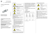
Included in the delivery contents are:
•Radial piston motor as per order confirmation
The following ports are protected with protective plug/threaded plug and protective
covers.
•Standard
– main ports A and B
– drain port L
•Where applicable
– brake port Z
– 2-speed port X
– filler port F (metal plug)
Fig. 1: Radial piston motors with various port protection

16/56 About this product
Bosch Rexroth AG, MCR Series 30, 31, 32, 33 and 41, RE 15215-01-B/11.2015
5 About this product
5.1 Performance description
A radial piston motor converts fluid flow into mechanical rotation. It has been
designed for mobile and stationary applications.
Refer to the relevant data sheet listed at chapter 1.2 for the technical data, operating
conditions and operating limits of the radial piston motor.
5.2 Product description
The MCR is a hydraulic motor with pistons arranged radially within a rotary group. It
is a low-speed, high torque motor which operates according to the multiple stroke
principle and delivers torque directly to the output shaft. MCR motors can be used
both in open and closed circuits.
In the open circuit, the hydraulic fluid flows from the reservoir to the hydraulic
pump from where it is transported to the hydraulic motor. From the hydraulic
motor, the hydraulic fluid flows directly back to the reservoir. The output direction
of rotation of the hydraulic motor can be changed, e.g. by a directional valve.
In the closed circuit, the hydraulic fluid flows from the hydraulic pump to the
hydraulic motor and from there directly back to the hydraulic pump. The output
direction of rotation of the hydraulic motor is changed, e.g. by reversing the flow
direction in the hydraulic pump. Closed circuits are generally used for hydrostatic
transmission in mobile applications.
5.2.1 Section of the radial piston motor
6
1
8 2
9
7
5
4
3
Fig. 2: Typical section of a MCR motor with holding brake
1 Front case
2 Rear case
3 Piston
4 Cylinder block
5 Cam
6 Output shaft
7 Flow distributor
8 Roller
9 Holding brake or end
cover
Open circuit
Closed circuit

About this product 17/56
RE 15215-01-B/11.2015, MCR Series 30, 31, 32, 33 and 41, Bosch Rexroth AG
5.2.2 Functional description
Fig. 3: MCR motor section
A radial piston motor consists of a two part housing(1, 2), rotary group(3, 4),
cam(5), output shaft(6) and flow distributor(7).
It converts hydrostatic energy into mechanical energy.
Hydraulic fluid is directed from the motor inlet port in the rear case(2) via the
flow distributor(7) through galleries to the cylinder block(4). Pressure increases
in the cylinder bore which forces the radially arranged pistons (3) outwards. This
radial force acts via the rollers (8) against the profile on the cam ring (5) to create a
rotary torque. This torque is transferred to the output shaft (6) via the splines in the
cylinder block (4).
If the torque exceeds the shaft load, the cylinder block turns, causing the pistons to
stroke (working stroke). Once the end of a stroke is reached the piston is returned
to its bore by the reaction force at the cam (return stroke) and the fluid is fed to the
motor outlet port in the rear case.
The output torque is produced by the force resulting from the pressure and piston
surface. It increases with the pressure difference between the high- and low-
pressure side.
The output speed depends on the displacement and is proportional to the inward
flow.
The number of working and return strokes corresponds to the number of lobes on
the cam multiplied by the number of pistons.
Working
stroke
Feed Return
Return
stroke
Fig. 4: Torque generation
Motor function
BA
AB
L
6845
3
12DD7E

18/56 About this product
Bosch Rexroth AG, MCR Series 30, 31, 32, 33 and 41, RE 15215-01-B/11.2015
The cylinder chambers(E) are connected to ports A and B via the axial bores and
the annular passages(D).
Tapered roller bearings capable of transmitting high axial and radial forces are fitted
as standard, except on Hydrobase motors (half motor without front case).
In certain applications there may be a requirement to freewheel the motor. This may
be achieved by connecting ports A and B to zero pressure and simultaneously
applying a pressure of 2bar to the housing through portL. In this condition, the
pistons are forced into the cylinder block which forces the rollers to lose contact
with the cam thus allowing free rotation of the shaft.
In mobile applications where vehicles are required to operate at high speed with low
motor loads, the motor can be switched to a low-torque and high-speed mode. This
is achieved by operating an integrated valve which directs hydraulic fluid to only one
half of the motor while continuously re-circulating the fluid in the other half. This
"reduced displacement" mode reduces the flow required for a given speed and gives
the potential for cost and efficiency improvements. The motor maximum speed
remains unchanged.
Rexroth has developed a special spool valve to allow smooth switching to reduced
displacement whilst on the move. This is known as "soft-shift" and is a standard
feature of 2W motors. The spool valve requires either an additional sequence valve or
electro-proportional control to operate in "soft-shift" mode.
ABX
L
15 bar
12 bar
Fig. 5: 2-speed motor schematic
In a closed circuit, the same hydraulic fluid continuously flows between the pump
and the motor which could lead to overheating of the hydraulic fluid.
The function of the flushing valve is to replace a proportion of the hydraulic fluid in
the closed circuit with that from the reservoir. When the hydraulic motor is operated
under load, either in the clockwise or anti-clockwise direction, the flushing valve
opens and takes a fixed flow of fluid through an orifice from the low pressure side
of the circuit. This flow is then fed to the motor housing and back to the reservoir
normally via a cooler. In order to charge the low pressure side of the circuit, cool
fluid is drawn from the reservoir by the boost pump and is fed to the pump inlet
through the check valve. Thus the flushing valve ensures a continuous renewal and
Flow paths
Bearings
Freewheeling
Two speed operation (2W)
Flushing valve

About this product 19/56
RE 15215-01-B/11.2015, MCR Series 30, 31, 32, 33 and 41, Bosch Rexroth AG
cooling of the hydraulic fluid. The flushing feature incorporates a relief valve which
is used to maintain a minimum boost pressure and operates at a standard setting of
14bar.
Different orifice sizes may be used to select varying flows of flushing fluid between
1.6 to 14l/min (based on a boost/charge pressure of 25bar). For all available
options refer to flushing information sheet 15225-01.
A (B)
B (A)
Fig. 6: Flushing schematic
NOTICE! Danger from improper use of the holding brake!
Product can be damaged!
▶ The holding brake is designed solely for static use and should not be applied
whilst the motor is rotating.
Fig. 7: Holding brake section
As a safety requirement in mobile applications a parking brake may be provided to
ensure that the motor cannot turn when the machine is not in use.
The brake is mounted by the way of the rear case(2) and brake shaft(16).
A disc pack(11), with alternate discs splined to the brake shaft and brake housing,
is compressed by the force of a disc spring(10) acting through a piston(12). The
friction between the discs generates a holding torque.
Holding brake
(multi-disc brake)
2 9
12
10
11
14
15
13
16
Z

20/56 About this product
Bosch Rexroth AG, MCR Series 30, 31, 32, 33 and 41, RE 15215-01-B/11.2015
When fluid is fed via the brake portZ into the annular area(9), the pressure on the
underside of the piston rises, opposing the spring force.
If sufficient pressure is applied, the piston moves to the right, removing the
compression on the disc pack and allowing the motor to turn freely.
When the pressure is removed the spring forces the piston back to the left and once
again compresses the disc pack.
Thus, the brake is fail-safe.
Manual release of holding brake:
In case of hydraulic system failure, the brake may be manually released by loosening
the end cover screws(13), or by removing plug(14), where present, and inserting a
puller into the tapped hole on the brake piston(15).
NOTICE! Danger from improper use of the holding brake!
Product can be damaged!
▶ The holding brake is designed solely for static use and should not be applied
whilst the motor is rotating.
Fig. 8: Holding brake section MCR-T
The brake is mounted by the way of the front case(2) and drive shaft(16).
A disc pack(11), with alternate discs splined to the drive shaft and front case, is
compressed by the force of a disc spring(10) acting through a piston(12). The
friction between the discs generates a holding torque.
When fluid is fed via the brake portZ into the annular area(9), the pressure on the
underside of the piston rises, opposing the spring force.
If sufficient pressure is applied, the piston moves to the right, removing the
compression on the disc pack and allowing the motor to turn freely.
When the pressure is removed the spring forces the piston back to the left and once
again compresses the disc pack.
Thus, the brake is fail-safe.
Holding brake
(multi-disc brake) MCR-T
9
11
16
2
12
10
/