Superabrasive L21-X, XGFI Owner's manual
- Category
- Floor Machine
- Type
- Owner's manual

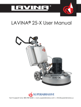
LAVINA® 21-X User Manual
Tech Support Line: 800-987-8403 | www.superabrasive.com | [email protected]

Superabrasive User Manual Original Language Lavina® 21-X 9/2018
2

Superabrasive User Manual Original Language Lavina® 21-X 9/2018
3
WARRANTY AND RETURNS
WARRANTY POLICY FOR LAVINA® X MACHINES
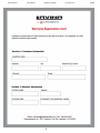
A warranty card must be submitted to Superabrasive within 30 days of purchase in order for the foregoing warranty to apply.
You can either mail a hard copy of the warranty card or submit it electronically - see page 2.
Superabrasive warrants, from the time of delivery and receipt by the original customer, new and unused products sold by
Superabrasive or Superabrasive-appointed distributors or dealers. Goods shall be free from defects in materials and
workmanship. Superabrasive or a Superabrasive-appointed repair facility shall either replace or repair any defects in the
Goods resulting from faulty design, materials, or workmanship. Products repaired or replaced during the warranty period
shall be covered by the foregoing warranty for the remainder of the original warranty period, or ninety (90) days from date
of the repair or shipment of the replacement, whichever is longer. Spare parts for repair will be either new or equivalent to
new.
Warranty period shall be 2 years from the time of delivery and receipt by the original customer, or 600 operating hours on
the machine - whichever occurs first. Superabrasive will cover the shipping charges for the transportation of the machine to
Superabrasive (or an approved repair facility) and back to the customer (within the contiguous 48 States) in the event that
the damage occurs and is reported within 200 operating hours. Shipping charges, if covered by Superabrasive, must be
agreed upon in advance and approved by Superabrasive. Thereafter, the customer will have to cover the shipping charges
to Superabrasive and back. Superabrasive will not warranty Goods after a period of 2 years from the time of delivery and
receipt by the original customer, or 600 operating hours on the machine - whichever occurs first.
Superabrasive shall not be liable for any defects that are caused by circumstances that occur after the Goods have been
delivered and whilst the Goods are in the possession of the purchaser. Furthermore, the warranty does not include
normal wear and tear or deterioration. Wear parts are not warranted. Superabrasive is not liable for defects arising out of
use of non-OEM parts.
The Warranty is void if the purchaser has not followed the maintenance plan stipulated by the machine’s manual and
warranty card. The warranty is void if the purchaser repairs said Goods himself, or if repairs are conducted by a repair
facility that is not approved by Superabrasive. Superabrasive’s liability does not cover defects which are caused by faulty
maintenance, incorrect operation, faulty repair by the purchaser, or by alterations conducted without Superabrasive’s prior
written consent. The same applies to any alterations of the Goods or services performed by another party other than
Superabrasive, a Superabrasive-appointed distributor, or a Superabrasiveapproved repair facility. The warranty is not
applicable on a defect that arises due to tools or parts that are not original to Superabrasive. Replaced defective parts shall
be placed at Superabrasive’s disposal and shall become property of Superabrasive. If such defective parts are replaced
within the warranty period, the shipping charges will be covered by Superabrasive. In warranty complaint cases, when no
defects are found for which Superabrasive is liable, Superabrasive shall be entitled to compensation for the labor, material
cost, and shipping charges, incurred by Superabrasive as as a result of the complaint. The warranty herein is non-
transferable, and only applies to the original owner or purchaser of the machine.
RETURN POLICY FOR LAVINA® X MACHINES
The Lavina® X machines may be returned, subject to the following terms:
In no case, a machine is to be returned to Superabrasive Inc. for credit or repair without prior authorization. Please
contact Superabrasive Inc. or your local distributor for an authorization and issuance of a return authorization number.
This number along with the serial number of the machine must be included on all packages and correspondence.
Machines returned without prior authorization will remain property of the sender and Superabrasive Inc. will not be
responsible for them. No machines will be credited after 90 days from the date of invoice.
All returns must be shipped freight prepaid. Returned machines may be exchanged for other equipment or parts of equal
dollar value. If machines are not exchanged, they are subject to a fifteen percent (15%) restocking fee
.

Superabrasive User Manual Original Language Lavina® 21-X 9/2018
4
TABLE OF CONTENTS
WARRANTY AND RETURNS................................... 3
1. GENERAL INFORMATION ...................................... 5
Manufacturer ............................................................. 5
General Description .................................................. 5
Machine characteristics ............................................. 5
Lavina 21 Main design .............................................. 5
ENVIRONMENTAL CONDITIONS ........................... 5
Electrical Connection ................................................ 5
Vacuum Connection .................................................. 6
Technical Data .......................................................... 6
Vibrations .................................................................. 6
Label Data ................................................................. 6
Customer Service ...................................................... 6
2. SAFETY INSTRUCTIONS ........................................ 7
Recommended Use ............................................. 7
Prohibited Use ........................................................... 7
Preparation for work .................................................. 7
protection Devices ..................................................... 7
Arrest Functions ................................................... 7
Safe Use.................................................................... 7
Residual Risks .......................................................... 7
Before You Begin ...................................................... 7
Operating Machine .................................................... 7
After Work is completed ............................................ 7
The Work Area .......................................................... 7
PERSONAL PROTECTIVE Equipment (ppe
Always wear safety 7
Operator .................................................................... 7
3. HANDLING AND TRANSPORTATION .................... 8
Adjusting the column angle ....................................... 8
Adjusting the handle .................................................. 8
Preparing the machine for transportation .................. 9
Storage ...................................................................... 9
4. OPERATION ............................................................. 9
Preliminary Controls .................................................. 9
ADJUSTING AND MOUNTING TOOLS ................... 9
Plug and cable ........................................................ 10
Control Board .......................................................... 10
Starting the Machine ............................................... 10
Operating the Machine ............................................ 10
Stopping the Machine ............................................. 11
5. TOOLS AND ACCESSORIES ................................ 11
Weights ................................................................... 11
Tool holder key ........................................................ 11
Foam Plate .............................................................. 11
Security plate for Quickchange pads ....................... 11
6. POPULAR TOOLS .................................................. 12
RECOMMENDED TOOLS ....................................... 12
7. MAINTENANCE AND INSPECTION ...................... 13
Cleaning ................................................................... 13
Check Daily .............................................................. 13
Check and replace Every 200 Working Hours......... 13
Check and replace Every 400 Working Hours......... 13
Vacuum .................................................................... 13
Water Leaks ............................................................. 13
Mechanical Parts ..................................................... 13
ELECTRICAL SYSTEM ........................................... 14
ELECTRICAL SCHEME .......................................... 14
ELECTRICAL SCHEME for GFCI outlet ................ 15
8. TROUBLESHOOTING ............................................ 16
Index of problems and Solutions ............................. 16
8.1 Replacing power cord and plugs ....................... 16
8.2 DISMOUNTING AND MOUNTING TOOL
HOLDER TO CHANGING V-RINGS AND FELT-
RINGS ...................................................................... 16
8.3 DISASSEMBLING AND MOUNTING TOOL
HOLDER TO CHANGE BUFFERS AND ELASTIC
ELEMENT ................................................................ 17
8.4 Tensioning used planetary Belt ......................... 18
8.5 Mounting and tensioning a new planetary belt .. 19
ORIGINAL TENSION ............................................... 19
8.6 TENSIONING AND REPLACING THE Main
BELT ........................................................................ 19
8.7 REPLACING THE PULLEY UNITS ................... 20
8.8 Motor Connection .............................................. 21
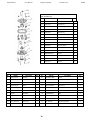
9. SPARE PARTS ....................................................... 21
1. LAVINA®21-X General Parts .................................... 22
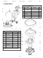
2. LAVINA®21-X Top cover parts 1 ............................... 22
3. LAVINA®21-x Guard parts ....................................... 23
3. LAVINA®21-x Guard parts ....................................... 23
4. LAVINA®21-X top cover Parts 2 ............................... 23
5. LAVINA®21-X Planetary drive Parts ......................... 24
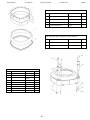
6. LAVINA®21-x bottom cover Parts ........................... 25
7. LAVINA®21-x TRANSMISSION BELT PARTS ............... 26
8. LAVINA®21-x PULLEY UNIT PARTS............................ 27
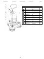
9. LAVINA® 21-X Tool Holder Parts .............................. 28
/see also fig.8.3.12/ ................................................... 28
10. LAVINA®21-X CARRIAGE PARTS ............................. 28
11. Lavina® 21-X ELECTRICAl Box Parts 100-120 Volt .... 30
11. Lavina® 21-X ELECTRICAl Box Parts 100-120 Volt for
GFCI outlet............................................................... 31

Superabrasive User Manual Original Language Lavina® 21-X 9/2018
5
1. GENERAL INFORMATION
This owner’s manual is intended for the operator of the Lavina® 21-X machine, the servicing technician as well as for anyone
involved with operating or servicing the machine. We recommend that you read the instructions very carefully and follow them
strictly. The manual includes information about assembling, using, handling, adjusting and maintaining your Lavina® 21-X
floor grinding and polishing machine.
MANUFACTURER
Superabrasive was founded in 1987, as a manufacturer of high quality diamond tools for the stone and concrete industry.
Today, Superabrasive is one of the world’s leading companies in the production of diamond tools and floor grinding
machinery. At Superabrasive, we strive to deliver the very best solutions to our customers, and enable them to work more
efficiently.
GENERAL DESCRIPTION
The Lavina® 21-X machine is intended for grinding, polishing, and buffing concrete, marble, granite, limestone, and terrazzo
surfaces with diamond tools. Additionally, the machine could be used for grinding wood floor surfaces.
The Lavina® 21-X is a three-disc machine, which can be used for wet or dry applications
For best results, only use tools manufactured or recommended by Superabrasive and its distributors.
The Lavina® 21-X machine is manufactured and fitted for the above-mentioned applications only! Every
other use may possess risks to the persons involved.
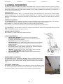
MACHINE CHARACTERISTICS
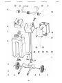
The Lavina® 21-X is made of two main component sections
LAVINA 21 MAIN DESIGN
• The two main components are the main head (1) and carriage (2).
• The handle on the frame is adjustable in height and allows the operator
to work in a correct and safe posture.
• The controls are positioned on top of the frame.
• The electrical box (fig.1.2) contains the electrical switches. The motor feeding
cable and the main feeding cable are plugged in the socket located on the
bottom of the frame.
• The water tank is on the opposite side of the frame, so that the weight of the
water has no influence on the operation of the machine. The frame weight, on
the other hand, is fully absorbed by the driving wheels.
• The motor, mounted on the base plate, drives the three heads with a belt
system. The planetary head is driven by a second belt.
• The self-leveling guard is designed to maintain contact with the surface,
regardless of tool height.
ENVIRONMENTAL CONDITIONS
The temperature range for operating the LAVINA® X machine outdoors is between 41°F
and 86°F or 5°C and 30°C. Never use the LAVINA® X machine during rain or snow when
working outdoors. When working indoors, always operate the machine in well-ventilated
areas.
ELECTRICAL CONNECTION
The voltage (Volt) and current (Ampere) are displayed on a label on the electrical control
box to avoid any incorrect connection. Refer to these before connecting the power. To
avoid electrical shocks, make sure the ground power supply is functioning properly.
Figure 1.2
Figure 1.1

Superabrasive User Manual Original Language Lavina® 21-X 9/2018
6
VACUUM CONNECTION
A connection for a vacuum dust extractor is located on the carriage. The LAVINA® X machine does not include a vacuum
dust extractor. The customer must purchase the vacuum dust extractor separately. The hose of the vacuum extractor
must be Ø 50.8 mm and can be glided over the pipe. The vacuum dust extractor must be adapted for floor grinders and
have a minimum air displacement of 320 m3/h with a negative vacuum of 21 kPa.
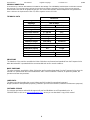
TECHNICAL DATA
VIBRATIONS
The vibrations of the machine are within the limits of directives and harmonized standards from the European Union
when the Lavina® X is operated with the recommended tools and in normal conditions.
NOISE EMISSIONS
The noise emissions are within the limits of directives and harmonized standards from the European Union when the
Lavina® X is operated with the recommended tools and in normal conditions. However, as previously stated, the
operator must wear ear protectors.
.
LABEL DATA
The data on the label provides the correct Voltage and kW (needed for operational purposes);
Weight (needed for transportation purposes); production year and serial number (needed for maintenance purposes).
CUSTOMER SERVICE
For customer assistance and technical support call your local distributor or call Superabrasive Inc. at
1-800-987-8403 or visit us at: www.superabrasive.com , where you can download a copy of this manual.
Lavina 21-X
Voltage/Hz
1 ph x 115 V 50- 60Hz
Amperage
Max 16 Amps
Power
1,8 kW
2.45 hp
Tool holder rpm
300 - 500 rpm
Working width
508 mm
19.7”
Tool holder diameter
3 x 178 mm
3 x 7”
Tool diameter
3 x 178 mm
3 x 7”
Weight
99 kg
219 lbs
Grinding pressure
51 kg
113 lbs
Additional weight
max 4x8 kg
4x 18.5 lbs
Application
wet and dry
Vacuum hose port
Ø 50,8 mm
2”
Water tank capacity
20 l
5.2 gal
Water feed
Peripheral
Machine LxWxH
1500x540x1070 mm
59.1”x21.3” x42”
Packing crate LxWxH
1100x750x780 mm
43.3”x29.5”x30.7”

Superabrasive User Manual Original Language Lavina® 21-X 9/2018
7
2. SAFETY INSTRUCTIONS
RECOMMENDED USE
The Lavina®X machine is designed and manufactured to grind
and polish concrete, terrazzo and natural stone floors. It can be
used for renovations as well as for polishing. The machine is
designed for dry or wet use. When using it dry, use a vacuum of
appropriate size. For more information, please refer to the
chapter on handling the vacuum
connection.
PROHIBITED USE
The machine MUST NOT be used:
• For applications different from the ones stated in the
General Description chapter.
• For not-suitable materials. In environments which:
• Possess risks of explosion
• Possess high concentration of powders or oil substances in
the air Possess risks of fire Feature inclement
conditions.
• Possess electromagnetic radiation.
• The machine should be not connected to electricity when
changing the tools
PREPARATION FOR WORK
Make sure that:
You have closed the work area, so that no person
unfamiliar with operating the machine can enter the area
The tool plate and tools are adjusted to the machine
properly
There are no missing parts of the machine
The machine is in upright working position
The protection devices are working properly.
The electrical cable is free to move and follow the machine
easily. In order to keep the electrical cable from being
damaged, no vehicle should cross the zone where electrical
cables are situated.
PROTECTION DEVICES
• The machine is equipped
with several protection devices including the following:
• An emergency stop button
• A protection skirt and a hood for protecting the tool plates.
• These devices protect the operator and/or others persons
from potential injuries. Do not remove them. On the
counterry, before using the machine, please ensure that all
protection devices are
mounted and function
properly.
ARREST FUNCTIONS
Functions of arresting of the machine are following:
• Button to stop the motor (category 1)
• Emergency button (category 1)
SAFE USE
• The Lavina® 21-X is designed to eliminate all risks corre
The Lavina® 21-X is designed to eliminate all risks
correlated with its use. However, it is not possible to
eliminate the risks of an eventual accident with the
machine. Unskilled or uninstructed operator may cause
correlated residual risks. Such risks are:
• Position Risks due to operator’s incorrect working position
• Tangling up Risks due to wearing inappropriate working
clothes
• Training Risks due to lack of operational training
NOTE: In order to reduce all consequences of the
abovementioned risks, we advise that machine operators will
follow the instructions in the manual at all times.
RESIDUAL RISKS
• During the normal operating and maintenance cycles, the
operator is exposed to few residual risks, which cannot be
eliminated due to the nature of the operations.
BEFORE YOU BEGIN
• Working area must be clear
from any debris or objects.
• A first-time operator must always read the manual and pay
attention to all safety instructions.
• All electric connections and cables must be inspected for
potential damages.
• Ground wire system of the power supply must be also
inspected.
• Perform general daily inspections of the machine and
inspect the machine before each use.
• Always inspect the safety devices:
• The emergency break must be clear and working
• The tool protector must be working The machine must
be clean Never operate the machine in the rain!
• Confirm that there are no missing parts especially after
transportation, repair or maintenance.
• Before filling the water tank with water make sure the
machine is not working and the main switch is turned off.
• Before turning on the machine make sure that the base is
placed on the floor, the machine MUST NOT be in an
upright position when turned on!
OPERATING MACHINE
• When operating the Lavina® 21-X make certain that there is
no one, but you around the machine.
• Never leave the machine unattended while working.
The electrical cable must move freely and must be damage-
free and should not go below the machine.
The water hose must move freely and must be damage-free.
• Check if the floor, you work on, is not too uneven. If this is
the case, it may damage the machine.
AFTER WORK IS
COMPLETED
Clean the machine and its surroundings properly
• Empty and clean the water tank
• Unplug the machine and wind up the electrical cable
• Store the machine in a safe place
THE WORK AREA
• Make certain that people or vehicles do not enter the work
area.
• Avoid cables and hoses being in the way.
• Always check the floor for debris
PERSONAL PROTECTIVE EQUIPMENT (PPE
ALWAYS WEAR SAFETY
• Always wear safety shoes
when working with the
machine.
• Always wear ear protectors when working with the machine.
• All personnel in the immediate work area must wear safety
glasses with side shields.
• Always wear safety gloves when changing the tools.
• Always wear clothes suitable for the work environment.
OPERATOR
The Lavina®21-X machine.

Superabrasive User Manual Original Language Lavina® 21-X 9/2018
8
The operator must know the machine’s work environment.
Only one operator at a time can work with the machine.
The operator must be properly trained and well instructed
prior operating the machine.
The operator must understand all the instructions in this
manual.
The operator must understand and interpret all the drawings
and designs in manual.
The operator must know all sanitation and safety regulations
pertaining to the operation of
The operator must have floor grinding experience.
The operator must know what to do in case of emergency.
The operator must have an adequate technical knowledge
and preparation.
3. HANDLING AND TRANSPORTATION
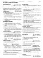
ADJUSTING THE COLUMN ANGLE
ADJUSTING THE COLUMN ANGLE
You can adjust
the angle of the
column for
several purposes,
such as
transporting or
flipping the
machine for tool
change. Making
the column
straight makes it
easier to work in
narrow places (Fig. 3.1, Fig. 3.2).
To adjust the column, turn the lever lock and rotate the column (Fig. 3.3, Fig. 3.4).
ADJUSTING THE HANDLE
The Handle on the frame is adjustable in height and allows the operator to work in a correct and safe posture. To
adjust, simply pull the locking pin (fig.3.5) and move the frame. A loaded spring will return the pin and lock
the handle in any of several positions (fig.3.6). Choose the vertical position to easily move the machine.
Figure 3.3
Figure 3.4
Figure 3.1
Figure 3.2
Figure 3.5
Figure 3.6

Superabrasive User Manual Original Language Lavina® 21-X 9/2018
9
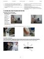
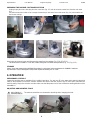
PREPARING THE MACHINE FOR TRANSPORTATION
Unplug Unplug the motor cable plug from the control box (Fig. 3.7) and disconnect the water hose from the main head
(Fig.
3.8). Wind the electrical cable on the carriage. Release the pin sets at the base of the motor (Fig. 3.9), which attach the
head to the carriage.
Disconnect the vacuum hoses and dismount the head from the carriage (Fig. 3.10) (Fig. 3.11).
The head of the Lavina® 21-X has two handles designed to facilitate transportation (Fig. 3.11, Fig. 3.12).
STORAGE
Always store and transport the LAVINA® X machine in a dry place. Never transport the LAVINA® X machine
unprotected; it may be damaged if transported unprotected during rain or snow.
4. OPERATION
PRELIMINARY CONTROLS
Inspect the working area as explained in the safety instructions. For wet use, fill in the water tank when the electrical
cable is disconnected. Connect the vacuum extractor and ensure that the vacuum hose is clear and it will follow the
machine easily. Plug in the machine and also make sure that the power cord is free to follow the working direction of the
Lavina®21-X.
ADJUSTING AND MOUNTING TOOLS
The machine should be not connected to electricity when changing the tools.
Figure 3.7
Figure 3.8
Figure 3.9
Figure 3.10
Figure 3.12
Figure 3.11
Figure 4.1
Figure 4.2

Superabrasive User Manual Original Language Lavina® 21-X 9/2018
10
To change tools flip the carriage over to the floor. Ensure first if the handle (Fig. 4.1) or the column (Fig. 4.2) is in the
upright position.
Mount the tools only after ensuring that there is enough
diamond bond material left. Be sure that the plates are
always clean before mounting.
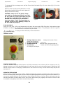
WARNING: Always Secure the Quick Change
tools with the security plate (Fig.4.3), lock with
the tool holder key (Fig.4.4) and make sure that
the butterfly is securely locked at 90 degrees.
Diamond tools with Velcro are attached on
three foam plates (7 inch). The foam plates are
mounted on the key lock (butterfly). Always use
the tool holder key (Fig.5.2).
PLUG AND CABLE
A plug (min. 16A; 110V, IP55) should be attached to the cable. We recommend H07BQ-F3x2,5mm² with maximum length
20 meters, according to the standards of the country where the machine will work. The yellow/green cable is the ground,
and should not be connected to any live terminal.
The plug should be attached by a licenced electrician. .
CONTROL BOARD
1. Working orking hours meter displays total number of hours
worked with the machine
2. Emergency/stop button stops motor
3. ON button-Power led starts the motor; lights green when on
4. Potentiometer Controls the RPM of the grinding plates
on a range of 300-500 rpm
STARTING THE MACHINE
Follow the directions in chapter Safety Devices and Safety Instructions. Next, release (pull) the emergency stop (2),
allowing the motor to run. Check the potentiometer (4), and ensure that it is set to the working speed. If working wet, add
water to the floor surface. If working dry, instead switch on the vacuum unit. Finally, hold the machine firmly and push the
start button (3)
OPERATING THE MACHINE
Guide machine in straight lines across the floor, slightly overlapping the previously completed surface with each new line.
Work at a constant speed, allowing the tools time to work at a speed appropriate for the tools’ grit size. Avoid vibrations. Do
not stop the machine while tools are still running as they will mark the surface of the floor. When working wet, open the
water tank periodically to release water onto the floor surface. When working dry, regularly check the floor surface for dust
accumulation, and regularly check that the vacuum works properly.
Figure 4.3
Figure 4.4
Figure 4.5

Superabrasive User Manual Original Language Lavina® 21-X 9/2018
11
STOPPING THE MACHINE
The stopping of the machine must be done gradually until the motor stops. Do not stop moving the machine before arresting
the motor as the tools could damage the surface. To stop push the emergency/stop button (3).
Remember not to hold the machine in one spot before turning off the motor.
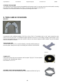
5. TOOLS AND ACCESSORIES
WEIGHTS
Superabrasive offers additional weights of 18.5 lbs or 8 kg (Fig.5.1). The weights stack on the 3 posts around the outer
bowl or on top of each other. The additional weights depend on the tools; it is not always possible to add weights. Some
tools work too aggressively can cause the machine to stop. No more than 4 weights should be added. They can be ordered
with item number L21-50.00.00.
TOOL HOLDER KEY
The tool holder key (Fig. 5.2) is used for adjusting, mounting and dismounting of
the foam plates. Always use the key for mounting. Item number is A03.00.00.00
FOAM PLATE
Diamond tools with Velcro are mounted on the foam plate 7“(Fig.5.3). The foam plate is
mounted on the “QuickChange” System.
Item number is LV-7-FP-S
SECURITY PLATE FOR QUICKCHANGE PADS
Plate used to ensure the “Quickchange” pads. Item number is A38.00.04 (Fig.5.4)
Figure 5.1
Figure 5.4
Figure 5.2
Figure 5.3

Superabrasive User Manual Original Language Lavina® 21-X 9/2018
12
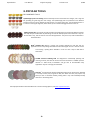
6. POPULAR TOOLS
RECOMMENDED TOOLS
QuickChange System and Tooling feature extremely fast and convenient tool changes, and a long tool
life, providing for great long‐term cost savings. The QuickChange pads are produced in four different
bonds for super hard, hard, medium and soft concrete, in a variety of grit sizes. They are offered with 1 or
2 buttons or rectangular segments, which allows you to customize the aggressiveness of the cut.
Calibra grinding discs: our popular ceramic bond discs are designed for the removal of difficult scratches
and they save you valuable time by eliminating the need for multiple passes with metal tools. They can
be used wet or dry, and are best for hard concrete applications. They are 3‐inch, with included Velcro
back attachment.
NATO® polishing discs feature a special resin formula designed for both wet and dry
applications and a unique design with wide channels allowing for work on a cleaner surface
and ensuring a quality polish. Available in 3 and 4 in sizes. They are with Velcro
attachment.
V‐HARR® Premium Polishing Pads are designed for mechanically polishing and
restoring concrete; also ideal for terrazzo and hard stone floors. V‐HARR® pads are
offered in a wide variety of diameters and grit sizes to accommodate many
applications. Dry use is strongly recommended.
Shine Pro® are high quality diamond‐integrated pads for floor maintenance. Available
in a variety of sizes, they are great for daily use. When used wet, they require only
water (no wax or chemicals needed), making them a very environmentally‐friendly
solution for maintaining floors.
Use Only Superabrasive’s Recommended Tools. For More Tooling Options, Visit www.superabrasive.com

Superabrasive User Manual Original Language Lavina® 21-X 9/2018
13
7. MAINTENANCE AND INSPECTION
CLEANING
Keep your machine clean. Cleaning the machine on a regular basis will help detect and solve potential problems before they
cause damage to the machine. Most importantly, check and clean the tool plate connections, power cord and plugs, vacuum
hoses and water tank.
CHECK DAILY
After operating the Lavina® X machine, the operator should conduct a visual inspection of the
machine. Any defect should be solved immediately. Pay attention to power cords, plugs and
vacuum hoses, loose bolt or screws.
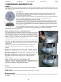
Tool holders: Buffers and elastic element are consumables and must be visually checked daily and
replaced if needed. See that flanges or discs are mounted and locked well in place.
The key lock holders (butterflies) should be also checked.
Check the rubber buffers and fixing of the holders. The flange holding the buffers (Fig.7.1-1) has to
be firmly fixed to the unit. A gap seen there means that there are loose screws fixing the holder.
The screws have to be tightened immediately for safe operation. Working with loose screws on the
holder could also cause bad damages on the machine. Tightening force on the screws should be
22...25 N.m(16...18 lbf.ft).
It is very important to regularly check the screws (Fig.7.1-2) that fix the “Quickchange” holder
to the safety part, so that the holder will not fly away if the buffers get damaged.
“Quickchange” should also be cleaned.
CHECK AND REPLACE EVERY 200 WORKING HOURS
Every 200 working hours, the operator should inspect all parts of the machine
carefully. Most importantly, inspect and clean the tool plate connections,
power cord plugs, vacuum hoses and water tank. Check the guard assembly.
Make certain the wheels are clean and rotate properly. Inspect the control
buttons. If there are defective control parts, they should be replaced
immediately. Replace worn vacuum and water hoses.
Separate the carriage from the main head. Unscrew the four bolts (Fig.7.2),
and remove the upper cover (Fig.7.3). Check the planetary driving belt, by
moving the main head, the belt should not slip on the Figure 7.2 planetary
(central) pulley.
Dismount the tool holders (See TROUBLESHOOTING), and replace all
parts (elastic element, buffers, sealer caps, “O” rings) that show any
damage.
Separate the carriage from the main head. Unscrew the four
bolts(Fig.7.2) and take the upper cover (Fig.7.3). Check the planetary
driving belt, by moving the main head, the belt should not slip on the
planetary /central/ pulley.
Dismount the tool holders (See TROUBLESHOOTING) and replace all
parts (elastic element, buffers, sealer caps, “O” rings) that have the
slightest damage.
CHECK AND REPLACE EVERY 400 WORKING HOURS
Besides the checks of 200 working hours, replace sealer and V-rings like
described in chapter “TROUBLESHOOTING - DISMOUNTING TOOL
HOLDERS TO CHANGE V-RINGS AND FELT-RINGS.
VACUUM
As stated previously, frequently check hoses and other parts for clogging.
WATER LEAKS
Replace any leaking parts immediately, as the water could damage your machine
MECHANICAL PARTS
Parts such as the belts, seal rings, cap rings, spiders, buffers and guard assembly are subject to wear and must be replaced
as needed.
Figure 7.1
Figure 7.2
Figure 7.3

Superabrasive User Manual Original Language Lavina® 21-X 9/2018
14
ELECTRICAL SYSTEM
Dust should not enter the control box as it will destroy the contacts. Remove (blow out) any dust present.
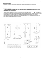
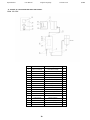
ELECTRICAL SCHEME
A plug should be attached to the cable (min. 16A; 110V, IP55) according to the standards of the country
where the machine will be operated.
The plug should be attached by a a licenced electrician. The yellow-green cable is ground.
We recommend that the cable is H07BQ-F3x2,5mm² with a maximum length of 20 meters. A socket (min. 16A; 110V IP55 )
should be attached to the cable according to the standards of the country where the machine will be operated.
When replacing the power cord or plugs, always use cords and plugs with the same specifications as the original ones.
Never use lower quality or different type cord and plugs.

Superabrasive User Manual Original Language Lavina® 21-X 9/2018
15
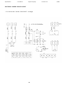
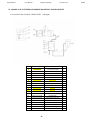
ELECTRICAL SCHEME FOR GFCI OUTLET
*** for machines after Serial No 1806L21X1871 and bigger

Superabrasive User Manual Original Language Lavina® 21-X 9/2018
16
8. TROUBLESHOOTING
INDEX OF PROBLEMS AND SOLUTIONS
8.1 REPLACING POWER CORD AND PLUGS
When replacing the plugs always use plugs with the same specifications as the original ones.
Never use lower quality or different type.
.
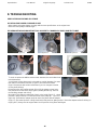
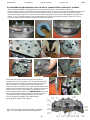
8.2 DISMOUNTING AND MOUNTING TOOL HOLDER TO CHANGING V-RINGS AND FELT-RINGS
To check or replace the buffers and the elastic elements, the tool holders have
to be dismounted.
You will need a 13mm deep metric socket with an outside diameter of no more
than 3/4in to unscrew the four bolts (Fig.8.2.1) and remove the holder
(Fig.8.2.2) When the tool holder is dismounted, you can change the sealers
(V-Ring and Felt-Ring).
By loosening four Hex cap flange bolts (Fig.8.2.3) the adaptor comes loose.
Unscrew the six screws of the cap (Fig.8.2.4) holding the felt-ring. Take out
the Felt-Ring, adaptor and V-Ring.
Mount the V-Ring with the smallest lip of the V to the inside (Fig.8.2.5) - simply
push the V-Ring so the top is on the same level as the pulley top Figure 8.2.7
(Fig.8.2.6). Then take the adaptor and push the V-Ring down with the adaptor
(Fig.8.2.7). The lowest lip of the V-Ring should only barely touch its gliding surface. Mount the adaptor and the Felt-Ring on
top (Fig.8.2.7). Always use the original bolts. Do not push the V-ring down with fingers.
Figure 8.2.1
19
Figure 8.2.2
Figure 8.2.3
Figure 8.2.5
Figure 8.2.4
19
Figure 8.2.7
Figure 8.2.6

Superabrasive User Manual Original Language Lavina® 21-X 9/2018
17
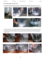
8.3 DISASSEMBLING AND MOUNTING TOOL HOLDER TO CHANGE BUFFERS AND ELASTIC ELEMENT
When the TOOL HOLDER is disassembled you can change defective parts – elastic element, buffers, etc.
Lift the locking pin (Fig.8.3.1) to dismount the retaining washer (Fig.8.3.2). Take out the screws on the buffers and the nuts of
the elastic element (Fig.8.3.3; Fig.8.3.4). Remove the elastic element from the QC plate (Fig.8.3.5). While the holder is
dismounted (Fig.8.3.6; Fig.8.3.7), clean the parts and replace the defective with new ones. Assemble the holder with new
buffers, screws, and elastic element. Put the retaining washer (Fig.8.3.8) and push the locking pin (Fig.8.3.9). This will
prevent the washer from falling while mounting the holder to the machine.
Mount the holder on the machine using the same socket as
mentioned in 8.2 (Fig.8.3.10;Fig.8.3.11). The retaining washer fits
into the central hole of adaptor and the four bolts into the thread
holes. The holder is centered on the outside diameter of the
adaptor. Ensure the connection of the holder on the forehead of the
adaptor and then tight evenly the four bolts. Tightening force of the
bolts has to be 22...25 N.m (16...18 lbf.ft). Mounting the holder
without retaining washer (Fig.8.3.2) is INADMISSIBLE because the
security system preventing the separation of part of the holder in
case of broken buffers and elastic element will not function!
You can change the butterfly of the holder without
dismounting the holder of the machine.
Fig.8.3.12 is 3-d section view of the holder, showing its
parts. The numbering is the same as in Spare parts.
Figure 8.3.1
Figure 8.3.2
Figure 8.3.3
Figure 8.3.6
Figure 8.3.7
Figure 8.3.4
Figure 8.3.5
Figure 8.3.8
Figure 8.3.9
Figure 8.3.12
Figure 8.3.10
Figure 8.3.11

Superabrasive User Manual Original Language Lavina® 21-X 9/2018
18
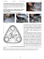
8.4 TENSIONING USED PLANETARY BELT
If the belt slips or breaks, separate the carriage from main head and disconnect the motor plug (Fig. 8.4.1), water
hoses (Fig. 8.4.2) (Fig. 8.4.3), and vacuum tubes. Unscrew the four bolts (Fig.8.4.4) and remove top cover (Fig.8.4.5).
If the belt only slipped, it can be retightened. Slightly loosen the two bolts and the nut of the tensioner (Fig. 8.4.6)(Fig.
8.4.7)(Fig. 8.4.8). Unscrew the stop nut (Fig. 8.4.9). Correct the belt tension using the nut. Fig.8.4.10 shows how to
measure the belt tension with an Optikrik I Device (Measuring range: 200-600 N) (Fig. 8.4.11). The tensioning force
should be 250N.
Figure 8.4.1
Figure 8.4.2
Figure 8.4.3
Figure 8.4.4
Figure 8.4.5
Figure 8.4.10
Figure 8.4.11
Figure 8.4.9
Figure 8.4.6
Figure 8.4.7
Figure 8.4.8

Superabrasive User Manual Original Language Lavina® 21-X 9/2018
19
8.5 MOUNTING AND TENSIONING A NEW PLANETARY BELT
Unscrew the two bolts and the nut of the tensioner (Fig. 8.4.6)(Fig.
8.4.7)(Fig. 8.4.8). Unscrew the stop nut and turn the tensioner to loosen
the belt (Fig. 8.4.9). Take off the old belt. Install the new belt (Fig. 8.5.1),
and replace the bolts and nut o. Do not forget to lock the tensioner
(Fig.8.4.10).
ATTENTION: NEVER “OVER” TENSION THE BELT, THE BELT
WILL BE DAMAGED AND IT WILL NEVER RECOVER ITS
ORIGINAL TENSION
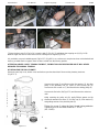
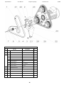
8.6 TENSIONING AND REPLACING THE MAIN BELT
The transmission of the machine has one timing belt
that rotates the three tools. To change the belt, remove
all holders and adaptors. There will be sealing to
remove as well. Carefully check any friction surfaces for
wear, and replace if necessary. To remove the bottom
cover, unscrew the bolts spaced around the edge of the
cover (Fig.8.6.1). While changing belts, it is
recommended to change all seals (O-Rings and seal
around cover)
Fig.8.6.3 shows the scheme of the belt. To remove the
belt (1), unscrew the bolt (5), the three nuts (2), and the
nut (3) such that the tensioner (6) can be turned around
the central axle. Clean the washers and surrounding
area, and check all bearings of pulley units or
tensioners for too much clearance or rolling noise).
Rotating the tensioner will allow the central distance to
be reduced in such a way that the timing belt may be
fitted without force. Installation with the use of force is
NOT permissible at any time as this can damage the
high quality, low stretch tension cord and other
components. This damage is often not visible. Put the
belts in pos.1 as per the scheme, paying attention to
their orientation and connection at every pulley. Loosen
nuts (3) to the end of the bolt and fully loosen the nuts
on the half-moon (2) (Fig. 8.6.4), allowing the rotation of
Figure 8.6.3 the tensioners with minimal force
Using nut (3) (Fig. 8.6.5), tighten the belt, verifying again the correct position of the belt, and the correct gearing in every
pulley.
Rotate the gear while tensioning to allow regular tension distribution along the belt. Measure the tension using a
Frequency Tension Tester (Optibelt 3 TT) (Fig. 8.6.6). Tension in span “А” of the belt should be 240-250Hz.
Figure 8.5.1
Figure 8.6.2
Figure 8.6.1
Figure 8.6.4
Figure 8.6.3

Superabrasive User Manual Original Language Lavina® 21-X 9/2018
20
Tighten the three nuts (2) (Fig. 8.6.4), screw the bolt (5) (Fig. 8.6.7) and tighten the stopping nut (4) (Fig. 8.6.8).
Measure again the tension of the belt to ensure nothing has changed (Fig. 8.6.6).
It is possible to use pre-installed support (Fig.8.6.3-7) (Fig.8.6.9) as a reference to stop the tensioner at the desired belt
tension, provided that the supports have not been moved from their factory position.
ATTENTION: NEVER “OVER” TENSION THE BELT, THE BELT WILL BE DESTROYED AND IT WILL NEVER
RECOVER ITS ORIGINAL TENSION
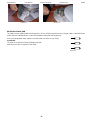
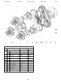
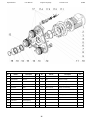
8.7 REPLACING THE PULLEY UNITS
Dismount guard, top cover, bottom cover and belts as previous described. Dismount the planetary tensioner.
(Fig.8.7.1-1).
Unscrew the screw (2) and dismount the front washer (3), the drive
pulley of the planetary belt (4), cotter (5) and security cap (6).
Unscrew the five screws on (7) and dismount the driving pulley (8).
Unscrew the five bolts (10)(Fig.8.7.2) and dismount the other two
units.
While mounting the pulley unit (8), apply lithium grease on the
shaft and remount the cotter (5), security cap (6), front washer (3)
and guiding washer of the planetary belt (4).
Tighten the screw (2) using the “blue” thread locking adhesive.
Tightening force on the bolts should be 9...11N.m
(6.6...8 lbf.ft).
Figure 8.6.5
Figure 8.6.6
Figure 8.6.7
Figure 8.6.9
Figure 8.6.8
Figure 8.7.1
Page is loading ...
Page is loading ...
Page is loading ...
Page is loading ...
Page is loading ...
Page is loading ...
Page is loading ...
Page is loading ...
Page is loading ...
Page is loading ...
Page is loading ...
-
 1
1
-
 2
2
-
 3
3
-
 4
4
-
 5
5
-
 6
6
-
 7
7
-
 8
8
-
 9
9
-
 10
10
-
 11
11
-
 12
12
-
 13
13
-
 14
14
-
 15
15
-
 16
16
-
 17
17
-
 18
18
-
 19
19
-
 20
20
-
 21
21
-
 22
22
-
 23
23
-
 24
24
-
 25
25
-
 26
26
-
 27
27
-
 28
28
-
 29
29
-
 30
30
-
 31
31


Superabrasive L21-X, XGFI Owner's manual
- Category
- Floor Machine
- Type
- Owner's manual
Ask a question and I''ll find the answer in the document
Finding information in a document is now easier with AI
Related papers
-
 Superabrasive L20-X Owner's manual
-
 Superabrasive L25-X Owner's manual
-
Superabrasive L16EU Owner's manual
-
 Superabrasive L16E Owner's manual
-
 Superabrasive L25LM-X Owner's manual
-
 Superabrasive L25LEB Owner's manual
-
 Superabrasive L20-S Owner's manual
-
 Superabrasive L25-S Owner's manual
-
 Superabrasive L20N-S Owner's manual
-
 Superabrasive L30LEB Owner's manual