SKYTRONIC 600.005 Owner's manual
- Category
- Multimeters
- Type
- Owner's manual
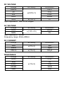
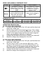
SKYTRONIC 600.005 is a 3 1/2 digits Digital multimeter intended for measuring DC and AC voltage, DC current, resistance, diodes, transistors, and to perform audible continuity test. Input impedance for the DC voltage measurement is 1MΩ; AC voltage measurement input impedance is 452KΩ and frequency range is 50Hz~200Hz; input impedance for resistance measurement is 1MΩ. Power is supplied by 12V battery. Device features low battery indication, over range indication, automatic zero adjustment and fuse protection.
SKYTRONIC 600.005 is a 3 1/2 digits Digital multimeter intended for measuring DC and AC voltage, DC current, resistance, diodes, transistors, and to perform audible continuity test. Input impedance for the DC voltage measurement is 1MΩ; AC voltage measurement input impedance is 452KΩ and frequency range is 50Hz~200Hz; input impedance for resistance measurement is 1MΩ. Power is supplied by 12V battery. Device features low battery indication, over range indication, automatic zero adjustment and fuse protection.


-
 1
1
-
 2
2
-
 3
3
-
 4
4
-
 5
5
-
 6
6
-
 7
7
-
 8
8


SKYTRONIC 600.005 Owner's manual
- Category
- Multimeters
- Type
- Owner's manual
SKYTRONIC 600.005 is a 3 1/2 digits Digital multimeter intended for measuring DC and AC voltage, DC current, resistance, diodes, transistors, and to perform audible continuity test. Input impedance for the DC voltage measurement is 1MΩ; AC voltage measurement input impedance is 452KΩ and frequency range is 50Hz~200Hz; input impedance for resistance measurement is 1MΩ. Power is supplied by 12V battery. Device features low battery indication, over range indication, automatic zero adjustment and fuse protection.
Ask a question and I''ll find the answer in the document
Finding information in a document is now easier with AI
Other documents
-
3B SCIENTIFIC PHYSICS E 1006809 Instruction Sheet
-
Mastech MS8321A User manual
-
Elenco M1000D Owner's manual
-
CEN-TECH Item 95670 Owner's manual
-
-
Rolls MU118 User manual
-
UNI-T UT39A Specification
-
Silverline 589681 User manual
-
Velleman VTSET24 User manual
-