Page is loading ...

IDC
2XX with Cold Carbonation
Operator’s Manual
Release Date: October 18, 2005
Publication Number: 621057403OPR
Revision Date: November 18, 2009
Revision: E
Visit the IMI Cornelius web site at www.cornelius.com
for all your Literature needs.
®

IDC
OPERATOR’S MANUAL
The products, technical information, and instructions contained in this manual are subject
to change without notice. These instructions are not intended to cover all details or varia-
tions of the equipment, nor to provide for every possible contingency in the installation,
operation or maintenance of this equipment. This manual assumes that the person(s)
working on the equipment have been trained and are skilled in working with electrical,
plumbing, pneumatic, and mechanical equipment. It is assumed that appropriate safety
precautions are taken and that all local safety and construction requirements are being
met, in addition to the information contained in this manual.
To inquire about current revisions of this and other documentation or for assistance with
any Cornelius product contact:
www.cornelius.com
800-238-3600
Trademarks and copyrights:
Aurora, Cornelius, FlavorFusion, Hydro Boost, Optifill, Pinnacle, and Vanguard are regis-
tered trademarks of IMI Cornelius Inc.
This document contains proprietary information and it may not be
reproduced in any way without permission from Cornelius.
Printed in U.S.A.
Copyright © 2005-2009, All Rights Reserved, IMI Cornelius, Inc.

TABLE OF CONTENTS
Safety . . . . . . . . . . . . . . . . . . . . . . . . . . . . . . . . . . . . . . . . . . . . . . . . . . . . . . . . . . . . . . . 1
Safety Instructions . . . . . . . . . . . . . . . . . . . . . . . . . . . . . . . . . . . . . . . . . . . . . . . . . . . 1
Read and Follow all Safety Instructions . . . . . . . . . . . . . . . . . . . . . . . . . . . . . . . 1
Recognize Safety Alerts . . . . . . . . . . . . . . . . . . . . . . . . . . . . . . . . . . . . . . . . . . . 1
Different Types of Alerts . . . . . . . . . . . . . . . . . . . . . . . . . . . . . . . . . . . . . . . . . . . 1
Safety Tips . . . . . . . . . . . . . . . . . . . . . . . . . . . . . . . . . . . . . . . . . . . . . . . . . . . . . . . . 1
CO
2 (Carbon Dioxide) Warning . . . . . . . . . . . . . . . . . . . . . . . . . . . . . . . . . . . . . . . . . 1
Start-up and Operating Instructions . . . . . . . . . . . . . . . . . . . . . . . . . . . . . . . . . . . . . . 2
Ice Drink Dispenser . . . . . . . . . . . . . . . . . . . . . . . . . . . . . . . . . . . . . . . . . . . . . . . . . . 2
Cleaning Instructions . . . . . . . . . . . . . . . . . . . . . . . . . . . . . . . . . . . . . . . . . . . . . . . . . . 2
Dispenser . . . . . . . . . . . . . . . . . . . . . . . . . . . . . . . . . . . . . . . . . . . . . . . . . . . . . . . . . 2
Cleaning Exterior Surfaces . . . . . . . . . . . . . . . . . . . . . . . . . . . . . . . . . . . . . . . . . 2
Cleaning Interior Surfaces . . . . . . . . . . . . . . . . . . . . . . . . . . . . . . . . . . . . . . . . . . 3
Beverage System (if applicable) . . . . . . . . . . . . . . . . . . . . . . . . . . . . . . . . . . . . . . . . 3
Cold Plate . . . . . . . . . . . . . . . . . . . . . . . . . . . . . . . . . . . . . . . . . . . . . . . . . . . . . . 3
Dispensing Valves . . . . . . . . . . . . . . . . . . . . . . . . . . . . . . . . . . . . . . . . . . . . . . . . 3
Product Tubing . . . . . . . . . . . . . . . . . . . . . . . . . . . . . . . . . . . . . . . . . . . . . . . . . . 4
Sanitize Post–Mix tank system . . . . . . . . . . . . . . . . . . . . . . . . . . . . . . . . . . . 4
Sanitize syrup lines, B–I–B Systems . . . . . . . . . . . . . . . . . . . . . . . . . . . . . . . . . . 4
Replenishing CO
2 Supply . . . . . . . . . . . . . . . . . . . . . . . . . . . . . . . . . . . . . . . . . . 5
Cleaning Dispensing Valve . . . . . . . . . . . . . . . . . . . . . . . . . . . . . . . . . . . . . . . . . 5
Maintenance . . . . . . . . . . . . . . . . . . . . . . . . . . . . . . . . . . . . . . . . . . . . . . . . . . . . . . . . . 6
Daily (or as required) . . . . . . . . . . . . . . . . . . . . . . . . . . . . . . . . . . . . . . . . . . . . . . . . . 6
Checking CO
2 Supply . . . . . . . . . . . . . . . . . . . . . . . . . . . . . . . . . . . . . . . . . . . . . 6
Checking for CO
2 and water leak . . . . . . . . . . . . . . . . . . . . . . . . . . . . . . . . . . . . 6
Monthly . . . . . . . . . . . . . . . . . . . . . . . . . . . . . . . . . . . . . . . . . . . . . . . . . . . . . . . . . . . 6
Yearly . . . . . . . . . . . . . . . . . . . . . . . . . . . . . . . . . . . . . . . . . . . . . . . . . . . . . . . . . . . . 6
Water Pump Maintenance (or after water system disruption) . . . . . . . . . . . . . . . 6
Cleaning CO
2 Gas Check Valve . . . . . . . . . . . . . . . . . . . . . . . . . . . . . . . . . . . . . 6


IDC Operator’s Manual
© 2005-2009, IMI Cornelius Inc. - 1 - Publication Number: 621057403OPR
SAFETY
SAFETY INSTRUCTIONS
Read and Follow all Safety Instructions
Read and follow all safety instructions in this manual and on the machine (decals, labels, and laminated
cards).
Read and understand all applicable OSHA (Occupation Safety and Health Administration) safety
regulations before operating the machine.
Recognize Safety Alerts
This is the safety alert symbol. When you see it in this manual or on the machine be alert to the
potential of personal injury or damage to the machine.
Different Types of Alerts
There are 3 types of safety alerts:
DANGER — Indicates an immediate hazardous situation which if not avoided WILL result in
serious injury, death, or equipment damage.
WARNING — Indicates a potentially hazardous situation which, if not avoided, COULD result in
serious injury, death, or equipment damage.
CAUTION — Indicates a potentially hazardous situation which, if not avoided, MAY result in
minor or moderate injury or equipment damage.
SAFETY TIPS
• Carefully read all safety messages in this manual and safety signs on the machine.
• Keep safety signs in good condition and replace missing or damaged safety signs.
• Learn how to operate the machine and how to use the controls properly.
• Do not let anyone operate the machine without proper training. This appliance is not intended for use
by very young children or infirm persons without supervision. Young children should be supervised to
ensure that they do not play with the appliance.
• Keep your machine in proper working condition and do not allow unauthorized modifications to the
machine.
CO
2
(CARBON DIOXIDE) WARNING
WARNING
— CO
2
Displaces Oxygen. Strict Attention must be observed in the prevention of
CO
2
gas leaks in the entire CO
2
and soft drink system. If a CO
2
gas leak is suspected, particularly
in a small area, immediately ventilate the contaminated area before attempting to repair the leak.
Personnel exposed to high concentration of CO
2
gas will experience tremors which are followed
rapidly by loss of consciousness.

IDC Operator’s Manual
Publication Number: 621057403OPR - 2 - © 2005-2009, IMI Cornelius Inc.
START-UP AND OPERATING INSTRUCTIONS
ICE DRINK DISPENSER
The ice drink dispenser shall be installed by qualified personnel following instruction given in the
Installation manual part number 621057403INS. Fill the hopper with ice. Dispense several large cups of
ice (approximately 20 to 30 seconds total dispensing time) to allow ice to fill the cold plate cabinet. Add
ice to the hopper as necessary to refill, then replace the lid. Allow 10 to 15 minutes for the cold plate to
cool down. Repeat this procedure whenever the dispenser has run out of ice. Start up the beverage
system and adjust faucets to the proper brix. Contact your local syrup distributor for complete information
on the beverage system.
The ice drink dispenser is designed to operate in ambient temperatures ranging from 65 to 95
o
F. Do not
allow the unit to be stored or operated in conditions below 32
o
F. This could cause damage to the unit.
In normal operation, pushing the ice dispenser mechanism will cause ice to flow from the ice chute. Ice
flow will continue until the dispenser mechanism is released. Dispensing of any faucet will provide
beverage of the appropriate flavor.
CAUTION: Use caution to avoid spilling ice when filling dispenser. Clean up immediately any spilled
ice from filling or operating the unit. To prevent contamination of ice, the lid must be installed on the
unit at all times.
If the dispenser fails to dispense ice or beverage, refer to the troubleshooting section in the Installation
Manual part number 621057403INS.
NOTE: The dispenser is not designed for a wash-down environment and MUST NOT be placed in
an area where a water jet could be used.
NOTE: This appliance is not intended for use by personnel (including children) with reduced
physical, sensory or mental capabilities or lack of experience and knowledge, unless
given supervision or instruction concerning use of the appliance by a person responsible
for safety.
CLEANING INSTRUCTIONS
WARNING: Disconnect Power Before Cleaning. Do not use metal scrapers, sharp objects or
abrasives on the ice storage hopper, top cover and the agitator disk, as damage may result. Do not
use solvents or other cleaning agents, as they may attack the plastic material.
• Soap solution – Use a mixture of mild detergent and warm (100
o
F) potable water.
• Sanitizing solution – Dissolve 2 packets (4 oz.) Stera Sheen Green Label into 2 gallons of warm (80-
100
o
F) water to ensure 200 ppm of available chlorine.
DISPENSER
Cleaning Exterior Surfaces
Important: Perform the following daily.
1. Remove cup rest from drip tray.
2. Wash the drip tray with soap solution. Rinse drip tray with clean water and allow solution to run
down the drain.
3. Wash cup rest with soap solution and rinse in clean water. Install the cup rest in the drip tray.
4. Clean all exterior surfaces of Unit with soap solution, then rinse with clean water.

IDC Operator’s Manual
© 2005-2009, IMI Cornelius Inc. - 3 - Publication Number: 621057403OPR
Cleaning Interior Surfaces
CAUTION: When pouring liquid into the hopper, do not exceed the rate of 1/2 gallon per minute.
IMPORTANT: Perform the following at least once a month.
1. Remove agitator assembly.
2. Using a nylon bristle brush or sponge, clean the interior of the hopper, top cover and agitator
assembly with soap solution. Thoroughly rinse the hopper, cover and agitator surfaces with clean
potable water.
3. Reassemble agitator assembly. Take special care to ensure that the thumbscrew is tight.
4. Using a mechanical spray bottle filled with sanitizing solution, spray the entire interior and agitator
assembly. Allow to air dry.
5. Remove merchandiser and ice chute cover from unit.
6. With a nylon bristle brush or sponge, clean the inside of the ice chute, gasket, and cover with soap
solution and rinse thoroughly to remove all traces of detergent.
7. Reassemble ice chute assembly.
8. Using a mechanical spray bottle filled with sanitizing solution, spray the inside of the ice chute.
Allow to air dry.
9. Reinstall merchandiser.
BEVERAGE SYSTEM (IF APPLICABLE)
WARNING: Disconnect Power Before Cleaning! Do no use metal scrapers, sharp objects, or
abrasives on the ice storage hopper, top cover and the agitator disk, as damage may result. Do not
use solvents or other cleaning agents, as they may attack the plastic material.
• Soap solution – Use a mixture of mild detergent and warm (100
o
F) potable water.
• Sanitizing solution – Dissolve 2 packets (4 oz.) Stera Sheen Green Label into 2 gallons of warm (80-
100
o
F) water to ensure 200 ppm of available chlorine.
• Cleaning tank – Fill clean, empty tank with a mixture of mild detergent and five (5) gallons of warm
potable water (120
o
F).
CAUTION: When pouring liquid into the hopper, do not exceed the rate of 1/2 gallon per minute.
Cold Plate
1. Remove splash panel.
2. Remove or move the plastic cold plate cover to expose the cold plate.
3. Locate and remove any debris from the drain trough. Check that the drain holes are not clogged.
4. Pour small amount of soap solution through cold plate openings in hopper.
5. Using a cloth, wash down the surfaces of the cold plate and plastic cover with soap solution.
6. Install and properly position the access covers on the cold plate.
7. Install the splash panel in the reverse order it was removed.
8. Rinse cold plate surface by pouring potable water through hopper openings.
Dispensing Valves
Refer to addendum supplied with the unit that is applicable to the manufacturer of the valves installed
on the unit.

IDC Operator’s Manual
Publication Number: 621057403OPR - 4 - © 2005-2009, IMI Cornelius Inc.
Product Tubing
IMPORTANT: Only trained and qualified persons should perform these cleaning and sanitizing
procedures.
Sanitize Post–Mix tank system
1. Remove all the quick disconnects from all the tanks. Fill a suitable pail or bucket with soap solution.
2. Submerge all disconnects (gas and liquid) in the soap solution and then clean them using a nylon
bristle brush. (Do not use a wire brush). Rinse with clean water.
3. Prepare sanitizing solution and using a mechanical spray bottle, spray the disconnects.
Allow to air dry.
4. Using a clean, empty tank, prepare five (5) gallons of the sanitizing solution. Rinse the tank
disconnects with approximately 9 oz. of the
sanitizing solution. Close the tank.
5. Prepare cleaning tank by filling clean five (5) gallon tank with a mixture of mild detergent and
potable water (120
o
F).
6. Connect a gas disconnect to the tank and then apply one of the product tubes to the cleaning tank.
Operate the appropriate valve until liquid dispensed is free of any syrup.
7. Disconnect cleaning tank and hook up sanitizing tank to syrup line and CO
2
system.
8. Energize beverage faucet until chlorine sanitizing solution is dispensed through the faucet. Flush at
least two (2) cups of liquid to ensure that the sanitizing solution has filled the entire length of the
syrup tubing.
9. Allow sanitizer to remain in lines for fifteen (15) minutes.
10. Repeat the step above, applying a different product tube each time until all tubes are filled with the
sanitizing solution.
11. Remove the nozzle and syrup diffuser and clean them in a mild soap solution.
Rinse with clean water and reassemble the nozzle and syrup diffuser on the valve.
12. Rinse the parts in clean water, reassemble the valve and reconnect it to the dispenser.
13. Discard the tank of sanitizing solution and reconnect the product syrup tanks. Operate the valves
until all sanitizer has been flushed from the system and only product syrup is flowing.
Sanitize syrup lines, B–I–B Systems
1. Remove all the quick disconnects from all the B–I–B containers.
2. Fill a suitable pail or bucket with soap solution.
3. Submerge all disconnects (gas and liquid) in the soap solution and then clean them using a nylon
bristle brush. (Do not use a wire brush). Rinse with clean water.
4. Using a plastic pail, prepare approximately five (5) gallons of sanitizing solution.
5. Rinse the B–I–B disconnects in the sanitizing solution.
6. Sanitizing fittings must be attached to each B–I–B disconnect. If these fittings are not available, the
fittings from empty B–I–B bags can be cut from the bags and used. These fittings open the
disconnect so the sanitizing solution can be drawn through the disconnect.
7. Place all the B–I–B disconnects into the pail of sanitizing solution. Operate all the valves until the
sanitizing solution is flowing from the valve. Allow sanitizer to remain in lines for fifteen (15) minutes.
8. Remove the nozzle and syrup diffuser from each valve and clean them in a soap solution. Rinse
with clean water and reassemble the nozzle and syrup diffuser to the valve.
9. Remove the sanitizing fittings from the B–I–B disconnects and connect the disconnects to the
appropriate
B–I–B container. Operate the valves until all sanitizer has been flushed from the system and syrup
is flowing freely.

IDC Operator’s Manual
© 2005-2009, IMI Cornelius Inc. - 5 - Publication Number: 621057403OPR
Replenishing CO
2
Supply
NOTE: When indicator on the 1800-psi gage is in the shaded (“change CO
2
cylinder”) portion of
the dial, CO
2
cylinder is almost empty and should be changed.
1. Fully close (clockwise) the CO
2
cylinder valve.
2. Slowly loosen the CO
2
regulator assembly coupling nut allowing CO
2
pressure to escape, then
remove the regulator assembly from the empty CO
2
cylinder
.
3. Unfasten safety chain and remove the empty CO
2
cylinder.
WARNING: To avoid personnel injury and/or property damage, always secure the CO
2
cylinder with
a safety chain to prevent it from falling over. Should the valve become accidently damaged or
broken off, a CO
2
regulator can cause serious personnel injury.
4. Position the full CO
2
cylinder and secure with a safety chain.
5. Make sure gasket is in place inside the CO
2
regulator assembly coupling nut, then install the
regulator assembly on the CO
2
cylinder.
6. Open (counterclockwise) the CO
2
cylinder valve slightly to allow the lines to slowly fill with gas, then
open the valve fully to back-seat the valve (back-seating the valve prevents gas leakage around the
valve shaft).
7. Check CO
2
connections for leaks. Tighten any loose connections.
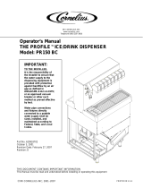
Cleaning Dispensing Valve
1. Remove nozzle assembly (contains Inner Nozzle) from dispensing valve. Separate the inner nozzle
from the nozzle and wash the two parts in warm water.
2. Remove the bottom plate by releasing the two snap-fit clips. Remove the lever from the bottom
plate and wash the bottom plate and the lever in warm water.
3. Reassemble the lever into the bottom plate and return the bottom plate to the valve. Be sure the
rear tabs are properly secured.
4. Return the inner nozzle to the nozzle and replace the assembly to the valve.
BOTTOM
PLATE P/N
1903
O
F
F
SNAP FIT CLIP
REAR
TAB
SNAP FIT
CLIP
INNER
NOZZLE
NOZZLE
SNAP FIT
CLIP
SNAP FIT
CLIP

IDC Operator’s Manual
Publication Number: 621057403OPR - 6 - © 2005-2009, IMI Cornelius Inc.
MAINTENANCE
The following dispenser maintenance should be performed at the intervals indicated:
DAILY (OR AS REQUIRED)
Remove foreign material from vending area drip tray to prevent drain blockage.
Clean vending area. Check for proper water drainage from the vending area drip tray.
Checking CO
2
Supply
Make sure CO
2
cylinder regulator assembly 1800-psi gage indicator is not in shaded (“change CO
2
cylinder”) portion of the dial. If so, the CO
2
cylinder is almost empty and must be replaced.
Checking for CO
2
and water leak
Check the Unit for CO
2
and water leaks and if found, call a qualified Service Person to repair as
necessary.
MONTHLY
Clean and sanitize the hopper interior and beverage system, if applicable (see CLEANING
INSTRUCTIONS).
YEARLY
Water Pump Maintenance (or after water system disruption)
The water pump water strainer screen and the liquid dual check valve must be inspected and cleaned at
least once a year under normal circumstances and after any water system disruption (plumbing work,
earthquake, etc.). Call a qualified Service Person to inspect and clean the strainer screen and the liquid
dual check valve.
Cleaning CO
2
Gas Check Valve
The CO
2
gas check valve, located on the carbonated water tank, must be inspected and serviced at least
once a year under normal conditions and after any CO
2
system servicing disruption. Call a qualified
Service Person to inspect and clean the CO
2
gas check valve.
NOTE: If the power cord is damaged, it must be replaced by the manufacturer, its service agent
or similar qualified persons in order to avoid a hazardous situation.

IDC Operator’s Manual
© 2005-2009, IMI Cornelius Inc. - 7 - Publication Number: 621057403OPR

IMI Cornelius Inc.
www.cornelius.com
/