
RELEASE
BR-C050-IM-F
JAPAN
GREASE
15-20Nm
BR-C050-IM-F
RELEASE
Cable adjusting bolt
JAPAN
GREASE
15-20Nm
BR-C050-IM-F
RELEASE
Cable adjusting nut
Tightening torque:
1 – 2 N·m
{9 – 17 in. lbs.}
After depressing the brake lever to check the
braking performance, secure the cable adjusting
bolt with the cable adjusting nut.
3.
JAPAN
GREASE
15-20Nm
BR-C050-IM-F
RELEASE
JAPAN
GREASE
15-20Nm
BR-C050-IM-F
RELEASE
RELEASE
BR-C050-IM-F
RELEASE
JAPAN
GREASE
15-20Nm
BR-C050-IM-F
RELEASE
JAPAN
GREASE
15-20Nm
BR-C050-IM-F
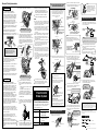
Hole in the inner
cable fixing bolt
Outer casing holder
Should be
20 – 22 mm
Note:
When installing the link unit to the cam
transmission plate, push the link unit in until it
clicks, and check that it is securely in the position
shown in the illustration.
RELEASE
GREASE
BR-C050-IM-F
RELEASE
GREASE
BR-C050-IM-F
2
3
Link unit
Link unit
3
Pull down
strongly
The rivet should fit in the center
of section A of the cam
transmission plate.
1
2
Slide sideways
Guide groove
Link unit
While pushing the
cam transmission
plate upward
Guide groove
RELEASE
JAPAN
GREASE
15-20Nm
BR-C050-IM-F
Touching
1 mm
or more
Hub nut
Hub axle
Brazed-on
bracket
RELEASE
JAPAN
GREASE
15-20Nm
BR-C050-IM-F
Front brake unit
Brake unit fixing nut
V
C R
C R
V
Check that both ends of the outer casing are
securely inserted into the cable adjusting bolts of
both the brake lever and brake arm.
Cable adjusting bolt
SI-75N0B
When using the Shimano Inter-M brake system,
avoid continuous application of the brakes when
riding down long slopes, as this will cause the
internal brake parts to become very hot, and this
may weaken braking performance. It may also
cause a reduction in the amount of brake grease
inside the brake, and this can lead to problems
such as abnormally sudden braking.
The design of the Shimano Inter-M brake system
has been carried out based on standards such as
ISO 4210 and DIN 79100-2. These standards
specify the performance for an overall weight of
100 kg. If the overall weight exceeds 100 kg, the
braking force provided by the system may be
insufficient for correct braking, and durability of the
system may also be reduced.
If any of the following occur while using the
brakes, stop riding immediately and ask the
place of purchase to carry out inspection and
repairs.
1) If abnormal noise is heard when the brakes
are applied
2) If braking force is abnormally strong
3) If braking force is abnormally weak
In the case of 1) and 2), the cause might be not
enough brake grease, so ask the place of
purchase to grease the mechanism with special
roller brake grease.
If the brakes are used frequently, the brake drum
may become hot. Do not touch the brake drum
for at least 30 minutes after you finish riding the
bicycle.
The BR-C050-IM-F front brake unit and HB-C052-
IM / HB-C050-DR / HB-C051-DR front hub unit
should never be disassembled. If they are
disassembled, malfunctions and damage to the
front brake unit and front hub unit could result.
Consult the place of purchase for details on
removing and installing the front brake unit.
CAUTION
Front Inter-M
Brake System
NOTE:
The front Inter-M brake system should only be
installed to the left side of a bicycle which is 26" or
larger. If it is used on a bicycle which is smaller
than 26", the braking force may be too great, which
could cause accidents.
Use a wheel with 3x or 4x spoke lacing. Wheels with
radial lacing cannot be used because the spokes and
the wheel can be damaged when applying the brakes
and brake noise can be generated.
The front Inter-M brake is different from conventional
band brakes in that the inside of the brake drum is
filled with grease. This may cause the turning of the
wheel to be slightly heavier than usual, particularly in
cold weather.
The front Inter-M brake has a built-in power modulator
which controls the braking force applied to the hub.
Noise is generated by the operation of the power
modulator when the brake is applied, but this is not a
sign of a malfunction.
If you apply the front Inter-M brake strongly while the
bicycle is stopped and then shake the wheel, you will
notice that there is a small amount of play in the
brakes. This is normal, and will not cause any
problems at all while riding.
To check tha amount of looseness in the head parts,
grasp the middle of the handlebar and one of the front
forks as shown in the illustration, and then move the
head parts back and forth in the directions indicated
by the arrows.
Moreover, because the brakes give a small amount of
play if you apply the brakes fully and shake the wheel
as described above, this will make it more difficult to
check the looseness
in the head parts.
In order to realize the best performance from the Shimano
front Inter-M brake system, we recommend that the
following combination be used.
Use the BR-C050-IM-F front brake unit in conjunction with a
nut-type hub.
*
Tightening torque:
30 – 45 N·m {260 – 390 in. lbs.}
Tightening torque:
15 – 20 N·m {130 – 174 in. lbs.}
Brake drum
To install the brake cable again, carry out the
above procedure in reverse.
When installing the link unit to the cam
transmission plate, push the link unit in until
it clicks, and check that it is securely in the
position shown in the illustration.
Depress the brake lever to check the braking
performance. If the braking performance is
poor, adjust the brake cable once more while
referring to "Adjusting the brake cable".
Note:
Disconnecting the brake cable
from the front brake unit
Push the cam transmission plate until it stops.
Then, slide the link unit along the guide groove
in the cam transmission plate to remove the
link unit. If the link unit is difficult to remove,
turn the cable adjusting bolt clockwise to
release the cable tension first.
It is important to completely understand the
operation of your bicycle's brake system. Improper
use of your bicycle's brake system may result in a
loss of control or an accident, which could lead to
severe injury. Because each bicycle may handle
differently, be sure to learn the proper braking
technique (including brake lever pressure and
bicycle control characteristics) and operation of your
bicycle. This can be done by consulting your
professional bicycle dealer and the bicycle's owners
manual, and by practicing your riding and braking
technique.
The ST-EF29 (
4-finger
) / SB-C055 (
4-finger
) / ST-
C050 brake levers are equipped with a mode
switching mechanism. Be sure to use the BR-C050-
IM-F with the mechanism in the C.R mode position.
Obtain and read the service instructions carefully
prior to installing the parts. Loose, worn, or damaged
parts may cause serious injury to the rider.
We strongly recommend only using genuine
Shimano replacement parts.
The C indicates the mode position for
compatibility with cantilever brakes.
The R indicates the mode position for
compatibility with roller brakes.
WARNING
C.R mode position
Check that the front brake unit is firmly secured to
the hub body with the brake unit fixing nut.
Check that the hub axle is touching the back of the
fork end, and that the end of the brake arm is
protruding 1 mm or more from the brazed-on
bracket of the front fork. Check also that the wheel
is firmly secured to the frame with the hub nut. If
the wheel is not installed properly, it may come off
the frame, which could result in serious accidents
when riding.
For maximum performance we highly recommend
Shimano lubricants and maintenance products.
Parts are not guaranteed against natural wear or
deterioration resulting from normal use.
15 mm of play
Turn the cable adjusting bolt of the brake unit or
brake lever so that there is about 15 mm of play in
the brake lever.
The amount of brake lever play is the distance
from the position where the brake lever is not
operated to the position where a force is felt
suddenly when the brake lever is pulled.
In order to get the best performance from the
Shimano front Inter-M brake, be sure to use
Shimano brakes cables and brake levers as a set.
(Refer to the product line-up.)
The amount of movement of the inner cable
must be 14.5 mm or more when the brake lever
is depressed. If it is less than 14.5 mm, braking
performance will suffer, and the brakes may fail
to work.
Always make sure that the front and rear brakes are
working correctly before you ride the bicycle.
Read these Technical Service Instructions carefully,
and keep them in a safe place for later reference.
If the road surface is wet, the tires will skid more
easily. If the tires skid, you may fall off the bicycle.
To avoid this, reduce your speed and apply the
brakes early and gently.
Sep. 2004 by Shimano Inc. PIT. SZK. Printed in Japan
C
General Safety Information
Technical Service Instructions
– To avoid serious injuries:
– To avoid serious injuries:
BR-C050-IM-F
HB-C052-IM
HB-C050-DR
HB-C051-DR
ST-EF29
(
4-finger
)
SB-C055
(
4-finger
)
ST-C050
Brake
Hub
Lever
Brake cable
If the brake cable becomes rusted, braking
performance will suffer. If this happens, replace
the brake cable with a genuine Shimano brake
cable and re-check the braking performance.
RELEASE
BR-C050-IM-F
Section A of cam
transmission plate
Link unit rivet
The rivet should fit
in the center of
section A of the cam
transmission plate.
Section A of cam transmission plate
Link unit rivet
JAPAN
Brake arm
Guide slot
Outer casing holder
Cable adjusting bolt
JAPAN
Brake arm
Guide slot
Outer casing holder
Cable adjusting bolt
Cable adjusting bolt
Slide the outer casing holder along the guide
slot in the brake arm to remove it from the slot.
Slide strongly along the guide
groove as far as possible
Cable adjusting bolt
Guide groove
Hold the cam transmission plate with your hand,
and slide the link unit along the guide groove in the
cam transmission plate to install the link unit.
Guide groove
While holding the
cam transmission
plate
Place the cable adjusting bolt so that it is 20 – 22
mm from the end of the outer casing holder, and
then pass the inner cable through the cable
adjusting bolt and then through the hole in the inner
cable fixing bolt.
JAPAN
GREASE
15-20Nm
BR-C050-IM-F
RELEASE
Inner cable fixing nut
Pull strongly
Tighten
While pushing the cam
transmission plate
3
1
2
Tightening torque:
6 – 8 N·m
{52 – 69 in. lbs.}
Push the cam transmission plate back until it stops.
Then, while pulling the inner cable to apply the full
amount of tension to the cable, tighten the inner
cable fixing nut.
Place into the
guide groove
Adjusting the brake cable
After checking that the wheel does not easily turn
while the brake cable is being pulled, depress the
brake lever about 10 times as far as the grip in order
to run in the brake cable.
Depress about
10 times
Note:
If the brake cable is not run in, it will need to be
adjusted again after only a short period of use.
Both ends of the outer casing
should be securely inserted.
1
RELEASE
After tightening the inner cable
fixing nut, attach the inner end
cap to the end of the inner cable.
Then set the inner end cap so
that it does not touch the link
and the spokes.
Note:
These service instructions explain how to use and maintain the
Shimano bicycle parts which have been used on your new
bicycle. For any questions regarding your bicycle or other
matters which are not related to Shimano parts‚ please contact
the place of purchase or the bicycle manufacturer.
These service instructions are printed on recycled paper.
Please note: Specifications are subject to change for improvement without
notice. (English)
Link unit
Slide the outer casing holder along the guide slot in
the brake arm to set it into the slot.
Installing the brake cable
1.
2.
3.
8.
7.
6.
5.
4.
9.
1.
2.
1.
2.
3.
4.
5.
2.
1.
10.
One Holland, Irvine, California 92618, U.S.A. Phone: +1-949-951-5003
Industrieweg 24, 8071 CT Nunspeet, The Netherlands Phone: +31-341-272222
3-77 Oimatsu-cho, Sakai, Osaka 590-8577, Japan
JAPAN
-
 1
1

Shimano ST-C050 Service Instructions
- Category
- Bicycles
- Type
- Service Instructions
Ask a question and I''ll find the answer in the document
Finding information in a document is now easier with AI
Related papers
-
Shimano FD-M950 Service Instructions
-
Shimano BR-IM75 Service Instructions
-
Shimano BR-IM73 Service Instructions
-
Shimano FH-R500 Service Instructions
-
Shimano ST-MC12 Service Instructions
-
Shimano BR-IM35-RF User manual
-
Shimano BR-IM70 Service Instructions
-
Shimano BR-IM77 Service Instructions
-
Shimano FH-E700 Service Instructions
-
Shimano BR-IM50 Service Instructions