Page is loading ...

W 1 6 4 N 9 2 2 1 Wa t er St r e et • P.O. Box 450 • Menomonee Falls, Wisconsin 53052-0450 USA
PHONE: 262.251.3800 • 800.558.8744
USA/CANADA FAX: 262.251.7067 • 800.329.8744 U.S.A. ONLY
WEBSITE: www.alto-shaam.com
P R I N TE D I N U .S .A .
®
H o t F o o d D r o p - I n W e l l s
E l e c t r i c
Models:
100-HW
200-HW
300-HW
400-HW
500-HW
• INSTALLATION
• OPERATION
• MAINTENANCE
#808 - 2/07
100-HW
p
ans not included
300-HW

DELIVERY
This Alto-Shaam appliance has been
thoroughly tested and inspected to insure only the
highest quality unit is provided. Upon receipt,
check for any possible shipping damage and
report it at once to the delivering carrier. See
Transportation Damage and Claims section
located in this manual.
This appliance, complete with unattached
items and accessories, may have been delivered in
one or more packages. Check to ensure that all
standard items and options have been received
with each model as ordered.
Save all the information and instructions
packed with the appliance. Complete and return
the warranty card to the factory as soon as
possible to assure prompt service in the event of a
warranty parts and labor claim.
This manual must be read and understood by
all people using or installing the equipment
model. Contact the Alto-Shaam service
department if you have any questions concerning
installation, operation, or maintenance.
NOTE: All claims for warranty must include the
full model number and serial number of
the unit.
UNPACKING
1
. Carefully remove the
appliance from the
carton or crate.
NOTE: Do not discard the
carton and other
packaging material
until you have
inspected the unit
for hidden damage
and tested it for
proper operation.
2. Read all instructions in this manual carefully
before initiating the installation of this appliance.
DO NOT DISCARD THIS MANUAL.
This manual is considered to be part of the
appliance and is to be provided to the owner
or manager of the business or to the person
responsible for training operators. Additional
manuals are available from the Alto-Shaam
service department.
3. Remove all protective plastic film, packaging
materials, and accessories from the appliance
before connecting electrical power. Store any
accessories in a convenient place for future use.
®
®
®
#808 Ho t fo o d Dro p -In We ll
• 1.

#808 Ho t fo o d Dro p -In We ll
• 2.
SAFETY PROCEDURES
AND PRECAUTIONS
Knowledge of proper procedures is essential to the
safe operation of electrically and/or gas energized
equipment. In accordance with generally accepted
product safety labeling guidelines for potential
hazards, the following signal words and symbols
may be used throughout this manual.
Used to indicate the
presence of a hazard that
will cause severe personal
injury, death, or substantial
property damage if the
warning included with this
symbol is ignored.
Used to indicate the
presence of a hazard that
can
cause personal injury,
possible death, or major
property damage if the
warning included with this
symbol is ignored.
Used to indicate the
presence of a hazard that
can or will cause minor or
moderate personal injury
or property damage if the
warning included with this
symbol is ignored.
Used to indicate the
presence of a hazard that
can or will cause minor
personal injury, property
damage, or a potential
unsafe practice if the
warning included with this
symbol is ignored.
Used to notify personnel of
installation, operation, or
maintenance information that is
important but not hazard related.
1. This appliance is intended to cook, hold or
process foods for the purpose of human
consumption. No other use for this
appliance is authorized or recommended.
2. This appliance is intended for use in
commercial establishments where all
operators are familiar with the purpose,
limitations, and associated hazards of this
appliance. Operating instructions and
warnings must be read and understood by
all operators and users.
3. Any troubleshooting guides, component
views, and parts lists included in this manual
are for general reference only and are intended
for use by qualified technical personnel.
4. This manual should be considered a
permanent part of this appliance. This
manual and all supplied instructions,
diagrams, schematics, parts lists, notices, and
labels must remain with the appliance if the
item is sold or moved to another location.
NOTE:

#808 Ho t fo o d Dro p -In We ll
• 3.
OPTIONS AND ACCESSO RIE S
PAN DIVIDER BARS
• FULL-SIZE 16019
• H
ALF-SIZE / THIRD-SIZE 11318
S I T E I N S TA L L AT I O N
The Alto-Shaam
appliance must be
installed in a location
that will permit the
unit to function for its
intended purpose and
to allow for proper
cleaning, and
maintenance.
1. The appliance must be installed on a stable
and level surface. A non-combustible, heat
resistant surface is highly recommended.
2. DO NOT install this appliance in any area
where it may be affected by any adverse
conditions such as steam, grease, dripping
water, high temperatures, etc.
LEVELING
The heated well
should be leveled
before the electrical supply is
connected. Level the appliance from side-to-side
and front-to-back with the use of a spirit level.
For appliances installed on a mobile stand, it is
important that the floor surface be level due to
the probability of frequent repositioning.
NOTE
It is important to apply a food grade silicone
underneath the decor flange to seal flange to the
countertop.
®
ROUGH CUT COUNTE R TOP OPEN ING
MODEL 100-HW ONE PAN: 22-3/8" x 14-1/4" (568mm x 362mm)
MODEL 200-HW TWO PAN: 22-3/8" x 27-1/8" (568mm x 689mm)
MODEL 300-HW THREE PAN: 22-3/8" x 40-1/8" (568mm x 1019mm)
MODEL 400-HW FOUR PAN: 22-3/8" x 53-1/4" (568mm x 1353mm)
MODEL 500-HW FIVE PAN: 22-3/8" x 66-1/4" (568mm x 1683mm)
TO PREVENT PERSONAL INJURY,
U
SE CAUTION WHEN MOVING OR
LEVELING THIS APPLIANCE.

1. An identification tag is permanently mounted
on the appliance.
2. This appliance is equipped with a three-prong
grounding plug. For your protection against
shock hazard this appliance should be plugged
directly into a properly grounded three-prong
receptacle. Do not cut or remove the grounding
prong from this plug. Plug the unit into a
properly grounded receptacle ONLY, positioning
the unit so that the plug is easily accessible in
case of an emergency. Arcing will occur when
connecting or disconnecting the unit unless all
controls are in the “OFF” position.
3. Proper receptacle or outlet configuration or
permanent wiring for this unit must be
installed by a licensed electrician in
accordance with applicable local
electrical codes.
4. For 230V units:
To prevent an electrical shock hazard between the
appliance and other appliances or metal parts in
close vicinity, an equalization-bonding stud is
provided. An equalization bonding lead must be
connected to this stud and the other appliances /
metal parts to provide sufficient protection
against potential difference. The terminal is
marked with the following symbol.
NOTE: The appliance must be connected to an
electrical circuit that is protected by an external
GFCI outlet.
E L E C T R I C A L C O N N E C T I O N
I N S TA L L AT I O N
#808 Ho t fo o d Dro p -In We ll
• 4.
ELECTRICAL CONNECTIONS MUST
BE MADE BY A QUALIFIED SERVICE
TECHNICIAN IN ACCORDANCE WITH
APPLICABLE ELECTRICAL CODES.
To avoid electrical shock, this
appliance MUST be adequately
grounded in accordance with local
electrical codes or, in the absence of
local codes, with the current edition
of the National Electrical Code
ANSI/NFPA No. 70. In Canada, all
electrical connections are to be made
in accordance with CSA C22.1,
Canadian Electrical Code Part 1 or
local codes.

#808 Ho t fo o d Dro p -In We ll
• 5.
E L E C T R I C A L S P E C I F I C AT I O N S
I N S TA L L AT I O N
E L E C T R I C A L • 2 0 0 - H W
VOLTAGE PHASE CYCLE/ HZ AMPS kW PLUG CONFIGURATION
120 1 60 10.5 1.27 NEMA 5-15P 15A-125V PLUG
at 208 1 50/60 4.5 .95
at 240 1 50/60 5.2 1.27
NEMA 6-15P 15A-250V PLUG
230 1 50/60 5.0 1.17 BS 1363 PLUG (UK ONLY)
208-240
E L E C T R I C A L • 1 0 0 - H W
VOLTAGE PHASE CYCLE/ HZ AMPS k
W PLUG CONFIGURATION
1
20 1 60 4.8 .58
NEMA 5
-15
P 1
5
A-
125
V PLUG
E L E C T R I C A L • 3 0 0 - H W
VOLTAGE PHASE CYCLE/ HZ AMPS kW PLUG CONFIGURATION
120 1 60 19.6 2.35 NEMA L5-30P 30A-125V PLUG
at 208 1 50/60 9.2 1.93
at 240 1 50/60 10.7 2.57
NEMA 6-15P 15A-250V PLUG
230 1 50/60 10.2 2.36 BS 1363 PLUG (UK ONLY)
208-240
E L E C T R I C A L • 4 0 0 - H W
VOLTAGE PHASE CYCLE/ HZ AMPS kW PLUG CONFIGURATION
120 1 60 19.6 2.36 NEMA L5-30P 30A-125V PLUG
at 208 1 50/60 8.5 1.77
at 240 1 50/60 9.9 2.38
NEMA 6-15P 15A-250V PLUG
230 1 50/60 9.5 2.19 BS 1363 PLUG (UK ONLY)
208-240
E L E C T R I C A L • 5 0 0 - H W
VOLTAGE PHASE CYCLE/ HZ AMPS kW PLUG CONFIGURATION
120 1 60 19.9 2.39 NEMA L5-30P 30A-125V PLUG
at 208 1 50/60 8.6 1.80
at 240 1 50/60 9.9 2.39
NEMA 6-15P 15A-250V PLUG
230 1 50/60 9.5 2.20 BS 1363 PLUG (UK ONLY)
208-240

#808 Ho t fo o d Dro p -In We ll
• 6.
.
I N S TA L L AT I O N
M O U N T I N G I N S T R U C T I O N S • R E M O T E C O N T R O L H O U S I N G
1. Cut a 5-1/4" x 4-1/4" (c. 133,4mm x 108mm) opening in the location where each control is to be positioned.
2. Thoroughly clean and dry the mounting surface around the control cut-out opening on which the decor face will be
applied.
NOTE: The control face will not properly adhere to an unclean surface.
3. Remove the protective film from the mounting tape on the inside flanges of the decor face and apply the decor face
to the mounting surface.
4. Position the remote control housing behind the decor face. Use the two (2) mounting screws through the thermostat
bezel of the decor face to fasten the decor face to the control housing.
5. Insert the thermostat knob onto the thermostat shaft.
Apply a food grade silicone
along the outside edge of
the hot well support flange.
PAN DIVIDER
BARS #16019
FLEXIBLE WATER-
TIGHT TETHER
B
DECOR FACE
BEZEL
THERMOSTAT KNOB
MOUNTING
SCREWS
B

Electrical Cord
60" (1524mm)
One (1) flexible
water-tight tether
30" (762mm)
14"
(355mm)
5-3/16"
(132mm)
5-5/16"
(136mm)
Control
1
6-1/8"
(409mm)
24-1/8"
(613mm)
7-9/16"
(193mm)
7-9/16"
(193mm)
22"
(558mm)
4-3/16" (106mm)
One (1) flexible
water-tight tether
30" (762mm)
26-5/8" (677mm)
5-3/16"
(132mm)
5-5/16"
(136mm)
Control
28-15/16"
(
734mm)
24-1/8"
(613mm)
7-9/16"
(193mm)
7-9/16"
(
193mm)
22"
(558mm)
4-3/16" (106mm)
Removable Divider Bar
#16019
E
lectrical Cord
60" (1524mm)
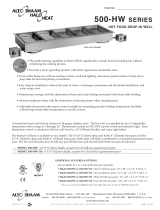
I N S TA L L AT I O N
D I M E N S I O N S • C A PA C I T Y
10 0 - H W 20 0 - H W
P R O D U C T \ PA N C A PA C I T Y
12 lb (5.4 kg)
MAXIMUM
MAX. VOLUME: 7.5 QUARTS (9.5 LITERS)
FULL-SIZE PANS*:
One (1) 12" x 20" x 2-1/2"
GN 1/1 (325mm x 530mm x 65mm)
HALF-SIZE PANS*:
Two (2) 12" x 10" x 2-1/2"
GN 1/2 (325mm x 265mm x 65mm)
THIRD-SIZE PANS*:
Three (3) 12" x 6" x 2-1/2"
GN 1/3 (325mm x 176mm x 65mm)
*W I L L A L S O A C C E P T 4" (1 0 0 mm ) D E EP PA NS
P R O D U C T \ PA N C A PA C I T Y
24 lb (10.8 kg)
MAXIMUM
MAX. VOLUME: 15 QUARTS (19 LITERS)
FULL-SIZE PANS*:
Two (2) 12" x 20" x 2-1/2"
GN 1/1 (325mm x 530mm x 65mm)
HALF-SIZE PANS*:
Four (4) 12" x 10" x 2-1/2"
GN 1/2 (325mm x 265mm x 65mm)
THIRD-SIZE PANS*:
Six (6) 12" x 6" x 2-1/2"
GN 1/3 (325mm x 176mm x 65mm)
*W I L L A L S O A C C E P T 4" (1 0 0 mm ) D E EP PA NS
#808 Ho t fo o d Dro p -In We ll
• 7.

I N S TA L L AT I O N
One (1) flexible
w
ater-tight tether
30" (762mm)
39-11/16" (1007mm)
5-3/16"
(132mm)
5-5/16"
(136mm)
Control
4
2" (1066mm)
24-1/8"
(613mm)
7
-9/16"
(193mm)
7-9/16"
(193mm)
22"
(558mm)
4-3/16" (106mm)
Removable Divider Bars
#16019 #11318
Electrical Cord
60" (1524mm)
Two flexible
water-tight tethers
30" each (762mm)
52-3/4" (1339mm)
5-3/16"
(132mm)
5-5/16"
(136mm)
Controls
55" (1398mm)
24-1/8"
(613mm)
7-9/16"
(193mm)
22"
(558mm)
4-3/16" (106mm)
Removable
Divider Bars #16019
7-9/16"
(193mm)
Electrical Cord
60" (1524mm)
D I M E N S I O N S • C A PA C I T Y
3
00 - H W
40 0 - H W
#808 Ho t fo o d Dro p -In We ll
• 8.
P R O D U C T \ PA N C A PA C I T Y
36 lb (16 kg)
MAXIMUM
MAX. VOLUME: 22.5 QUARTS (28.5 LITERS)
FULL-SIZE PANS*:
Three (3) 12" x 20" x 2-1/2"
GN 1/1 (325mm x 530mm x 65mm)
HALF-SIZE PANS*:
Six (6) 12" x 10" x 2-1/2"
GN 1/2 (325mm x 265mm x 65mm)
THIRD-SIZE PANS*:
Nine (9) 12" x 6" x 2-1/2"
GN 1/3 (325mm x 176mm x 65mm)
*W I L L A L S O A C C E P T 4" (1 0 0 mm ) D E EP PA NS
P R O D U C T \ PA N C A PA C I T Y
48 lb (22 kg)
MAXIMUM
MAX. VOLUME: 30 QUARTS (38 LITERS)
FULL-SIZE PANS*:
Four (4) 12" x 20" x 2-1/2"
GN 1/1 (325mm x 530mm x 65mm)
HALF-SIZE PANS*:
Eight (8) 12" x 10" x 2-1/2"
GN 1/2 (325mm x 265mm x 65mm)
THIRD-SIZE PANS*:
Twelve (12) 12" x 6" x 2-1/2"
GN 1/3 (325mm x 176mm x 65mm)
*W I L L A L S O A C C E P T 4" (1 0 0 mm ) D E EP PA NS

Two flexible
water-tight tethers
36" each (914mm)
65-3/4" (1670mm)
5-3/16"
(132mm)
5-5/16"
(136mm)
Controls
68-1/8" (1730mm)
24-1/8"
(613mm)
7-9/16"
(193mm)
22"
(558mm)
4-3/16" (106mm)
Removable
Divider Bars #16019
7-9/16"
(193mm)
Electrical Cord
60" (1524mm)
D I M E N S I O N S * C A PA C I T Y
50 0 - H W
I N S TA L L AT I O N
#808 Ho t fo o d Dro p -In We ll
• 9.
P R O D U C T \ PA N C A PA C I T Y
60 lb (27 kg)
MAXIMUM
MAX. VOLUME: 37.5 QUARTS (47.5 LITERS)
FULL-SIZE PANS*:
Five (5) 12" x 20" x 2-1/2"
GN 1/1 (325mm x 530mm x 65mm)
HALF-SIZE PANS*:
Ten (10) 12" x 10" x 2-1/2"
GN 1/2 (325mm x 265mm x 65mm)
THIRD-SIZE PANS*:
Fifteen (15) 12" x 6" x 2-1/2"
GN 1/3 (325mm x 176mm x 65mm)
*W I L L A L S O A C C E P T 4" (1 0 0 mm ) D E EP PA NS

OPERATION
1. DO NOT ADD WATER TO HOT WELL
Halo Heat® hot wells maintain a constant and
gentle temperature. Adding water is not
recommended since water will accelerate the
deterioration of the product and may damage the
unit voiding the warranty.
2. PLACE PAN DIVIDERS AND EMPTY PANS
IN THE WELLS
NOTE: No matter what type of pan configuration
chosen, pan separator bars or divider bars must
be used to close all gaps between pans, and all
gaps between the pans and the edges of the wells.
If these gaps are not closed, heat will escape, heat
distribution will be uneven, and uniform
temperature will be difficult to maintain.
This is a VERY important requirement to follow
whenever this appliance is in use.
3. PREHEAT AT THE NUMBER “10” SETTING
FOR A MINIMUM OF 30 MINUTES
An indicator light will illuminate when the
thermostat(s) is (are) turned “ON.”
The indicator(s) will remain lit as
long as the unit is preheating or
calling for heat. The unit should
be preheated at the 10 setting for a
minimum of 30 minutes before
loading the unit with hot food. When preheating
is completed, or whenever the unit reaches any
temperature set by the operator between 1 and 10,
the indicator light(s) will go “OUT”.
4. LOAD HOT FOODS INTO THE APPLIANCE
After preheating, place hot foods into the
preheated pans located in the appliance or
exchange the pans with pre-filled product pans.
This appliance is designed for the purpose of hot
food holding. Only hot foods should be placed
into the unit. All pan divider bars required must
be utilized at all times with the pan configuration
chosen. Before loading food into the unit, use a
pocket-type thermometer to make certain all
products have reached an internal temperature of
140° to 180° F (60° to 82°C). If any food product is
not at proper serving temperature, use a Halo Heat
cooking and holding oven, set at 250° to 275°F (121°
to 135°C), or a Combitherm oven to bring the
product within the correct temperature range.
5. RESET THERMOSTAT(S) AS NEEDED
After all products are loaded into the unit, it is
necessary to reset the thermostat(s). Since proper
temperature range depends on
the type of products and the
quantities being held, it is
necessary to periodically use a
pocket thermometer to check each
item to make certain the correct temperatures are
being maintained. Proper temperature range is
between a minimum of 140° and 180° F (60° and
82° C). Normally, this will require a thermostat
setting of between number “8” and “10.”
6. SERVE FRESH HOT FOOD
Keep hot foods looking fresh. Occasionally stir or
rotate food as needed. Wipe spills immediately to
assure maximum eye appeal and to ease end of
the day cleanup.
1
0
9
8
7
6
5
4
3
2
1
1
0
9
8
7
6
5
4
3
2
1
METAL PARTS OF THIS EQUIPMENT
BECOME EXTREMELY HOT WHEN IN
OPERATION. TO AVOID BURNS,
ALWAYS USE HAND PROTECTION
WHEN OPERATING THIS APPLIANCE.
#808 Ho t fo o d Dro p -In We ll
• 10.

GENERAL HOLDING GUIDELINES
Chefs, cooks and other specialized food service
personnel employ varied methods of cooking. Proper
holding temperatures for a specific food product must
be based on the moisture content of the product,
product density, volume, and proper serving
temperatures. Safe holding temperatures must also be
correlated with palatability in determining the length
of holding time for a specific product.
Halo Heat maintains the maximum amount of product
moisture content without the addition of water, water
vapor, or steam. Maintaining maximum natural
product moisture preserves the natural flavor of the
product and provides a more genuine taste. In
addition to product moisture retention, the gentle
properties of Halo Heat maintain a consistent
temperature throughout the cabinet without the
necessity of a heat distribution fan, thereby preventing
further moisture loss due to evaporation or
dehydration.
When product is removed from a high temperature
cooking environment for immediate transfer into
equipment with the lower temperature required for hot
food holding, condensation can form on the outside of
the product and on the inside of plastic containers used
in self-service applications. Allowing the product to
release the initial steam and heat produced by high
temperature cooking can alleviate this condition. To
preserve the safety and quality of freshly cooked foods
however, a maximum of 1 to 2 minutes must be the
only time period allowed for the initial heat to be
released from the product.
Most Halo Heat holding equipment is provided with a
thermostat control between 60° and 200°F (16° to 93°C).
If the unit is equipped with vents, close the vents for
moist holding and open the vents for crisp holding.
If the unit is equipped with a thermostat indicating a
range of between 1 and 10, use a metal-stemmed
indicating thermometer to measure the internal
temperature of the product(s) being held. Adjust the
thermostat setting to achieve the best overall setting
based on internal product temperature.
H O L D I N G T E M P E R A T U R E R A N G E
MEAT FA H R EN H E IT CE L S IU S
B
EEF ROAST — Rare 140°F 60°C
BEEF ROAST — Med/Well Done 160°F 71°C
BEEF BRISKET 160° — 175°F 71° — 79°C
C
ORN BEEF 160° — 175°F 71° — 79°C
PASTRAMI 160° — 175°F 71° — 79°C
PRIME RIB — Rare 140°F 60°C
S
TEAKS — Broiled/Fried 140° — 160°F 60° — 71°C
RIBS — Beef or Pork 160°F 71°C
VEAL 160° — 175°F 71° — 79°C
H
AM 160° — 175°F 71° — 79°C
PORK 160° — 175°F 71° — 79°C
LAMB 160° — 175°F 71° — 79°C
P
OULTRY
CHICKEN — Fried/Baked 160° — 175°F 71° — 79°C
DUCK 160° — 175°F 71° — 79°C
T
URKEY 160° — 175°F 71° — 79°C
GENERAL 160° — 175°F 71° — 79°C
FISH/SEAFOOD
F
ISH — Baked/Fried 160° — 175°F 71° — 79°C
LOBSTER 160° — 175°F 71° — 79°C
SHRIMP — Fried 160° — 175°F 71° — 79°C
B
AKED GOODS
BREADS/ROLLS 120° — 140°F 49° — 60°C
MISCELLANEOUS
C
ASSEROLES 160° — 175°F 71° — 79°C
DOUGH — Proofing 80° — 100°F 27° — 38°C
EGGS —Fried 150° — 160°F 66° — 71°C
FROZEN ENTREES 160° — 175°F 71° — 79°C
HORS D'OEUVRES 160° — 180°F 71° — 82°C
PASTA 160° — 180°F 71° — 82°C
PIZZA 160° — 180°F 71° — 82°C
POTATOES 180°F 82°C
PLATED MEALS 180°F 82°C
SAUCES 140° — 200°F 60° — 93°C
SOUP 140° — 200°F 60° — 93°C
VEGETABLES 160° — 175°F 71° — 79°C
The holding temperatures listed are suggested guidelines only.
#808 Ho t fo o d Dro p -In We ll
• 11.

CARE AND CLEANING
PROTECTING STAINLESS STEEL SURFACES
I
t is important to guard against
c
orrosion in the care of
stainless steel surfaces.
Harsh, corrosive, or
inappropriate chemicals can
completely destroy the
protective surface layer of stainless steel. Abrasive
pads, steel wool, or metal implements will abrade
surfaces causing damage to this protective coating
and will eventually result in areas of corrosion.
Even water, particularly hard water that contains
high to moderate concentrations of chloride, will
cause oxidation and pitting that result in rust and
corrosion. In addition, many acidic foods spilled
and left to remain on metal surfaces are
contributing factors that will corrode surfaces.
Proper cleaning agents, materials, and
methods are vital to maintaining the appearance
and life of this appliance. Spilled foods should be
removed and the area wiped as soon as possible
but at the very least, a minimum of once a day.
Always thoroughly rinse surfaces after using a
cleaning agent and wipe standing water as quickly
as possible after rinsing.
C
LEANING AGENTS
Use non-abrasive cleaning products designed for use
on stainless steel surfaces. Cleaning agents must be
chloride-free compounds and must not contain
quaternary salts. Never use hydrochloric acid
(muriatic acid) on stainless steel surfaces. Always use
the proper cleaning agent at the manufacturer's
recommended strength. Contact your local cleaning
supplier for product recommendations.
CLEANING MATERIALS
The cleaning function can usually be accomplished
with the proper cleaning agent and a soft, clean
cloth. When more aggressive methods must be
employed, use a non-abrasive scouring pad on
difficult areas and make certain to scrub with the
visible grain of surface metal to avoid surface
scratches. Never use wire brushes, metal scouring
pads, or scrapers to remove food residue.
CLEANING AND PREVENTIVE MAINTENANCE
#808 Ho t fo o d Dro p -In We ll
• 12.

CARE AND CLEANING
INTERIOR:
1. Disconnect appliance from the power source.
Let unit cool.
2. After the appliance has cooled, remove all
detachable items such as pans and divider bars.
Clean these items separately.
3. Remove any food scraps.
4. Wipe the interior metal surfaces with a paper
towel to remove any remaining food debris.
5. Clean interior with a damp cloth or sponge
and any good commercial detergent at the
recommended strength.
6. For baked-on food deposits, use a non-caustic
and non-toxic commercial oven cleaner
appropriate for the interior surface. Follow
the product manufacturer's instructions
carefully for the use of this product. Any
commercial oven cleaner must be approved
for use on food contact areas. Remove soil
with the use of a plastic scouring pad.
7. Rinse surfaces by wiping with a clean cloth or
sponge and clean warm water.
8. Remove excess water with a sponge and wipe
dry with a clean cloth or air dry. Leave area
open until interior is completely dry. Replace
divider bars and pans.
9. Interior can be wiped with a sanitizing
solution after cleaning and rinsing. This
solution must be approved for use on stainless
steel food contact surfaces.
DO NOT USE ABRASIVE CLEANING COMPOUNDS.
Always follow appropriate state or local health
(hygiene) regulations regarding all applicable
cleaning and sanitation requirements for food
service equipment.
NOTE: Always allow the appliance
to cool before cleaning.
CL E A N THE APP L I A N C E DAILY.
NOTE: Completely avoid the use of abrasive
cleaning compounds,
chloride-based cleaners, or
cleaners containing
quaternary salts. To protect
metal finish on stainless steel,
never use hydrochloric acid
(muriatic acid).
The cleanliness and
appearance of this
appliance will contribute
considerably to operating
e
fficiency and savory,
appetizing food. Good
equipment kept clean works
better and lasts longer.
AT NO TIME SHOULD THE INTERIOR OR
EXTERIOR BE STEAM CLEANED, HOSED
DOWN, OR FLOODED WITH WATER OR
LIQUID SOLUTION OF ANY KIND. DO NOT
U
SE WATER JET TO CLEAN.
SEVERE DAMAGE OR ELECTRICAL HAZARD
COULD RESULT.
WARRANTY BECOMES VOID IF APPLIANCE IS FLOODED.
#808 Ho t fo o d Dro p -In We ll
• 13.

#808 Ho t fo o d Dro p -In We ll
• 14.
SA NITATION
Food flavor and aroma are usually so closely related
that it is difficult, if not impossible, to separate
t
hem. There is also an important, inseparable
relationship between cleanliness and food flavor.
Cleanliness, top operating efficiency, and appearance
of equipment contribute considerably to savory,
appetizing foods. Good equipment that is kept
clean, works better and lasts longer.
Most food imparts its own particular aroma and
many foods also absorb existing odors.
Unfortunately, during this absorption, there is no
distinction between GOOD and BAD odors. The
majority of objectionable flavors and odors troubling
food service operations are caused by bacteria
growth. Sourness, rancidity, mustiness, stale or
other OFF flavors are usually the result of germ
activity.
The easiest way to insure full, natural food flavor is
through comprehensive cleanliness. This means
good control of both visible soil (dirt) and invisible
soil (germs). A thorough approach to sanitation will
provide essential cleanliness. It will assure an
attractive appearance of equipment, along with
maximum efficiency and utility. More importantly,
a good sanitation program provides one of the key
elements in the prevention of food-borne illnesses.
A controlled holding environment for prepared foods
is just one of the important factors involved in the
prevention of food-borne illnesses. Temperature
monitoring and control during receiving, storage,
preparation, and the service of foods are of equal
importance.
The most accurate method of measuring safe
temperatures of both hot and cold foods is by
internal product temperature. A quality
t
hermometer is an effective tool for this purpose,
and should be routinely used on all products that
require holding at a specific temperature.
A comprehensive sanitation program should focus
on the training of staff in basic sanitation
procedures. This includes personal hygiene, proper
handling of raw foods, cooking to a safe internal
product temperature, and the routine monitoring of
internal temperatures from receiving through
service.
Most food-borne illnesses can be prevented through
proper temperature control and a comprehensive
program of sanitation. Both these factors are
important to build quality service as the foundation
of customer satisfaction. Safe food handling
practices to prevent food-borne illness is of critical
importance to the health and safety of your
customers. HACCP, an acronym for Hazard Analysis
(at) Critical Control Points, is a quality control
program of operating procedures to assure food
integrity, quality, and safety. Taking steps necessary
to augment food safety practices are both cost
effective and relatively simple. While HACCP
guidelines go far beyond the scope of this manual,
additional information is available by contacting:
Center for Food Safety and Applied Nutrition
Food and Drug Administration
1-888-SAFEFOOD
I N T E R N A L F O O D P R OD U C T T E M P E R A T U R E S
HOT F OO D S
DANGER ZONE 40° TO 140°F (4° TO 60°C)
CRITICAL ZONE 70° TO 120°F (21° TO 49°C)
SAFE ZONE 140° TO 165°F (60° TO 74°C)
COL D FO O DS
DANGER ZONE ABOVE 40°F (ABOVE 4°C)
SAFE ZONE 36°F TO 40°F (2°C TO 4°C)
FRO ZE N FOO DS
DANGER ZONE ABOVE 32°F (ABOVE 0°C)
CRITICAL ZONE 0° TO 32°F (-18° TO 0°C)
SAFE ZONE 0°F
OR BELOW (-18°C OR BELOW)

SERVICE
THERMOSTAT and HEAT LIGHT SEQUENCE
Whenever the thermostat is turned “
10,”
the heat
i
ndicator light will indicate the power ON/OFF
condition of the heating cable, and consequently, the
cycling of the appliance as it maintains the dialed
temperature. If the light does not illuminate after
normal start-up, the main power source, thermostat,
and/or light must be checked. If the appliance does
not hold the temperature as dialed, the calibration of
the thermostat must be checked. If the appliance fails
to heat or heats continuously with the thermostat
“OFF,” the thermostat must be initially checked for
proper operation. If these items are checked and
found to be in order, a continuity and resistance
check of the heating cable should be made.
SEE CIRCUIT DIA GRA M.
SERVICE PARTS
B
K-3023 TERMINAL BLOCK, 4
BK-33546 TERMINAL BLOCK, 2
CD-3232 CORDSET, 14/3 SJTOW 125V
CD-33882 CORDSET, 230V, 16 AMP
CD-33840 CORDSET, 16/3, 250V 15A
C
D-33367 CORDSET, 12/3, 125V, 30A
KN-3473 KNOB, THERMOSTAT
LI-3027 LIGHT, INDICATOR, 25OV
LI-3951 LIGHT, INDICATOR, 110V
SW-33923 SWITCH, ROCKER
TT-33461 THERMOSTAT, FAST
TT-3713 THERMOSTAT, BEZEL
#808 Ho t fo o d Dro p -In We ll
• 15.

#808 Ho t fo o d Dro p -In We ll
• 16.

#808 Ho t fo o d Dro p -In We ll
• 17.

#808 Ho t fo o d Dro p -In We ll
• 18.

#808 Ho t fo o d Dro p -In We ll
• 19.
/