
KUPJRRW45
OPERATING MANUAL
Please read and understand this instruction manual carefully
before the installation and operation of this equipment. © Welding Guns Of Australia PTY LTD 2019

2 | RAZOR CUT 45 Manual
Thank you for your purchase of your RAZOR Plasma Cutting Machine.
We are proud of our range of plasma cutting and welding equipment that has a proven track record of innovation, performance and reliability.
Our product range represents the latest developments in Inverter technology put together by our professional team of highly skilled engineers. The
expertise gained from our long involvement with inverter technology has proven to be invaluable towards the evolution and future development of our
equipment range. This experience gives us the inside knowledge on what the arc characteristics, performance and interface between man and machine
should be.
Within our team are specialist welders that have a proven history of welding knowledge and expertise, giving vital input towards ensuring that our
machines deliver control and performance to the utmost professional level.
We employ an expert team of professional sales, marketing and technical personnel that provide us with market trends, market feedback and customer
comments and requirements. Secondly they provide a customer support service that is second to none, thus ensuring our customers have condence
that they will be well satised both now and in the future.
UNIMIG welders and plasma cutters are manufactured to be compliant with - AS/NZ 60974-1, guaranteeing you electrical safety and performance.
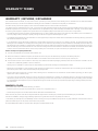
WARRANTY
• 1 Year from date of purchase.
• Welding Guns Of Australia PTY LTD Ltd warranties all goods as specied by the manufacturer of those goods.
• This Warranty does not cover freight or goods that have been interfered with.
• All goods in question must be repaired by an authorised repair agent as appointed by this company.
• Warranty does not cover abuse, misuse, accident, theft, general wear and tear.
• New product will not be supplied unless Welding Guns Of Australia PTY LTD has inspected product returned for warranty and agrees to replace product.
• Product will only be replaced if repair is not possible
• Please view full Warranty term and conditions supplied with machine or at www.unimig.com.au/warranty-registration/ or at the back of this manual.
WARNING
USE COMPRESSED AIR ONLY
WITH THIS MACHINE
WARRANTY

RAZOR CUT 45 Manual | 3
CONTENTS
WARRANTY 2
SAFETY 4
RAZOR CUT 45 - TECHNICAL DATA 7
FRONT & REAR LAYOUT 8
SET UP PROCEDURE FOR PLASMA CUTTING 9
OPERATING PROCEDURE FOR PLASMA CUTTING 10
AIR PLASMA CUTTING TECHNOLOGY 11
SC80 PLASMA TORCH 15
TROUBLE SHOOTING 16
WARRANTY TERMS 17

4 | RAZOR CUT 45 Manual
Welding and cutting equipment can be dangerous to both the operator and people in or near the surrounding working area, if the equipment is not
correctly operated. Equipment must only be used under the strict and comprehensive observance of all relevant safety regulations.
Read and understand this instruction manual carefully before the installation and operation of this equipment.
Machine Operating Safety
• Do not switch the function modes while the machine is operating. Switching of the function modes during welding can damage the
machine. Damage caused in this manner will not be covered under warranty.
• Disconnect the electrode-holder cable from the machine before switching on the machine, to avoid arcing should the electrode be in
contact with the work piece.
• Operators should be trained and or qualied.
Electric shock: It can kill. Touching live electrical parts can cause fatal shocks or severe burns. The electrode and work circuit is
electrically live whenever the output is on. The input power circuit and internal machine circuits are also live when power is on. In MIG/
MAG welding, the wire, drive rollers, wire feed housing, and all metal parts touching the welding wire are electrically live. Incorrectly
installed or improperly grounded equipment is dangerous.
• Connect the primary input cable according to Australian and New Zealand standards and regulations.
• Avoid all contact with live electrical parts of the welding/cutting circuit, electrodes and wires with bare hands.
• The operator must wear dry welding gloves while he/she performs the welding/cutting task.
• The operator should keep the work piece insulated from himself/herself.
• Keep cords dry, free of oil and grease, and protected from hot metal and sparks.
• Frequently inspect input power cable for wear and tear, replace the cable immediately if damaged, bare wiring is dangerous and can
kill.
• Do not use damaged, under sized, or badly joined cables.
• Do not drape cables over your body.
• We recommend (RCD) safety switch is used with this equipment to detect any leakage of current to earth.
Fumes and gases are dangerous. Smoke and gas generated whilst welding or cutting can be harmful to people’s health. Welding
produces fumes and gases. Breathing these fumes and gases can be hazardous to your health.
Do not breathe the smoke and gas generated whilst welding or cutting, keep your head out of the fumes
• Keep the working area well ventilated, use fume extraction or ventilation to remove welding/cutting fumes and gases.
• In conned or heavy fume environments always wear an approved air-supplied respirator.
• Welding/cutting fumes and gases can displace air and lower the oxygen level causing injury or death. Be sure the breathing air is safe.
• Do not weld/cut in locations near de-greasing, cleaning, or spraying operations. The heat and rays of the arc can react with vapours to
form highly toxic and irritating gases.
• Materials such as galvanized, lead, or cadmium plated steel, containing elements that can give off toxic fumes when welded/cut. Do
not weld/cut these materials unless the area is very well ventilated, and or wearing an air supplied respirator.
Arc rays: harmful to people’s eyes and skin. Arc rays from the welding/cutting process produce intense visible and invisible ultraviolet
and infrared rays that can burn eyes and skin.
Always wear a welding helmet with correct shade of lter lens and suitable protective clothing including welding gloves whilst the
welding/cutting operation is performed.
• Measures should be taken to protect people in or near the surrounding working area. Use protective screens or barriers to protect
others from ash,glare and sparks; warn others not to watch the arc.
SAFETY

RAZOR CUT 45 Manual | 5
Fire hazard. Welding/cutting on closed containers, such as tanks,drums, or pipes, can cause them to explode. Flying sparks from the
welding/cutting arc, hot work piece, and hot equipment can cause res and burns. Accidental contact of electrode to metal objects can
cause sparks, explosion, overheating, or re. Check and be sure the area is safe before doing any welding/cutting.
• The welding/cutting sparks & spatter may cause re, therefore remove any ammable materials well away from the working area.
Cover ammable materials and containers with approved covers if unable to be moved from the welding/cutting area.
• Do not weld/cut on closed containers such as tanks, drums, or pipes, unless they are properly prepared according to the required
Safety Standards to insure that ammable or toxic vapours and substances are totally removed, these can cause an explosion even
though the vessel has been “cleaned”. Vent hollow castings or containers before heating, cutting or welding. They may explode.
• Do not weld/cut where the atmosphere may contain ammable dust, gas, or liquid vapours (such as petrol)
• Have a re extinguisher nearby and know how to use it. Be alert that welding/cutting sparks and hot materials from welding/cutting
can easily go through small cracks and openings to adjacent areas. Be aware that welding/cutting on a ceiling, oor, bulkhead, or
partition can cause re on the hidden side.
Gas Cylinders. Shielding gas cylinders contain gas under high pressure. If damaged, a cylinder can explode. Because gas cylinders are
normally part of the welding/cutting process, be sure to treat them carefully. CYLINDERS can explode if damaged.
• Protect gas cylinders from excessive heat, mechanical shocks, physical damage, slag, open ames, sparks, and arcs.
• Insure cylinders are held secure and upright to prevent tipping or falling over.
• Never allow the welding/cutting electrode or earth clamp to touch the gas cylinder, do not drape welding cables over the cylinder.
• Never weld/cut on a pressurised gas cylinder, it will explode and kill you.
• Open the cylinder valve slowly and turn your face away from the cylinder outlet valve and gas regulator.
Gas build up. The build up of gas can causes a toxic environment, deplete the oxygen content in the air resulting in death or injury. Many
gases use in welding/cutting are invisible and odourless.
• Shut off shielding gas supply when not in use.
• Always ventilate conned spaces or use approved air-supplied respirator.
Electronic magnetic elds. MAGNETIC FIELDS can affect Implanted Medical Devices.
• Wearers of Pacemakers and other Implanted Medical Devices should keep away.
• Implanted Medical Device wearers should consult their doctor and the device manufacturer before going near any electric welding,
cutting or heating operation.
Noise can damage hearing. Noise from some processes or equipment can damage hearing.
• Wear approved ear protection if noise level is high.
Hot parts. Items being welded/cut generate and hold high heat and can cause severe burns.
Do not touch hot parts with bare hands. Allow a cooling period before working on the welding/cutting gun. Use insulated welding gloves
and clothing to handle hot parts and prevent burns.
SAFETY

6 | RAZOR CUT 45 Manual
CAUTION
1. Working Environment.
i. The environment in which this welding/cutting equipment is installed must be free of grinding dust, corrosive chemicals, ammable gas or
materials etc, and at no more than maximum of 80% humidity.
ii. When using the machine outdoors protect the machine from direct sun light, rain water and snow etc; the temperature of working environment
should be maintained within -10°C to +40°C.
iii. Keep this equipment 30cm distant from the wall.
iv. Ensure the working environment is well ventilated.
2. Safety Tips.
i. Ventilation
This equipment is small-sized, compact in structure, and of excellent performance in amperage output. The fan is used to dissipate heat
generated by this equipment during the welding/cutting operation. Important: Maintain good ventilation of the louvres of this equipment. The
minimum distance between this equipment and any other objects in or near the working area should be 30 cm. Good ventilation is of critical
importance for the normal performance and service life of this equipment.
ii. Thermal Overload protection.
Should the machine be used to an excessive level, or in high temperature environment, poorly ventilated area or if the fan malfunctions the
Thermal Overload Switch will be activated and the machine will cease to operate. Under this circumstance, leave the machine switched on to
keep the built-in fan working to bring down the temperature inside the equipment. The machine will be ready for use again when the internal
temperature reaches safe level.
iii. Over-Voltage Supply
Regarding the power supply voltage range of the machine, please refer to “Main parameter” table. This equipment is of automatic voltage
compensation, which enables the maintaining of the voltage range within the given range. In case that the voltage of input power supply
amperage exceeds the stipulated value, it is possible to cause damage to the components of this equipment. Please ensure your primary
power supply is correct.
iv. Do not come into contact with the output terminals while the machine is in operation. An electric shock may possibly occur.
MAINTENANCE
Exposure to extremely dusty, damp, or corrosive air is damaging to the welding/cutting machine. In order to prevent any possible failure or fault of this welding/
cutting equipment, clean the dust at regular intervals with clean and dry compressed air of required pressure.
Please note that: lack of maintenance can result in the cancellation of the guarantee; the guarantee of this welding/cutting equipment will be void if the
machine has been modied, attempt to take apart the machine or open the factory-made sealing of the machine without the consent of an authorized
representative of the manufacturer.
TROUBLE SHOOTING
Caution: Only qualied technicians are authorized to undertake the repair of this welding/cutting equipment. For your safety and to avoid Electrical
Shock, please observe all safety notes and precautions detailed in this manual.
SAFETY

RAZOR CUT 45 Manual | 7
OVERVIEW
The RAZOR CUT 45 is the perfect plasma cutter for the professional wanting a
powerful machine with a portable body. Fitted with a 15 AMP plug, this machine is
designed for the workshop and for site work. the RAZOR CUT 45 is boasts serious
cutting power with 16mm clean cut performance, and 20mm severance.
KEY FEATURES
• 15 AMP Plug
• 16mm Clean Cut / 20mm Severance
• Voltage Reduction Device
• Thermal Overload Protection
• Low-Frequency Start (Pilot Arc Start)
• Circle Cutting Kit Compatible
• Great Consumable Life
MACHINE PACKAGE: KUPJRRW45
• 6m SC80 Plasma Torch
• 4m 300 AMP Earth Clamp
• Air Regulator
• Operating Manual
TECHNICAL DATA
SKU KUPJRRW45
PRIMARY INPUT VOLTAGE 240V Single Phase
SUPPLY PLUG 15A
RATED INPUT POWER (kVA) 5.5
RATED INPUT CURRENT (A)
RATED OUTPUT VOLTAGE (V) 98
NO LOAD VOLTAGE (V)
Ieff (A) 15.0
Imax (A) 29.2
AIR FLOW DRAW OFF (L/min) 189
AIR FLOW PRESSURE (Bar) 5.17 (75 psi)
PROTECTION CLASS IP21S
INSULATION CLASS F
MINIMUM GENERATOR (kVA) 7
DINSE CONNECTOR 10/25
STANDARD AS/NZ60974-1
WARRANTY (Years) 3
PLASMA CUT SPECIFICATIONS
PLASMA CUT CURRENT RANGE 20-45A
PLASMA CUT DUTY CYCLE @ 40°C 25% @ 45A
MILD STEEL CUT THICKNESS 16mm
MILD STEEL SEVERANCE THICKNESS 20mm
ALUMINIUM CUT THICKNESS 8mm
ALUMINIUM SEVERANCE THICKNESS 10mm
STAINLESS STEEL CUT THICKNESS 8mm
STAINLESS STEEL SEVERANCE THICKNESS 10mm
SIZE & WEIGHT
DIMENSIONS (mm) 410x165x330mm
WEIGHT (kg) 9.8kg
RAZOR CUT 45 - TECHNICAL DATA

8 | RAZOR CUT 45 Manual
FRONT PANEL LAYOUT REAR PANEL LAYOUT
1Torch Protection Indicator
2Overheating Indicator
3Power LED
4Air Pressure Gauge
5Positive Output Connector
6Torch Connection
72T / 4T Switch
8Gas Check Indicator / Normal Cutting Mode
9Amperage Control Knob
10 CNC Connection
11 Power Cable
12 Power Switch
13 Air Supply Connection
WARNING
USE COMPRESSED AIR ONLY
WITH THIS MACHINE
3
2
1
11
6
5
4
9
10
12
13
8
7
FRONT & REAR LAYOUT

RAZOR CUT 45 Manual | 9
2. Connect earth lead to the
positive outlet terminal
1. Connect the plasma torch to the torch connection
(3) Connect the air supply to the regulator located at
the rear of the machine. Set Air Pressure to 0.5MPA
(75psi)
(4) Connect the machine to the correct power supply
and switch on the machine using the on/off switch
located at the rear of the machine.
(5) Set 2T / 4T, then set the Amperage dial to the
required setting.
SET UP PROCEDURE FOR
PLASMA CUTTING

10 | RAZOR CUT 45 Manual
CUT QUALITY
A clean cut depends on several factors:
• Amperage
• Travel speed
• Tip height & position
• Tip and electrode quality
• Air pressure and quality
• Technique
The best quality cut will be produced when all these variables are set correctly for the
material thickness and type of material being cut.
Poor Quality Cut
Good Quality Cut
(1) Wear your safety gear. Generally you want the
same type of protective gear as when welding.
Plasma has high arc voltage if the job or bench is
wet and you place your hand or arm on it you can
become part of the circuit and receive a shock, be
sure you are wearing leather gloves, Full length pants
and covered shoes, Wear eye protection a #5 shade
is the minimum eye protection with other shades
required depending on amperage. A face shield is also
recommended.
(4) Pull the trigger to energise the arc. When the cutting
arc has cut through the edge of the plate start moving
evenly in the direction you wish to cut.
(2) Connect the Earth Clamp securely to the work piece
or the work bench.
(5) Correct amperage and travel speed are important
and relevant to material thickness and are correct
when sparks are exiting from the work piece. If sparks
are spraying up from the work piece there is insucient
amps selected or the travel speed is too fast.
(3) Place and hold the torch vertical at the edge of the
plate.
(6) To nish the cutting release the torch switch. The
air ow will continue for 30 seconds to cool the torch
head. Do not disconnect air until this cooling period
has been completed. Failure to do this will result in
torch head damage.
OPERATING PROCEDURE FOR
PLASMA CUTTING

RAZOR CUT 45 Manual | 11
Electrode
Air Diffuser
Tip
Plasma Stream
Electrode Insert
Shield Cup
Plasma cutters work by passing an electric arc through a gas that is passing through a constricted opening. The gas can be air, nitrogen, argon, oxygen.
etc. The electric arc elevates the temperature of the gas to the point that it enters a 4th state of matter. We all are familiar with the rst three: i.e., Solid,
liquid, and gas. Scientists call this additional state plasma. As the metal being cut is part of the circuit, the electrical conductivity of the plasma causes the
arc to transfer to the work. The restricted opening (Tip) the gas passes through causes it to squeeze by at a high speed, like air passing through a venturi
in a carburettor. This high speed gas cuts through the molten metal. Plasma cutting was invented as the result of trying to develop a better welding
process. Many improvements then led to making this technology what it is today. Plasma cutters provide the best combination of accuracy, speed, and
affordability for producing a variety of at metal shapes. They can cut much ner, and faster than oxy-acetylene torches.
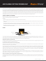
HOW A PLASMA CUTTER WORKS:
Basic plasma cutters use electricity to superheat air into plasma (the 4th state of matter), which is then blown through the metal to be cut. Plasma cutters
require a compressed air supply and AC power to operate.
Operation:
1. When the trigger is squeezed, DC current ows through the torch lead into the tip.
2. Next, compressed air ows through the torch head, through the air diffuser that spirals the air ow around the electrode and through the hole of the
cutting tip.
3. A xed gap is established between the electrode and the tip. (The power supply increases voltage in order to maintain a constant current through the
joint.) Electrons arc across the gap, ionizing and super heating the air creating a plasma stream.
4. Finally, the regulated DC current is switched so that it no longer ows to the tip but instead ows from the electrode to the work piece. Current and
airow continue until cutting is stopped.
NOTES:
The nozzle and electrode require periodic replacement. The electrode has an insert of tough high conductive material such as hafnium and cerium. This
insert erodes with use, also the tip orice will erode with use. Quality of the air used is paramount to longer life of electrodes and tips, in short clean dry
air gives longer parts life, the cleaner and dryer the better. We recommend use of a Plasma Air Filter.
What kinds of materials can the plasma cut?
Virtually any metal can be plasma cut including steel, stainless steel, aluminium, brass, copper, etc. Any thickness from 30 gauge through 30mm can be
cut, depending on the power of the plasma cutter used.
How Does Plasma Cutting Compare to Oxy-fuel (gas) cutting?
Plasma cutting can be performed on any type of conductive metal - mild steel, aluminium and stainless are some examples. With mild steel, operators
will experience faster, thicker cuts than with alloys.
Oxy-fuel cuts by burning, or oxidizing the metal it is severanceing. It is therefore limited to steel and other ferrous metals which support the oxidizing
process. Metals like aluminium and stainless steel form an oxide that inhibits further oxidization, making conventional oxy-fuel cutting impossible.
Plasma cutting however does not rely on oxidation to work and thus it can cut aluminium, stainless and any other conductive material. While different
gasses can be used for plasma cutting, most people today use compressed air for the plasma gas. In most shops, compressed air is readily available,
and thus plasma does not require fuel gas and compressed oxygen for operation.
Plasma cutting is typically easier for the novice to master, and on thinner materials, plasma cutting is much faster than oxy-fuel cutting. However, for
heavy sections of steel (25mm and greater), oxy-fuel is still preferred since oxy-fuel is typically faster and, for heavier plate applications high powered
plasma machines are required for plasma cutting applications.
What are the limitations to Plasma Cutting? Where is Oxyfuel preferred?
The plasma cutting machines are typically more expensive than oxy/acetylene. Also, oxy/acetylene does not require access to electrical power or
compressed air which may make it a more convenient method for some users. Oxyfuel can generally cut thicker sections (>25mm) of steel more quickly
than plasma.
AIR PLASMA CUTTING TECHNOLOGY

12 | RAZOR CUT 45 Manual
12
● Amperage
Standard rule of thumb is the thicker the material the more amperage required.
On thick material, set the machine to full output and vary your travel speed. On thinner material, you need to turn down the amper-
age and change to a lower-amperage tip to maintain a narrow kerf. The kerf is the width of the cut material that is removed during
cutting.
● Speed
Amperage and speed are critical to producing a good quality cut. The faster you move (especially on aluminium), the cleaner your
cut will be. To determine if you're going too fast or too slow, visually follow the arc that is coming from the bottom of the cut. The
arc should exit the material at a slight angle away from the direction of travel. If it's going straight down, that means you're going
too slow, and you'll have an unnecessary buildup of dross or slag. If you go too fast, it will start spraying back onto the surface of
the material without cutting all the way through. Because the arc trails at an angle, at the end of a cut, slow your cutting speed and
angle the torch in to cut through the last bit of metal.
● Direction
It is easier to pull the torch towards you than push it. The plasma stream swirls as it exits the tip, biting one side and nishing off
on the other leaving a bevelled edge and a straight edge. The bevel cut effect is more noticeable on thicker material and needs to
taken into consideration before starting your cut as you want the straight side of the cut to be on the nished piece you keep.
● Torch tip height & position
The distance and postion of the plasma torch cutting tip has an affect on the quality of the cut and the extent of the bevel of the cut.
The easiest way to reduce bevel is by cutting at the proper speed and height for the material and amperage that is being cut.
Correct torch height and
square to the material.
Minimum bevel & equal bevel
Longest consumable life
Torch angled to the material.
Unequal bevel, one side may
be excessively beveled.
Torch height too high.
Excessive bevel, plasma
stream may not cut all the
way through the material
Torch height too low.
Reverse bevel. Tip may
contact the work and short
out or damage the tip.
● Tip size and condition
The tip ori ces focus the plasma stream to the work piece. It is important to use the correct size tip for the amperage being used,
for example a tip with a 1.0mm ori ce is good for 0-40 amps whereas a 1.3mm ori ce is better for 40-80 amps. The low-amp tip has
a smaller ori ce which maintains a narrow plasma stream at lower settings for use on thin-gauge material. Using a 25 amp tip at an
60 amp setting will blow out and distort the tip ori ce and require replacement. Conversely, using an 80-amp tip on the lower set-
tings will not allow you to focus the plasma stream as well and creates a wide kerf. The condition of the tip ori ce is critical to the
quality of the cut result, a worn or damaged tip ori ce will produce a distorted plasma stream resulting in a poor cut quality.
● Electrode condition
Afi xed gap is established between the electrode and the inside of the cutting tip. Electrons arc across the gap, ionizing and super
heating the air creating the plasma stream. The electrode contains an insert in the end made of a highly conductive material called
hafnium. This insert erodes with use and develops a pit in the end of the electrode, when the pit becomes too much poor quality
cuts will result and necessitate replacement of the electrode.
New Tip Worn Tip
New Electrode Worn electrode
Operating Procedure & Techniques for PLASMA Cutting
AMPERAGE
Standard rule of thumb is the thicker the material the more amperage required.
On thick material, set the machine to full output and vary your travel speed. On thinner material, you need to turn down the amperage and change to a
lower-amperage tip to maintain a narrow kerf. The kerf is the width of the cut material that is removed during cutting.
SPEED
Amperage and speed are critical to producing a good quality cut. The faster you move (especially on aluminium), the cleaner your cut will be. To
determine if you’re going too fast or too slow, visually follow the arc that is coming from the bottom of the cut. The arc should exit the material at a slight
angle away from the direction of travel. If it’s going straight down, that means you’re going too slow, and you’ll have an unnecessary build-up of dross or
slag. If you go too fast, it will start spraying back onto the surface of the material without cutting all the way through. Because the arc trails at an angle,
at the end of a cut, slow your cutting speed and angle the torch in to cut through the last bit of metal.
DIRECTION
It is easier to pull the torch towards you than push it. The plasma stream swirls as it exits the tip, biting one side and nishing off on the other leaving a
bevelled edge and a straight edge. The bevel cut effect is more noticeable on thicker material and needs to taken into consideration before starting your
cut as you want the straight side of the cut to be on the nished piece you keep.
TORCH TIP HEIGHT & POSITION
The distance and position of the plasma torch cutting tip has an affect on the quality of the cut and the extent of the bevel of the cut. The easiest way to
reduce bevel is by cutting at the proper speed and height for the material and amperage that is being cut.
TIP SIZE AND CONDITION
The tip orices focus the plasma stream to the work piece. It is important to use the
correct size tip for the amperage being used, for example a tip with a 1.0mm orice is
good for 0-40 amps whereas a 1.3mm orice is better for 40-80 amps. The low-amp
tip has a smaller orice which maintains a narrow plasma stream at lower settings
for use on thin-gauge material. Using a 25 amp tip at an 60 amp setting will blow out
and distort the tip orice and require replacement. Conversely, using an 80-amp tip on
the lower settings will not allow you to focus the plasma stream as well and creates
a wide kerf. The condition of the tip orice is critical to the quality of the cut result, a
worn or damaged tip orice will produce a distorted plasma stream resulting in a poor
cut quality.
ELECTRODE CONDITION
A xed gap is established between the electrode and the inside of the cutting tip.
Electrons arc across the gap, ionizing and super heating the air creating the plasma
stream. The electrode contains an insert in the end made of a highly conductive
material called hafnium. This insert erodes with use and develops a pit in the end of the
electrode, when the pit becomes too much poor quality cuts will result and necessitate
replacement of the electrode.
Correct torch height and square to
the material. Minimum bevel & equal
bevel Longest consumable life.
Torch angled to the material.
Unequal bevel, one side may be
excessively bevelled.
Torch height too high. Excessive
bevel, plasma stream may not cut
all the way through the material
Torch height too low. Reverse bevel.
Tip may contact the work and short
out or damage the tip.
OPERATING PROCEDURE FOR
PLASMA CUTTING

RAZOR CUT 45 Manual | 13
13
Operating Procedure & Techniques for PLASMA Cutting
● Air pressure and volume
Air pressure, ow rate and air quality are critical to quality plasma cutting and consumable life span.
The required air pressure and volume can vary from model to model and the manufacturer will provide the specs.
The volume capacity of your compressor is important, if you have a small compressor with exactly the same l/min rating as the
plasma, then the compressor will run continuously when you are plasma cutting, a compressor with a l/min rating slightly higher
than the plasma would be more adequate. If you are doing a lot of cutting, cutting thick plate (same air consumption but slower
slower cut speeds = longer cut time) then choose a compressor at 1.5 to 2 times the plasma system requirement.
● Air quality
Good air quality is essential to quality plasma cutting and consumable life span.
Compressors take in air at atmospheric pressure and increase the pressure and store it in a tank. Humidity in the air is condensed
in the tank and in the airlines producing water, more so in humid environments. Moisture that forms in air lines has a tendency
to condense into larger drops when the air pressure decreases as it is entering the plasma torch. When these droplets enter into
the high temperatures (as much as 11,000°C) in the plenum of the torch, they immediately break down into oxygen and hydrogen,
which alters the normal chemical content of air in the torch. These elements will then dramatically change the plasma arc which
causes the torch consumable parts to wear very quickly, alters the shape of the nozzle ori ce, dramatically affecting cut quality in
terms of edge squareness, dross formation, and edge smoothness. Minimising the moisture in the air supply is absolutely critical to
quality plasma cuts and longevity of consumable parts. As a minimum be sure to drain the receiver (tank) on the air compressor at
least daily.
Most air plasma systems from reputable manufacturers have an on board particulate lter and or a coalescing lter with an auto
drain that will remove some moisture from the air supply. For home workshop and light industrial users the on board air lter is
adequate. Most situations however will require additional ltration to prevent moisture from affecting the quality of the plasma cutter
and in most cases it is recommended to install a sub micronic particulate lter that is designed to trap water through absorption.
This style of lter has a replaceable lter cartridge that absorbs water and must be changed after it is near saturation, it should be
installed close as possible to the air intake of the plasma cutter.
● Technique Tips
• It is easier to pull the torch through the cut than to push it.
• To cut thin material reduce the amperage until you get the best quality cut.
• Use the correct size tip ori ce for the amperage being used.
• For Straight cuts use a straight edge or cutting buggy as a guide. For circles, use a template or circle cutting attachment.
• Check that the front end consumable parts of the plasma cutting torch are in good condition.
Sub Micronic Filter Filter Element
● Starting a cut
Hold the torch vertical at the edge of the
work piece
Pull the trigger to start the pilot arc.
The cutting arc will initiate when the torch
tip is close enough to the work piece. Start
cutting on the edge until the arc has cut
completely through.
Then, proceed with the cut.
● Hand torch cutting technique
When cutting make sure that sparks are
exiting from the bottom of the work piece.
If sparks are spraying up from the work
piece, you are moving the torch too fast, or
you don't have enough amps set.
Hold the torch vertical and watch the arc as
it cuts along the line.
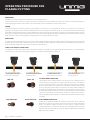
AIR PRESSURE AND VOLUME
Air pressure, ow rate and air quality are critical to quality plasma cutting and consumable life span. The required air pressure and volume can vary from
model to model and the manufacturer will provide the specs. The RAZOR CUT 45 air pressure must be adjusted and set to 0.5MPA (75psi) and requires
a ow rate of 190 l/min. The volume capacity of your compressor is important, if you have a small compressor with exactly the same l/min rating as the
plasma, then the compressor will run continuously when you are plasma cutting, a compressor with a l/min rating slightly higher than the plasma would
be more adequate. If you are doing a lot of cutting, cutting thick plate (same air consumption but slower cut speeds = longer cut time) then choose a
compressor at 1.5 to 2 times the plasma system requirement.
AIR QUALITY
Good air quality is essential to quality plasma cutting and consumable life span.
Compressors take in air at atmospheric pressure and increase the pressure and store it in a tank. Humidity in the air is condensed in the tank and in
the airlines producing water, more so in humid environments. Moisture that forms in air lines has a tendency to condense into larger drops when the air
pressure decreases as it is entering the plasma torch. When these droplets enter into the high temperatures (as much as 11,000°C) in the plenum of the
torch, they immediately break down into oxygen and hydrogen, which alters the normal chemical content of air in the torch. These elements will then
dramatically change the plasma arc which causes the torch consumable parts to wear very quickly, alters the shape of the nozzle orice, dramatically
affecting cut quality in terms of edge squareness, dross formation, and edge smoothness. Minimising the moisture in the air supply is absolutely critical
to quality plasma cuts and longevity of consumable parts. As a minimum be sure to drain the receiver (tank) on the air compressor at least daily.
Most air plasma systems from reputable manufacturers have an on board particulate lter and or a coalescing lter with an auto drain that will remove
some moisture from the air supply. For home workshop and light industrial users the on board air lter is adequate. Most situations however will require
additional ltration to prevent moisture from affecting the quality of the plasma cutter and in most cases it is recommended to install a sub micronic
particulate lter that is designed to trap water through absorption. This style of lter has a replaceable lter cartridge that absorbs water and must be
changed after it is near saturation, it should be installed close as possible to the air intake of the plasma cutter.
TECHNIQUE TIPS
• It is easier to pull the torch through the cut than to push it.
• To cut thin material reduce the amperage until you get the best quality cut.
• Use the correct size tip orice for the amperage being used.
• For Straight cuts use a straight edge or cutting buggy as a guide. For circles, use a template
or circle cutting attachment.
• Check that the front end consumable parts of the plasma cutting torch are in good condition.
OPERATING PROCEDURE FOR
PLASMA CUTTING

14 | RAZOR CUT 45 Manual
13
Operating Procedure & Techniques for PLASMA Cutting
● Air pressure and volume
Air pressure, ow rate and air quality are critical to quality plasma cutting and consumable life span.
The required air pressure and volume can vary from model to model and the manufacturer will provide the specs.
The volume capacity of your compressor is important, if you have a small compressor with exactly the same l/min rating as the
plasma, then the compressor will run continuously when you are plasma cutting, a compressor with a l/min rating slightly higher
than the plasma would be more adequate. If you are doing a lot of cutting, cutting thick plate (same air consumption but slower
slower cut speeds = longer cut time) then choose a compressor at 1.5 to 2 times the plasma system requirement.
● Air quality
Good air quality is essential to quality plasma cutting and consumable life span.
Compressors take in air at atmospheric pressure and increase the pressure and store it in a tank. Humidity in the air is condensed
in the tank and in the airlines producing water, more so in humid environments. Moisture that forms in air lines has a tendency
to condense into larger drops when the air pressure decreases as it is entering the plasma torch. When these droplets enter into
the high temperatures (as much as 11,000°C) in the plenum of the torch, they immediately break down into oxygen and hydrogen,
which alters the normal chemical content of air in the torch. These elements will then dramatically change the plasma arc which
causes the torch consumable parts to wear very quickly, alters the shape of the nozzle ori ce, dramatically affecting cut quality in
terms of edge squareness, dross formation, and edge smoothness. Minimising the moisture in the air supply is absolutely critical to
quality plasma cuts and longevity of consumable parts. As a minimum be sure to drain the receiver (tank) on the air compressor at
least daily.
Most air plasma systems from reputable manufacturers have an on board particulate lter and or a coalescing lter with an auto
drain that will remove some moisture from the air supply. For home workshop and light industrial users the on board air lter is
adequate. Most situations however will require additional ltration to prevent moisture from affecting the quality of the plasma cutter
and in most cases it is recommended to install a sub micronic particulate lter that is designed to trap water through absorption.
This style of lter has a replaceable lter cartridge that absorbs water and must be changed after it is near saturation, it should be
installed close as possible to the air intake of the plasma cutter.
● Technique Tips
• It is easier to pull the torch through the cut than to push it.
• To cut thin material reduce the amperage until you get the best quality cut.
• Use the correct size tip ori ce for the amperage being used.
• For Straight cuts use a straight edge or cutting buggy as a guide. For circles, use a template or circle cutting attachment.
• Check that the front end consumable parts of the plasma cutting torch are in good condition.
Sub Micronic Filter Filter Element
● Starting a cut
Hold the torch vertical at the edge of the
work piece
Pull the trigger to start the pilot arc.
The cutting arc will initiate when the torch
tip is close enough to the work piece. Start
cutting on the edge until the arc has cut
completely through.
Then, proceed with the cut.
● Hand torch cutting technique
When cutting make sure that sparks are
exiting from the bottom of the work piece.
If sparks are spraying up from the work
piece, you are moving the torch too fast, or
you don't have enough amps set.
Hold the torch vertical and watch the arc as
it cuts along the line.
14
● Piercing
Hold the torch at an angle to the work piece,
pull the trigger to start the arc and slowly
rotate it to an upright position.
When sparks are exiting from the bottom of
the work piece, the arc has pierced through
the material.
When the pierce is complete, proceed with
cutting.
● Safety Trigger Operation
The Suregrip SC80 torch supplied with the RazorCut 40 machine has a new design of safety trigger.
Just pull back on the trigger whilst increasing your grip and you will feel the trigger move to the on position.
When you release the pressure it will return to the off position.
off on off
Operating Procedure & Techniques for PLASMA Cutting
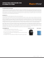
STARTING A CUT
HAND TORCH CUTTING TECHNIQUE
HAND TORCH CUTTING TECHNIQUE
SAFETY TRIGGER OPERATION
The Suregrip SC80 torch supplied with the RAZOR CUT 80 machine has a new design of safety trigger.
Just pull back on the trigger whilst increasing your grip and you will feel the trigger move to the on position.
When you release the pressure it will return to the off position.
Hold the torch vertical at the edge of the work
piece
Pull the trigger to start the pilot arc. The cutting
arc will initiate when the torch tip is close
enough to the work piece. Start cutting on the
edge until the arc has cut completely through.
Then, proceed with the cut.
When cutting make sure that sparks are exiting
from the bottom of the work piece.
If sparks are spraying up from the work piece,
you are moving the torch too fast, or you don’t
have enough amps set.
Hold the torch vertical and watch the arc as it
cuts along the line.
Hold the torch at an angle to the work piece,
pull the trigger to start the arc and slowly rotate
it to an upright position.
When sparks are exiting from the bottom of
the work piece, the arc has pierced through the
material.
When the pierce is complete, proceed with
cutting.
OPERATING PROCEDURE FOR
PLASMA CUTTING

RAZOR CUT 45 Manual | 15
1
8
9
4
5
2
3
7
6
Stand off cuttingContact cuttingGouging
10
12
13
14 15
11
17
1820
1619
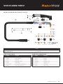
Part No.
Length 6m
SC80 PLASMA TORCH 6m WG-SC80-60-CC1
TORCH SPARE PARTS
Part-No Description
1SC8001 SC80 70 Torch Head Kit
2SC8014 Plasma Handle Kit
3SCSP1 Screw Pack
4SC2516 Plasma Safety Trigger
5SC8015 Location Block
6SC8019-60-CF4 Cable Assembly Complete X 6mt
7SC8050 Circle Cutting Attachment Kit
FRONT END CONSUMABLES
Part-No Description
8SC8002 Cooling Tube
9SC8004 Electrode
10 SC8006 Swirl Ring
11 SC8020-09 Cutting Tip 0.9mm
12 SC8020-10 Cutting Tip 1.0mm
13 SC8030 Retaining Cup
14 SC8040 Stand Off Guide
RATING: 80A AIR/N2 GAS, @ 60% DUTY CYCLE.
SC80 PLASMA TORCH

16 | RAZOR CUT 45 Manual
WARNING
There are extremely dangerous voltage and power levels present inside this unit.
Do not attempt to diagnose or repair unit by removing external cover unless you are an authorised repair agent for UNIMIG.
A. The cutting torch fails to ignite the arc, when torch trigger is pressed.
1. Gas pressure too high or too low, check and adjust gas pressure to 0.5MPA (75psi).
2. The shield cup is not installed correctly, turn off the power source, install and screw it down properly, then turn on the power source.
3. The electrode, swirl ring or cutting tip is not installed correctly, turn off the power source, install the electrode, swirl ring or cutting tip correctly,
and screw shield cup down properly, then turn on the power source.
B. The cutting torch fails to ignite the arc, when torch trigger is pressed the temperature lamp is on.
1. Power Supply is overheated (OC/OT lamp on), let unit cool down for at least 5 minutes. Make sure the unit has not been operated beyond Duty
Cycle limit. Refer to page 8 for duty cycle specications.
2. Faulty components in unit return for repair.
C. No cutting output; Torch activated, power source on; Gas ows; Fan operates
1. Torch not properly connected to power supply, check that torch leads are properly connected to power supply.
2. Work cable not connected to work piece, or connection is poor, make sure that work cable has a proper
3. Connection to a clean, dry area of the work piece.
4. Faulty components in unit return for repair
5. Faulty Torch, return for repair
D. Low cutting output
1. Incorrect setting of CURRENT (A) control, check and adjust to proper setting.
2. Faulty components in unit, return for repair.
E. Dicult Starting
1. Worn torch parts (consumables), shut off input power. Remove and inspect torch shield cup, cutting tip, swirl ring and electrode. Replace
electrode, cutting tip or swirl ring if worn; replace shield cup if excessive spatter has adhered to it.
F. Arc shuts off during operation; arc will not restart when torch switch is activated.
1. Power Supply is overheated (OC/OT lamp on), let unit cool down for at least 5 minutes. Make sure the unit has not been operated beyond Duty
Cycle limit. Refer to Section 2 for duty cycle specications.
2. 2 Torch consumables worn, check torch shield cup, swirl ring, cutting tip and electrode; replace as needed.
3. Faulty components in unit return for repair.
G. No gas ow; the power is lamp on; Fan operates
1. Gas not connected or pressure is too low, check gas connections. Adjust gas pressure to proper setting.
2. Faulty components in unit return for repair.
H. Torch cuts but low quality
1. Current (A) control set too low, increase current setting.
2. Torch is being moved too fast across work piece, reduce cutting speed.
3. Excessive oil or moisture in torch, hold torch 1/8 inch (3 mm) from clean surface while purging and
4. Observe oil or moisture build-up (do not activate torch). If there are contaminants in the air, additional ltering may be needed. Refer to sub-
micronic air lter page 8.
TROUBLE SHOOTING

RAZOR CUT 45 Manual | 17
Welding Guns Of Australia Pty Ltd (‘Us’, ‘We’) warrants that the following products under UNI-MIG, UNI-TIG, UNI-PLAS, UNI-FLAME, TECNA, T&R, HIT-
8SS & ROTA, supplied by Us and purchased by you from an Authorised UNI-MIG, UNI-TIG, UNI-PLAS, UNI-FLAME, TECNA, T&R, HIT-8SS & ROTA Dealer
throughout Australia are free of Material and Faulty Workmanship defects except for those products listed under ‘Warranty Exclusions’.
These terms and conditions supersede and exclude all former and other representations and arrangements relating to any warranties on these products.
WARRANTY PERIOD
We offer the following ‘Warranty Periods’ from ‘date of purchase’:
An Extended Warranty Period of 6 months total shall apply only to Machinery where offered and warranty is registered online.
UNI-MIG WELDING MACHINES
UNI-MIG DIY Series (Power Source Only) 2 Years (Clause 3)
UNI-MIG Procraft Series (Power Source Only) 3 Years (Clause 1&3)
UNI-MIG Trade Series (Power Source Only) 3 Years (Clause 1&3)
UNI-MIG Trade Series SWF (Power Source / Separate Wire Feeder Only) 3 Years (Clause 1&3))
UNI-MIG Workshop Series (Power Source Only) 3 Years (Clause 1&3)
UNI-MIG Workshop Series SWF (Power Source / Separate Wire Feeder Only) 3 Years (Clause 1&3)
UNI-MIG Jasic Inverter MIG (Power Source Only) 3 Years (Clause 3)
UNI-MIG Jasic Inverter MIG SWF (Power Source / Separate Wire Feeder Only) 3 Years (Clause 3)
UNI-TIG Jasic Inverter TIG (Power Source Only) 3 Years (Clause 3)
UNI-MIG Water Cooler 1 Year (Clause 3)
T&R Pulse MIG (Power Source Only) 2 Year (Clause 3)
T&R Pulse MIG SWF (Power Source / Separate Wire Feeder Only) 2 Year (Clause 3)
UNI-PLAS (Power Source Only) 3 Years (Clause 3)
UNI-PLAS Jasic Series (Power Source Only) 2 Years (Clause 3)
UNI-PLAS Site Cut Series (Power Source Only) 1 Year (Clause 3)
UNI-FLAME Gas Cutting and Welding Kits 3 Months (Clause 2&3)
UNI-FLAME Straight Line & Gas Cutting Machines (Power Source Only) 1 Year (Clause 3)
UNI-FLAME Regulators Argon/ Acetylene / Oxygen / LPG / Bobbin Flowmeter 1 Year
UNI-FLAME Automatic Welding Helmet 2 Years
UNI-MIG Automatic Welding Helmets 2 Years
TECNA (Power Source Only) 1 Year (Clause 3)
HIT-8SS Automatic Carriage (Power Source Only) 1 Year (Clause 3)
ROTA 102 Rotating table 1 Year
HOTBOX ElectrodeOven 1 Year
SPOTCAR 3500 1 Year (Clause 3)
TORCHES -GMAW, GTAW, MMAW, PLASMA, EARTH LEADS,
INTERCONNECTING CABLES, GAS HOSE 3 Months (Clause 3)
UNIMIG VIPER RANGE 1 Year
(Clause 1) 3 year warranty on transformers, inductor and rectier. 1 year warranty on PCB, and all other
components, .
(Clause 2) Gas Hose, Flashbacks are subject to and covered by the Manufacturer’s Individual Warranty, Contact the manufacturer for details
(Clause 3) This only Covers Manufactures defaults on all accessories for the rst three months after date of purchase.
WARRANTY TERMS

18 | RAZOR CUT 45 Manual
WARRANTY / RETURNS / EXCHANGES
We understand that sometimes you may need to return a product you have purchased from Welding Guns Of Australia PTY LTD Authorised Dealer
Network, to assist you, we have set out below the Welding Guns Of Australia PTY LTD Returns Policy that you should know.
Our Returns Policy includes the rights you have under the Australian Consumer Law and other relevant laws.
Your Rights under the Australian Consumer Law - Our goods come with guarantees that cannot be excluded under the Australian Consumer Law. You are
entitled to a replacement or refund for a major failure and for compensation for any other reasonably foreseeable loss or damage. You are also entitled
to have the goods repaired or replaced if the goods fail to be of acceptable quality and the failure does not amount to a major failure.
• You shall inspect the Goods on delivery and shall within seven (7) days of delivery (time being of the essence) notify Welding Guns Of Australia PTY
LTD of any alleged defect, shortage in quantity, damage or failure to comply with the description or quote.
• You shall also afford Welding Guns Of Australia PTY LTD the opportunity to inspect the Goods within a reasonable time following delivery if you believe
the Goods are defective in any way.
• If you shall fail to comply with these provisions the Goods shall be presumed to be free from any defect or damage. For defective Goods, which
Welding Guns Of Australia PTY LTD has agreed in writing that you are entitled to reject, Welding Guns Of Australia PTY LTD liability is limited to either (at
the Welding Guns Of Australia PTY LTD discretion) replacing the Goods or repairing the Goods except where you have acquired Goods as a consumer
within the meaning of the Trade Practices Act 1974 or the Fair Trading Acts of the relevant state or territories of Australia, and is therefore also entitled
to, at the consumer’s discretion either a refund of the purchase price of the Goods, or repair of the Goods, or replacement of the Goods.
Returns will only be accepted provided that:
a. You have complied with the provisions outlined above, and
b. Where the Goods are unable to be repaired, the Goods are returned at your cost within thirty (30) days of the delivery date, and
c. Welding Guns Of Australia PTY LTD will not be liable for Goods which have not been stored or used in a proper manner, and
d. The Goods are returned in the condition in which they were delivered and with all packaging material, brochures and instruction material in as new
condition as is reasonably possible in the circumstances.
• Welding Guns Of Australia PTY LTD Accepts no responsibility for products lost, damaged or mislaid whilst in transit
• Welding Guns Of Australia PTY LTD may (at their sole discretion) accept the return of Goods for credit but this may incur a handling fee of up to fteen
percent (15%) of the value of the returned Goods plus any freight costs.
• Where a failure does not amount to a major failure, Welding Guns Of Australia PTY LTD is entitled to choose between providing you with a repair,
replacement or other suitable remedy.
• Your rights under the Australian Consumer Law are not limited by a dened time. However, the Australian Consumer Law does recognise that the
relevant time period can vary from product to product, depending on factors such as the nature of the product and the price. Welding Guns Of Australia
PTY LTD adopts the same approach. As you can appreciate, the type of remedy we can offer you may also vary depending on how long it takes you to return
the product to us.
MAKING A CLAIM
If you wish to make a claim under this Warranty, you should:
• Return the product to the point of purchase either in person or on a prepaid courier; or
• Contact Us by Telephone on 02 9870 4200 or Mail PO Box 3033 Lansvale NSW 2166.
When returned, the product must be accompanied with the original invoice including the purchase price and disclosing the purchase date
All costs of installation, cartage, freight, travelling expenses, hiring tools and insurance are paid by the Customer.
To the extent permitted by law, our total liability for loss or damage of every kind related to the product in any way whatsoever is limited to the amount
paid to the retailer by you for the product or the value of the product.
No responsibility will be taken for products lost, damaged or mislaid whilst in transit.
WARRANTY TERMS

RAZOR CUT 45 Manual | 19
WARRANTY EXCLUSIONS
This Warranty covers Material and Faulty Workmanship defects only.
This Warranty does not cover damage caused by:
• Normal wear and tear due to usage
• Misuse or abusive use of the UNI-MIG, UNI-TIG, UNI-PLAS, UNI-FLAME, TECNA, T&R, HIT-8SS & ROTA, instructions supplied with the product.
• Failure to clean or improper cleaning of the product
• Failure to maintain the equipment such as regular services etc
• Incorrect voltage or non-authorised electrical connections
• Improper installation
• Use of non-authorised/non-standard parts
• Abnormal product performance caused by any ancillary equipment interference or other external factors
• Failure or any breakage caused by overload, dropping or abusive treatment or use by the customer
• Repair, modications or other work carried out on the product other than by an Authorised UNI-MIG, UNI-TIG, UNI-PLAS, UNI-FLAME, TECNA, T&R, HIT-
8SS & ROTA Service Dealer
Unless it is a manufacturing fault, this Warranty does not cover the following parts:
MIG Welding Torches and Consumables to suit, such as:
Gas Nozzles, Gas Diffusers, Contact Tip holder, Contact tip, Swan Necks, Trigger, Handle, Liners,Wire Guide, Drive Roller, Gas Nozzle Spring. Neck Spring,
Connector Block, Insulator, Gas Nipple, Cap, Euro Block, Head Assembly, Gas Block, Trigger Spring, Spring Cable Support, Neck Insulator, Shroud Spring,Gun
Plug Cover, Lock Nut, Snap On Head, Spring Cap, Ball, Motor 42 Volt, Pot 10K standard, Knob, Drive Roll Seat, Washer, Bow, Ball Bearing, Wire Condue
Nipple, Central Plug, Printed Circuit Board, Gun Plug House, Cable Support, Gas Connector, Handle To Suit PP36 with Knobs, All Xcel-Arc/ Magmaweld MIG
Welding Wires & Electrodes, Arc Leads, Welding Cable, Electrode Holder, Earth Clamps
TIG Welding Torches and Consumables to suit, such as:
Tungsten Electrodes, Collet, Collet Body, Alumina Nozzle, Torch Head, Torch Head water Cooled, Torch Head Flexible,Back Caps, Gas Lens, Torch Handle,
Cup Gasket, Torch Body Gas Valve, O-ring, All UNI-MIG TIG Welding Rods, All Xcel-Arc/ Magmaweld Electrodes, Arc Leads, Welding Cable, Electrode Holder,
Earth Clamps.
PLASMA Cutting Torches and Consumables to suit, such as:
All Cutting Tips, All Diffuser/Swirl Ring, All Electrode, Retaining Caps, Nozzle Springs, All Spacers, All Shield Caps, All Air and Power Cables, All Switches, All
O-rings, All Springs, All Circle Guides and Cutting Kits, Torch Bodies, Air Filter Regulator, Arc Leads, Welding Cable, Electrode Holder, Earth Clamps
STRAIGHT LINE CUTTING MACHINES and Consumables to suit, such as:
Hoses, Fittings, Track, Cutting Nozzles.
HIT-8SS Welding Carriage Consumables to suit, such as:
Input Cord, Inter-connecting Cord, Triggering Cable.
This Warranty does not cover products purchased:
• From a non-authorised UNI-MIG, UNI-TIG, UNI-PLAS, UNI-FLAME, TECNA,T&R, HIT-8SS & ROTA Dealer (such as purchases from unauthorised retailers
and purchases over the Internet from unauthorised local/international sellers or sites such as EBay)
• At an auction;
• From a private seller
Unless it is a manufacturing fault, this Warranty does not apply to any products sold to Hire Companies.
These conditions may only be varied with the written approval of the Directors of Welding Guns Of Australia PTY LTD
REMEMBER TO RETAIN YOUR ORIGINAL INVOICE FOR PROOF OF PURCHASE.
WARRANTY TERMS

Welding Guns Of Australia Pty Ltd
ABN: 14 001 804 422
PO Box 3033, Lansvale NSW 2166, AUSTRALIA
112 Christina Rd, Villawood, NSW 2163
Phone: 1300 864 644
Fax: (02) 9780 4244
Email: [email protected]
www.unimig.com.au
© Welding Guns Of Australia PTY LTD 2018
-
 1
1
-
 2
2
-
 3
3
-
 4
4
-
 5
5
-
 6
6
-
 7
7
-
 8
8
-
 9
9
-
 10
10
-
 11
11
-
 12
12
-
 13
13
-
 14
14
-
 15
15
-
 16
16
-
 17
17
-
 18
18
-
 19
19
-
 20
20


Ask a question and I''ll find the answer in the document
Finding information in a document is now easier with AI
Related papers
Other documents
-
 Jasic Plasma Cut Series User manual
-
Strata AdvanceCut45 User manual
-
ESAB SL60 SL100 1Torch Plasma Cutting Torch User manual
-
-
-
PROPOINT 9081357 Owner's manual
-
 Thermal Dynamics 1Torch SL100 Hand Torch User manual
-
 Top Gun PLASMA CUT 42 PFC Manual Manual
-
Everlast PowerPlasma 60S User manual
-
Lincoln Electric MASTERPIPE Mini Profiler Operating instructions


