Page is loading ...

User Manual
V1.0 2019 Copyright Safewaze
42” Beam Stanchion For
Horizontal Lifelines
Meets OSHA 1926.502 and 1910.140 Requirements
This manual is intended to meet the Manufacturer’s Instructions as
required by the American National Standards Institute (ANSI) Z359
and should be used as part of an employee training program as
required by the Occupational Safety and Health Act (OSHA).
220-00017

User Manual
V1.0 2019 Copyright Safewaze
1 GENERAL WARNINGS............... ..................... 3
2 INTRODUCTION AND SCOPE OF USE .......... 4
3 APPLICABLE SAFETY STANDARDS .............. 4
4 WORKER CLASSIFICATIONS ......................... 4
5 PRODUCT SPECIFIC APPLICATIONS ............ 5
6 LIMITATIONS .................................................... 5
7 CONNECTIONS ..............................................6-7
8 SPECIFICATIONS ...........................................7-8
9 INSTALLATION AND USE ..............................9-14
10 STANCHION COMPONENTS .......................13-14
11 BEAM CLAMP SIZING CHART & SPECS ...... 15
12 BEAM LOAD REQUIREMENTS TABLE .......... 16
13 INSPECTION AND MAINTENANCE ............... 17
14 INSPECTION LOG .......................................... 18
15 LABELS ........................................................... 19
Page 2
Table of Contents

User Manual
V1.0 2019 Copyright Safewaze
This product is part of a complete fall protection system. This Stanchion product can be used in
conjuction with any Safewaze HLL’s oered, or other HLL systems so long as that system’s anchor
requirements are below 4,000 lbs in order to meet the 2 to 1 safety factor on this 8,000 lbs. anchor
point. User’s must utilize, and connect to a Safewaze HLL system with ANSI Z359 compliant
restraint or Personal Fall Arrest Systems (PFAS). This product is not designed, nor should be used
as a component for a Postioning, Suspension, or Rescue System. A PFAS is typically composed of a
Full Body Harness, Anchorage, and a Connecting Device. Connecting Devices used with Safewaze
HLL’s are Energy Absorbing Lanyards (EAL’s) or a Self Retracting Device (SRD). The connection
point to the FBH for use of a Safewaze HLL is the Dorsal D-ring.
Page 3
WARNING
These instructions must be provided to any person utilizing this equipment. The worker must read
and understand the manufacturer’s instructions for this, and all other components of the complete Fall
Protection System. These instructions must be followed for the proper use, maintenance, and
inspection of this equipment. These instructions must be kept and made available to worker’s at all
times. Any alteration, misuse, or use of this equipment outside the scope of the manufacturer’s
instructions, may result in serious injury or death.
A comprehensive Fall Protection Plan must be kept on le and available to all employees at all times.
The employer and user’s of this equipment must be properly trained in the installation, use,
inspection, and maintenance of this equipment.
The maximum weight capacity of this equipment is 310 lbs. (including tools and equipment) as
specied by ANSI. Certain Safewaze products mentioned in this manual may have maximum weight
capacities in excess of 310 lbs. Although certain components of the overall Personal Fall Arrest
System may have weight weight capacities in excess of 310 lbs., use of the Safewaze Stanchion in a
Horizontal Lifeline System limits the weight of each user to 310 lbs.
Consult your doctor if there is reason to doubt your tness to safely absorb the shock from a fall
arrest. Age and tness seriously aect a worker’s ability to withstand falls. Pregnant women or minors
must not use this equipment. Failure to heed this warning may result in serious injury or death.
User’s of this equipment must read and understand this manual in it’s entirety prior to use.
Contact Safewaze if you have questions, regarding compatibility of this equipment, that are not
covered in this manual. Do not alter or misuse this equipment. Some subsystem components could
aect the performance and the operation of this equipment. Do not anchor this product to moving
machinery, or hazards that have chemical, electrical or gaseous characteristics. Failure to comply
with this warning could result in serious injury or death.

User Manual
V1.0 2019 Copyright Safewaze Page 4
Applicable Safety Standards and Regulations
Worker Classifications
Understand the denitions of those who work in proximity of or may be
exposed to fall hazards.
Qualied Person: A person with an accredidated degree or certication, and with extensive
experience or sucient professional standing, who is considered procient in planning and reviewing
the conformity of fall protection and rescue systems.
Competent Person: A highly trained and experienced person who is assigned by the employer
to be responsible for all elements of a fall safety program, including, but not limited to, its regulation,
management, and application. A person who is procient in identifying existing and predictable
hazards, and who has the authority to stop work in order to eliminate hazards.
Authorized Person: A person who is assigned by their employer to work around or be subject to
potential or existing fall hazards.
It is the responsibility of a Qualied or Competent person to supervise the job site and ensure
safety regulations are complied with.
Introduction & Scope of Use
Thank you for purchasing a Safewaze Stanchion for Horizontal Lifelines (HLL). This manual must be
read and understood in its entirety, and used as part of an employee training program as required by
OSHA or any applicable state agency.
This manual and any other instructional material must be available to the user of the equipment.
The user must understand how to safely and eectively use the Safewaze Stanchion, and all fall
protection equipment used in conjunction with the stanchion.
The Safewaze Stanchion has been designed for your safety. These stanchions, when used in
conjuction with HLL lsystems are designed to oer users a exible and easily removable anchor point.
ANSI Z359.0 Denitions and Nomenclature Used for Fall Protection and Fall Arrest
ANSI Z359.1 Safety Requirements for Personal Fall Arrest Systems, Subsystems, and Components
ANSI Z359.2 Minimum Requirements for a Comprehensive Managed Fall Protection Program
ANSI A10-14 Safety Requirements for Safety Belts, Harnesses, Lanyards, and Lifelines for Construction and
Demolition Use
ANSI A10.32 Personal Fall Protection use in Construction and Demolition
ANSI STANDARDS
OSHA REGULATIONS
OSHA 1910.66 Personal Fall Arrest Systems
OSHA 1926.502 Fall Protection Systems Criteria and Practices

User Manual
V1.0 2019 Copyright Safewaze Page 5
Personal Fall Arrest: Safewaze Stanchions, when installed as part of a HLL System, can be used
as part of a complete Personal Fall Arrest System (PFAS). The maximum number of users is dictated
by the Safewaze HLL system being utilized with the stanchions. The structure utilized for attachment
must be capable of withstanding a load of 5,000 lbs in all directions permitted by the system. The
maximum allowable free fall is 6 ft, with the maximum combined length of the fall arrester, lanyard
extension, and D-ring being 36 inches.
Product Specific Applications
Lanyard Length
(6’ Total)
Deceleration
distance (4’ total)
Height of harness dorsal
D-ring from
worker’s feet
(6’ total)
Safety factor
(2’ total)
Required
distance
from
Anchorage
(18’ total)
Fall Clearance: There must be sucient clearance below the anchorage connector to arrest a fall
before the user strikes the ground or an obstruction. When calculating fall clearance, account for a
MINIMUM 2’ safety factor, deceleration distance, user height, length of lanyard/SRL, and all other
applicable factors (See Figure 1).
Limitations
Fall Clearance Diagram
***Diagram shown is an example
fall clearance calculation ONLY.
For all applications: worker weight capacity range
(including all clothing, tools, and equipment) is 130-310 lbs
Fig. 1
**USER SHOULD REFER TO HLL INSTRUCTIONS FOR PROPER CLEAR FALL SPECIFICS**

User Manual
V1.0 2019 Copyright Safewaze
Swing Falls: Prior to installation or use, make considerations for eliminating or minimizing all swing
fall hazards. Swing falls occur when the anchor is not directly above the location where a fall occurs.
Always work as close to in line with the anchor point as possible. Swing falls signicantly increase
the likelihood of serious injury or death in the even of a fall. (See Figure 2)
FALLSAFE USA
COMPATIBILITY OF CONNECTIONS
Connectors are compatible with connecting elements when they have been designed to work together
in such a way that their sizes and shapes do not cause their gate mechanisms to inadvertently
open regardless of how they become oriented. Connectors (hooks, carabiners, and D-rings) must
be capable of supporting at least 5,000 lbs. (22.2 kN). Connectors must be compatible with the
anchorage or other system components (see Figure 4). Do not use equipment that is not compatible.
Non- compatible connectors may unintentionally disengage (see Figure 3). Connectors must be
compatible in size, shape, and strength. Self-locking snap hooks and carabiners are required by
ANSI Z359 and OSHA guidelines. Contact Safewaze if you have any questions about compatibility.
Fig. 3 - UNINTENTIONAL DISENGAGEMENT
Non-compliant part
3 - gate opens
2 - gate presses
against
non-complaint
part
4 - and parts disengage.
1 -
NOTE: SOME SPECIALITY CONNECTORS HAVE ADDITIONAL REQUIREMENTS.
CONTACT Safewaze WITH QUESTIONS.
Fig. 2
Page 6
Using a connector that is undersized or irregular in shape (1) to connect a snap hook or carabiner
could allow the connector to force open the gate of the snap hook or carabiner. When force is applied,
the gate of the hook or carabiner presses against the non-compliant part (2) and forces open the gate
(3). This allows the snap hook or carabiner to disengage (4) from the connection point.
Connections

User Manual
V1.0 2019 Copyright Safewaze Page 7
MAKING CONNECTIONS
Snap hooks and carabiners used with this equipment must be double locking and/or twist lock.
Ensure all connections are compatible in size, shape and strength. Do not use equipment that is not
compatible. Ensure all connectors are fully closed and locked.
Safewaze connectors (snap hooks and carabiners) are designed to be used only as specied in each
product’s user’s instructions. See Fig. 4 for examples of inappropriate connections. Do not connect
snap hooks and carabiners:
• To a D-ring to which another connector is attached.
• In a manner that would result in a load on the gate (with the exception of tie back hooks).
NOTE: Large throat snap hooks must not be connected to standard size D-rings or
similar objects which will result in a load on the gate if the hook or D-ring twists or
rotates, unless the snap hook complies with ANSI Z359.12 and is equipped with a 3,600
lb (16 kN) gate. Check the marking on your snap hook to verify that it is appropriate for
your application.
• In a false engagement, where features that protrude from the snap hook or carabiner catch on the
anchor, and without visual conrmation seems to be fully engaged to the anchor point.
• To each other.
• By wrapping the web lifeline around an anchor and securing to lifeline except as allowed for Tie
Back models.
• To any object which is shaped or sized in a way that the snap hook or carabiner will not close and
lock, or that roll-out could occur.
• In a manner that does not allow the connector to align properly while under load.
Fig. 4 - INAPPROPRIATE CONNECTIONS
Specifications

User Manual
V1.0 2019 Copyright Safewaze Page 8
The Safewaze Stanchion, Horizontal Lifeline system, and its subsystems, must be inspected prior to
each use for:
• Wear, damage, and other deterioration.
• All snaphooks and carabiners must be able to self-close and lock.
• Check the operation of self retracting lanyards by pulling smoothly on the lifeline, then pull sharply
on the lifeline to engage the locking mechanism.
• All rope / wire rope must be inspected for tears, cuts, fraying, abrasion, unsplicing, discoloration,
corrosion, heat damage, bird caging, burrs, kinks, or other signs of wear and damage.
• Sewn terminations should be secure, complete, and not visibly damaged.
• All rope splices / cable connections should be secure.
• Systems used with the Safewaze stanchion must be properly tensioned per system instructions.
• No load indicators shall be deployed.
• Damaged and other deteriorated and defective components must be immediately removed from
service, in accordance with the requirements of OSHA 29 CFR 1910.66 and 1926.502.
Care should be taken to avoid moving machinery, and chemical or electrical hazards during
installation of the stanchion. Contact with such hazards may cause serious injury or death.
Weight capacities dened in this manual for the stanchion and HLL systems must be adhered to in
order to avoid possible failure of the system.
The stanchion and any other associated PFAS subsystems must be removed from service if
exposed to Fall Arrest Forces.
Contact Safewaze if using this equipment in a manner, or in combination with other equipment,
not specically dened in this manual.
Avoid sharp or abrasive surfaces.
Eletrical hazards must be avoided. Potential Arc Flash from arc welding operations, as well as
accidental Arc Flash from electrical equipment, can damage equipment and cause serious injury or
death.
Never use combinations of components or subsystems that may aect, or interfere with the safe
function of each other.
WARNING: The Safewaze Stanchion is NOT designed for use as a single point
connection for an individual PFAS system. Never attach a PFAS system directly to the
stanchion for individual use as this may cause improper loading of the stanchion, resulting
in damage to, or failure of, the stanchion. The Safewaze Stanchion for Temporary
Lifelines is desgined for use with all Safewaze Horizontal Lifeline Systems unless an
Intermediate Stanchion is required. If an Intermediate Stanchion is utilized, a cable HLL
system must be installed.

User Manual
V1.0 2019 Copyright Safewaze Page 9
Installation and Use
Before Each Use
Users of personal fall arrest systems must have a rescue plan in place, if the user cannot rescue
themselves, as well as the means to carry out the rescue.
The user must read and understand these User Instructions, as well as the User Instructions for every
component/subsystem of the personal fall arrest system.
WARNING: If utilizing an intermediate post with a Rope HLL, the user should pay special
attention when inspecting the rope lifeline. Use of the intermediate stanchions with a
Rope HLL system could enhance wear of the lifeline component. Addtional inspection of
the rope lifeline is required at intermediate post attachments.
The Safewaze Stanchion is available with 2 dierent clamp sizes from 4” minimum to either 18” or 24”
maximum. The stanchion secures to the top ange of an I-Beam. The stanchion will t a maximum
ange thickness of 2-1/4”. Installation of two stanchions in line on an I-Beam provides an attacment /
anchorage point for Safewaze Horizontal Lieline Systems. Some Safewaze Horizontal Lifeline
systems allow for intermediate stanchions to be installed along the Horizontal Lifeline span to
provide stability and possible reduction of required fall clearances. In the event an intermediate post
is required, an intermediate post pass through assembly (Part # 019-8039) is available, which does
not require a user to disconnect from the system to pass by the intermediate stanchion.
All components of the stanchion must be inspected prior to installation and before each use. During
pre-use inspection, all mounting bolts, and the wing-nut should be re-tightened to ensure proper
installation of the stanchion. Additionally the stanchion must be inspected by a Competent Person on
an annual basis. Recording of inspections can be completed on the inspection grid of the stanchion’s
label. Inspections can also be recorded in the Inspection Log on Page 17 of this manual.
Safewaze horizontal lifeline stanchions are designed to be installed on horizontal steel beams that
are straight with no bends. When installaed, the stanchion provides a 42” connection height from the
top surface of the beam.
When installing the Safewaze stanchions with Safewaze Horizontal Lifelines, the user must pay close
attention to the instructions provided with each particular Horizontal Lifeline System. Each Safewaze
Horizontal Lifeline system has unique characteristics in regards to the maximum number of users,
required fall clearances, and dynamic sag. Each Safewaze HLL system must be installed per the
manufacturer’s instruction manual provided with the system.
If multiple user’s are connected to the HLL system simultaneously (See specifc HLL instructions for
maximum number of user’s allowed), the user’s must be aware that in the event of a fall by one
worker, the other individuals connected to the system could also be pulled o of the working surface
as the lifeline delects. It is recommended that each person has an independent HLL system, or that
shorter span lengths are used to minimize the potential for other worker’s falling.
Specic information such as fall clearances, maximum span length, maximum number of users, and
other technical data is included in the individual HLL system instruction manuals. The maximum
Horizontal Lifeline span length for use with the Safewaze Stanchions is 60 ft. The span length can be
increased with the use of intermediate stanchions to create multiple spans.

User Manual
V1.0 2019 Copyright Safewaze Page 10
Fig. 5 Fig. 6
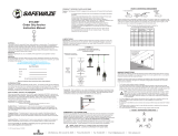
Unpackage the upright and base. Inspect both components to ensure no damage has occurred
during shipment (See Fig.5). Unpackage the provided bolts and lock nuts to be used for assembly.
Slide upright into base and align holes in each component. Insert stanchion bolts through the
assembly (See Fig. 6). Thread a lock nut onto the end of each stanchion bolt and tighten to ensure
secure t.
(2) Bolts
(2) Lock Nuts

User Manual
V1.0 2019 Copyright Safewaze Page 11
Fig. 7
Fig. 8
Insert threaded end of clamp assembly through the pre cut slot in base. Loosely thread the wing nut
onto the end of the clamp assembly (See Fig. 7).
Place entire assembly on top surface of I-Beam at desired installation location. Capture top of
I-Beam with the clamp assembly on one side, and the slotted portion of the base assembly on the
other side. Tighten the clamp assembly to the top of the I-Beam by rotating the wing nut in a
clockwise direction until secure (See Fig 8-A). When hand tight, strike the wing nut with a hammer or
further tighten with an adjustable wrench to ensure stanchion is secured to I-Beam. Tighten the
mounting bolts down onto top of I-Beam to secure the stanchion into place (See Fig 8-B). Install
Cotter Pin through end of Beam Clamp. Installed assembly should appear as indicated in
Fig. 9 (See Page 12).
A
B

User Manual
V1.0 2019 Copyright Safewaze Page 12
Fig. 9
Fig. 10
If stanchion is to be used as an intermediate post, the intermediate pass through bracket must be
installed. At the top of the upright, align the pre-drilled holes in the pass through bracket with the
pre-drilled holes in the stanchion (See Fig. 10). Insert the provied bolts through the holes and thread
the locking nuts onto the end of the bolts. Tighten until pass through bracket is secure to the top of
the upright.
Stanchion assembly
correctly installed on
top surface of I-Beam.

User Manual
V1.0 2019 Copyright Safewaze Page 13
Fig. 11
As the user reaches an intermediate stanchion, pass the snap hook under the rst side of the
intermediate bracket. When the snap hook is between both sides of the intermediate bracket, rotate
the snap hook to the other side of the Horizontal Lifeline, and pass the snap hook under the other
side of the intermediate bracket (See Fig 11). There is no need to disconnect the snap hook from the
Horizontal Lifeline.
Stanchion Components and Part Numbers
019-8038
Complete Assembly for
I-Beams 4” to 18”
020-8060
Complete Assembly for
I-Beams 4” to 12”
019-8046
Complete Assembly for
I-Beams 4” to 24”

User Manual
V1.0 2019 Copyright Safewaze Page 14
019-8040
I-Beam
Upright
019-8047
Base for I-Beams 4” to 18”
019-8041
Base for I-Beams 4” to 24”
019-8039
Upright Pass Through
Bracket
019-8045
I-Beam Clamp for I-Beams 4” to 18”
019-8042
I-Beam Clamp for I-Beams 4” to 24”
019-8043
I-Beam Clamp Wing Nut

User Manual
V1.0 2019 Copyright Safewaze Page 15
Beam Clamp Sizing Diagram
Specifications Table
XY
020-8060
X
Y≤ 2-1/4”
4” - 12”
019-8038
≤ 2-1/4”
4” - 18”
019-8046
≤ 2-1/4”
4” - 24”
Part #
Minimum
Tensile Strength
and Material
8,000 lbs.
Minimum Tensile
Strength
Refer to
SafeWaze HLL
Instruction Manuals
OSHA 1926.502
OSHA 1910.140
Stanchion Upright:
Steel
Stanchion Base:
Steel
Fasteners:
Grade 5
019-8038
I-Beams
4”-18” Width
020-8060
I-Beams
4”-12” Width
019-8046
I-Beams
4”-24” Width
Maximum User
Capacity
Standards and
Regulations I-Beam Stanchion

User Manual
V1.0 2019 Copyright Safewaze Page 16
Safewaze HLL
System Part Number Conguration A B
2 Person
Kernmantle HLL
019-8000
019-8001
019-8002
019-8003
1 Worker 2,800 lbs. 1,500 ft-lbs.
2 Workers 5,400 lbs. 3,000 ft-lbs.
4 Person
Double Braid Rope
HLL
019-8012
019-8013
019-8014
019-8015
1 Worker 3,400 lbs. 1,500 ft-lbs.
2 Workers 5,400 lbs. 3,000 ft-lbs.
2 Person
Cable HLL
019-8016
019-8017
019-8018
019-8019
1 Worker 5,400 lbs. 1,500 ft-lbs.
2 Workers 6,600 lbs. 3,000 ft-lbs.
4 Person
Cable HLL
FS-EX10000
FS-EX10500
1 Worker 2,000 lbs. 1,500 ft-lbs.
2 Workers 4,000 lbs. 3,000 ft-lbs.
A
B
Beam Load Requirments - End Anchor Stanchions

User Manual
V1.0 2019 Copyright Safewaze Page 17
Maintenance
Any Safewaze stanchion components requiring maintenance must be tagged
“unusable” and removed from service. Bolts and lock nuts can be replaced if
necessary by the user so long as equivalent to those provided during shipment.
Cleaning maintenance may be performed by the user.
Repairs to the product may only be made by the manufacturer or entities authorized in
writing by the manufacturer.
THIS SYSTEM MUST ONLY BE SERVICED BY A TRAINED AND COMPETENT INDIVIDUAL!
NEVER ATTEMPT TO SERVICE THIS UNIT OR TAMPER WITH ITS FUNCTION IN ANY WAY!
Storage
When not installed, the Safewaze stanchion should be stored in a cool, dry place out of
direct sunlight. Do not store in areas where damage from environmental factors such
as heat, light, excessive moisture, oil, chemicals and their vapors, or other degrading
elements may be present. Do not store damaged equipment or equipment in need of
maintenance in the same area as product approved for use. Equipment that has been
stored for an extended period must be inspected as described in these User
Instructions prior to use.
Inspection and Maintenance
Inspection
Inspect the stanchion for corrosion and/or damage.
Check the upright and base for signs of distortion or deformation.
Inspect stanchion assembly bolts and nuts prior to each use, and re-tighten as needed.
Inspect all components of HLL system per the manufacturer’s instrutions.
Frequency
All components of the Safewaze stanchion assembly must be inspected prior to each
use, and annually by a “competent person” (other than the user), as dened by OSHA.
Criteria
If inspection reveals any defect, inadequate maintenance, or unsafe condition, remove
from service until a “qualied person” as dened by OSHA 1926.32(m) can determine
the need for authorized repair or disposal.

User Manual
V1.0 2019 Copyright Safewaze
Inspection Log
DATE INSPECTED
BY:
CONDITION OF SYSTEM
Page 18

User Manual
V1.0 2019 Copyright Safewaze
Labels
Page 19
This product must be used in accordance with the manufacturers
instructions provided at shipment. For use only with approved SafeWaze
temporary Horizontal Lifeline (HLL) systems. Specifc information such as
fall clearances, number of users, span length, etc..., for approved HLL
systems are included in the individual HLL system instructions. User’s must
be trained in the use of this product and associated HLL systems. This
equipment must be installed and used under the supervision of a Qualified
Person. Failure to follow instructions, misuse, or alteration of this product
may result in serious injury or death. Use of this equipment near thermal,
electrical, chemical or other hazards should be avoided. Do not utiliize this
equipment if unsafe or hazardous conditions are present. Inspection results
should be recorded in the inspection log on this label, and the inspection
log located in the instruction manual.
DO NOT REMOVE THIS LABEL
Material: Steel
Meets OSHA 1926.502 and 1910.140 Requirements
www.safewaze.com
JAN FEB MAR APR MAY JUN JUL AUG SEP OCT NOV DEC
Model #:
019-8038 019-8040 019-8046
Date of Mfr.: XX/XXXX
Serial Number: XXXXXXX
Upright
Base
Mounting Bolt Clamp
019717
INSTALLATION
Tighten the clamp to the I-Beam using the supplied wing nut. After hand
tightening, strike the wing nut with a hammer, or continue tightening with an
adjustable wrench to ensure clamp is secure to I-Beam. Once complete,
tighten mounting bolts to top of I-Beam.
SafeLink 42" I-Beam Stanchion
WARNING
STANCHION
STANCHION

User Manual
V1.0 2019 Copyright Safewaze
WARRANTY
Safewaze
225 Wilshire Ave SW
Concord, NC 28025
PHONE: 1-800-230-0319
FAX: 1-704-262-9051
EMAIL: [email protected]
Web: safewaze.com
Page 20
/