Page is loading ...

Texmate, Inc. Tel. (760) 598-9899 • www.texmate.comRP-35A Autozeroing Panel Meter Manual (d0059) Page 1
General Features Specifications
Typical Application Connections
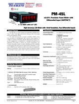
RP-35A
A Precision Autozeroing
High Input Impedance
Differential Panel Meter
with Switching AC/DC Power supply
3 1/2 Digit 0.56” LED
In a NEMA Style Case
The Texmate Model RP-35A is a precision, autozeroing when 0V
applied, 31⁄2 digit meter designed to fit most other manufacturers’
panel cutouts, in clud ing DIN/NEMA standard. It measures bipo-
lar differential and single-ended DC voltages over three user-pro-
grammable ranges from ±1.999 to ±199.9VDC full-scale. For
other 4-20 mA, ACV, ACA and DCA applications, the suggested
meter in the same case size is the UM-35-CL, UM-35-DCA,
UM-35-ACV and UM-35-ACA.
The UM-Series also has temperature and pressure meters that
are in the same case size as the RP-35A.
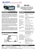
DC Volts Single-Ended measurement with
a resolution of 100 mV.
DC Volts Differential measurement with
a resolution of 100 mV.
On the back side of PCB,
cut track of pin 2 and pin 3
for differential function
Input Configuration: ......True differential and single-ended
Full Scale Ranges: ........±1.999VDC (standard)
±19.99VDC
±199.9VDC
Input Impedance: ...........Exceeds 1000MΩ on 2V range;
>1MΩ on all other ranges
Input Protection: ............Do not exceed ± 400VDC
Accuracy: .......................±(0.05% of reading = 1 digit)
Temperature Coefficient: ..5PPM/°C in ratiometric operation;
60PPM/°C Typ. using internal
reference on 2V range.
Warm Up Time: ..............10 minutes to specified accuracy
Conversion Rate: ...........3 readings per second nominal,
controllable from 1 to 20 readings
per second
Display:...........................0.56" LED
Decimal Selection: ........User programmable to 4 positions
Overrange Indication: ...When input exceeds full scale on
any range being used, most
significant “1” digit & “-” symbol (for
negative inputs) is displayed with all
other digits blanked
Power Requirements: ...85-305 VAC, 120-420VDC,50/60Hz
Approx. 1.5W
Operating Temperature: ....-10° to +50°C
Storage Temperature: ...-20° to +70°C
Relative Humidity ..........95% (non-condensing)
Case Dimensions: .........Bezel 3.78” Wx1.89” H (96mm x 48mm)
Depth behind bezel 3.36" (83.5mm)
Plus 0.66" (17 mm) connectors
Weight: .............................5.6 oz (0.16 kg)
8 oz (0.23 kg). when packed.
DC Volts
+
_
PIN 2 Internally
Connected
DC Volts
+
Ground
_2
Cut

RP-35A Autozeroing Panel Meter Manual (d0059)Texmate, Inc. Tel. (760) 598-9899 • www.texmate.comPage 2
Calibration Procedure Select Input Range
Connector Pinouts
!
This meter uses plug-in type screw terminal connectors for all
input and output connections. The power supply connections
(pins 14 and 15) have a unique plug and socket outline to
prevent cross connection. The main board uses standard right-
angled connectors.
Connectors
WARNING: AC and DC input signals and power
supply voltages can be hazardous. Do Not connect
live wires to screw terminal plugs, and do not insert,
remove or handle screw terminal plugs with live wires
connected.
Optional Face Plate Descriptors
Custom Face Plates
Texmate Produces Thousands of Custom OEM Face Plates.
Have Texmate Design and produce a Custom Face Plate for your next
project!
• Custom face plates have a non-recurring artwork charge. A serial
number is then assigned to each artwork to facilitate reordering.
Removable
Key-lock
Safety
Catch
Cover
Base
O-ring
Gasket
NEMA-4X, IP65 Lockable Cover
(Part Number OP-N4X/96X48)
Clear Lockable Water-proof Cover
The clear lockable cover is designed to be dust and waterproof
to NEMA-4X, IP65 standards. The assembly consists of a base
and a cover with a cam hinge and key-lock fastening mecha-
nism. An O-ring, or neoprene gasket forms a seal between the
base and the panel. The cam hinge prevents the cover from
closing when opened until pushed closed. The cover has a
tapered recess that, when closed, forms a seal with a tapered
spigot on the base. A key-lock employs a cam locking device to
force the spigot into the recess, ensuring seal integrity. A safety
catch keeps the cover closed even when the key is removed,
and the keyhole can be used to attach a safety seal clip,
preventing unauthorized
opening.
To open meter, insert a flat
head screwdriver or similar
instrument in both slots on the
side of the cover and pry open.
The RP-Series meters slide
out from the front of the case
as a complete assembly.
To customize the face plate,
clear adhesive label contain-
ing various popular descriptors
may be ordered. Choose the
descriptor desired, peel off the
adhesive backing and align the
descriptor in the center right of
the faceplate.
P.N.: DU-CASEDES
Signal Conditioning Components
SPAN Potentiometer (Pot)
The SPAN pot is on the right side of the signal
input. Typical adjustment is 20% of the input
signal range.
Apply power to the meter. Then with a pre ci sion DC reference
source apply +1.900 VDC be tween the Signal High Input Pin 1
and Signal Low Input Pin 3 . Adjust SPAN po ten ti om e ter until the
display reads +1.900 V. Note: The volt age applied in this case
is for a +2.000 V full-scale meter. For other ranges, the voltage
applied should be similarly proportional to the particular full-scale
voltage.
Decimal
Select
Header
1.XXX
1X.XX
1XX.X
1XXX.
Power
SPAN
Signal Input Pin
REAR VIEW
AC
Neutral
– DC
AC
Line
+ DC
1
+ +
2 3 4 5
HOLD
Input LO / GND
Input HI
Excitation +5V
Internally
Connected
Differential input only
Decimal selection is made by
moving the jumper to the indi-
cated position on the header
for the decimal required.
2V is factory
pre-installed

Texmate, Inc. Tel. (760) 598-9899 • www.texmate.comRP-35A Autozeroing Panel Meter Manual (d0059) Page 3
RP Case Dimensions and Panel Cutouts
Mounting Clip
Panel Cutout 1.64"
(41.6mm)
3.36"
(85.3 mm)
3.58"
(91mm)
3.78"
(96 mm)
3.58"
(90.8 mm)
1.89"
(48 mm)
1.55"
(39.3 mm)
2 PCS
FRONT VIEW
REAR VIEW
SIDE VIEW
SIDE VIEW
0.78"
(19.8 mm)
0.55"
(14 mm)
2.8"
(71.2 mm)
RP Series NEMA Case Dimensions and Panel Cutouts
Decimal
Select
Header
1.XXX
1X.XX
1XX.X
1XXX.
Power
SPAN
Signal Input Pin
Ordering Information
Warranty
WARRANTY
Texmate warrants that its products are free from defects in material
and workmanship under normal use and service for a period of one
year from date of shipment. Texmate’s obligations under this warranty
are limited to replacement or repair, at its option, at its factory, of any
of the products which shall, within the applicable period after shipment,
be returned to Texmate’s facility, transportation charges pre-paid, and
which are, after examination, disclosed to the satisfaction of Texmate
to be thus defective. The warranty shall not apply to any equipment
which shall have been repaired or altered, except by Texmate, or which
shall have been subjected to misuse, negligence, or accident. In no
case shall Texmate’s liability exceed the original purchase price. The
aforementioned provisions do not extend the original warranty period
of any product which has been either repaired or replaced by Texmate.
1934 Kellogg Ave., Carlsbad, CA 92008
Tel: 1-760-598-9899 • 1-800-TEXMATE • Email: orders@texmate.com
RP Series Technical Manual Copyright © 2022 Texmate Inc. All rights re-
served. Published by: Texmate Inc. USA. Information in this Technical Manu-
al is subject to change without notice due to correction or enhancement. The
information described in this manual is proprietary to Texmate, Inc. and may
not be copied, reproduced or transmitted, in whole or in part, in connection
with the design, manufacture, or sale of apparatus, device or private label
product without the express written consent of Texmate, Inc.
User's Responsibility
USER’S RESPONSIBILITY
We are pleased to offer suggestions on the use of our various prod-
ucts either by way of printed matter or through direct contact with our
sales/application engineering staff. However, since we have no control
over the use of our products once they are shipped, NO WARRANTY
WHETHER OF MERCHANTABILITY, FITNESS FOR PURPOSE, OR
OTHERWISE is made beyond the repair, replacement, or refund of
purchase price at the sole discretion of Texmate. Users shall determine
the suitability of the product for the intended application before using,
and the users assume all risk and liability whatsoever in connection
therewith, regardless of any of our suggestions or statements as to
application or construction. In no event shall Texmate’s liability, in law or
otherwise, be in excess of the purchase price of the product.
Texmate cannot assume responsibility for any circuitry described. No
circuit patent or software licenses are implied. Texmate reserves the
right to change circuitry, operating software, specifications, and prices
without notice at any time.
Standard Options for this Model Number
Part Number Description .........................List
4BASIC MODEL NUMBER
RP-35A .....
3.5 digit Red LED, w/Differential Inputs, 2VDC std
..$129
Special Options and Accessories
4SPECIAL OPTIONS
(Specify Inputs & Req. Reading
)
ZR-RP35-20V 20VDC Range Change (scale: 0-19.99) ........$40
ZR-RP35-200V
200VDC Range Change (scale: 0-199.9) .......$40
/