Page is loading ...
Page is loading ...
Page is loading ...
Page is loading ...
Page is loading ...
Page is loading ...
Page is loading ...
Page is loading ...
Page is loading ...
Page is loading ...
Page is loading ...
Page is loading ...
Page is loading ...
Page is loading ...

15
Page
16
17
18
19
20
21
22
23
25
27
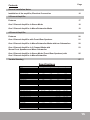
Contents
General Installation Notes
Installation of the amplifier, Electrical Connection
2-Channel Amplifier
Features
One 2 Channel Amplifier in Stereo Mode
One 2 Channel Amplifier in Mono/Subwoofer Mode
4-Channel Amplifier
Features
One 4 Channel Amplifier with Front-/Rear Speakers
One 4 Channel Amplifier in Mono/Subwoofer Mode with two Subwoofers
One 4 Channel Amplifier in 3 Channel Mode with
Stereo Front Speakers and Mono Subwoofer
One 4 Channel Amplifier in Stereo Mode (Front-/Rear Speakers) with
One 2 Channel Amplifier in Mono/Subwoofer
Trouble Shooting
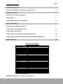
Channels
Output Power Ratings at 14.4 Volts
WWatts at 4 Ohm load - RMS / MAX.
WWatts at 2 Ohm load - RMS / MAX.
Output Power Ratings at 14.4 Volts bridged
WWatts at 4 Ohm load - RMS
WWatts at 4 Ohm load - MAX.
Frequency response -3dB
Damping factor
Signal to noise ratio
Channel seperation
THD & N
Input Gain Control
Input Impedance
Crossover Channel 1 & 2
Full/Lowpass/Highpass
Variable Highpass Crossover 12 dB
Variable Lowpass Crossover 12 dB
BassBoost Control at 45Hz
Crossover Channel 3 & 4
Full/Lowpass/Highpass
Variable Highpass Crossover 12 dB
Variable Lowpass Crossover 12 dB
BassBoost Control at 45Hz
RCA Line Outputs
High Level Inputs
Fuses
Heatsink size in mm
Width x Height
Length
GTS-2175
2
2 x 110 / 175
2 x 175 / 350
1 x 350
1 x 700
20Hz - 30kHz
> 150
>90dB
>70dB
0.10 %
0.2 - 4 Volts
47 kOhms
Full/LP/HP
60Hz - 1.2kHz
40Hz - 150Hz
0dB to +12dB
-
-
-
-
Fullrange
5 Pin Plug
2 x 20 Ampere
262 x 52
250
GTS-480
4
4 x 60 / 80
4 x 80 / 160
2 x 160
2 x 320
20Hz - 30kHz
> 150
>90dB
>70dB
0.10 %
0.2 - 4 Volts
47 kOhms
Full/LP/HP
60Hz - 1.2kHz
40Hz - 150Hz
0dB to +12dB
Full/LP/HP
60Hz - 1.2kHz
40Hz - 150Hz
0dB to +12dB
Fullrange
5 Pin Plug x2
2 x 20 Ampere
262 x 52
285
GTS-4125
4
4 x 85 / 125
4 x 125 / 250
2 x 250
2 x 500
20Hz - 30kHz
> 150
>90dB
>70dB
0.10 %
0.2 - 4 Volts
47 kOhms
Full/LP/HP
60Hz - 1.2kHz
40Hz - 150Hz
0dB to +12dB
Full/LP/HP
60Hz - 1.2kHz
40Hz - 150Hz
0dB to +12dB
Fullrange
5 Pin Plug x2
2 x 25 Ampere
262 x 52
320
GTS-280
2
2 x 60 / 80
2 x 80 / 160
1 x 160
1 x 320
20Hz - 30kHz
> 150
>90dB
>70dB
0.10 %
0.2 - 4 Volts
47 kOhms
Full/LP/HP
60Hz - 1.2kHz
40Hz - 150Hz
0dB to +12dB
-
-
-
-
Fullrange
5 Pin Plug
2 x 15 Ampere
251 x 55
185
Specifications

16
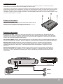
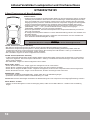
General Installation Notes
The amplifier is generally mounted in the rear trunk area but can be mounted in any convenient area such as beneath a seat. Please
be sure to locate this unit where you have reasonable air circulation and protection from moisture. When considering the mounting
location you should minimize the length of the power and speaker leads. Minimizing both leads will yield a more reliable installation.It
is also important to ensure that the heat sink fins are not against a panel or a surface, preventing air circulation. Do not install the
amplifier on a subwoofer box or on vibrating parts of the vehicle, since the vibrations can cause damage to the amplifiers electrical
components.
Installation of the amplifier
Mark the location for the mounting screw holes by using the amplifier as a template.
Drill holes at the marked locations and firmly fasten the amplifier in place with the
mounting screws supplied in the accessory kit.
Before drilling or cutting any holes, investigate the layout of your automobile thoroughly:
Take care when working near the gas lines or hydraulic lines and electrical wiring.
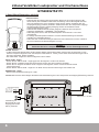
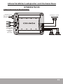
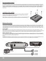
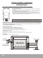
Electrical Connection
Ground (GND)
This wire is the electrical ground and must be fastened securely to the vehicle chassis. The best method is to use a threading sheet
metal screw since the threads cut into bare metal. Ensure that all paint or other insulation is remove from around the hole area, and
using self tapping screw, securely affix the bare wire ends to the vehicle chassis. Use as short a piece of cable as possible - use the
same gauge as was used for the +12V cable. Make sure that the connection is safe, a loose connection may result in amplifier noise
and fault condition.
Remote (REM)
Many radios or other music sources have an output terminal for connection of the remote turn-on of the power amplifier. If a radio
doesn't have a remote turn-on feature, then you can use the antenna relay wire, which activates the antenna motor. Please note, if the
power antenna retracts when the radio is operating, then you cannot use the antenna relay wire to operate the remote turn-on.
Batterie Connection (+12V)
This wire is usually connected directly to the positive battery terminal. Ensure that the + power supply wire is fused via an assigned
fuse in line with the + power supply wire. Please use a sufficient gauge for the installed amplifiers (16-25 mm² ). This connection must
be completed using spade lug with insulating sleeve.
Fuses
The integrated amplifier fuses protect the units from short circuit and overload. The fuse rating is for 4 Ohm loads (impedance) of the
speakers, for 2 Ohm loads the fuses may have to get increased by up to 50% in case of higher power consumption.
CHASSIS
GROUND
CHASSIS
GROUND
REMOTE
BATTERY
FUSE
FU SE
GND REM 12V
POWER INPUT

17
LINE LEVEL
INPUT
LEVEL
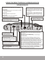
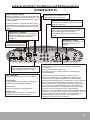
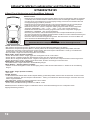
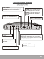
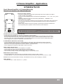
2 Channel Amplifier - Features
GTS280/GTS2175
FILTER - SWITCH
This switch will route the output of the full range (FLAT),
or a low pass (LOW PASS), or the output of the high pass
(HIGH PASS) filter to the internal power amplifier
INPUT LEVEL
This allows you to match the amplifier input
sensitivity to the output level of the source (head
unit)
OUTPUT
Provides a full range line level (RCA) output
that allows the use of additional amplifiers
LINE LEVEL - INPUT
Accepts line level (RCA) inputs from
0.2 to 4 Volts
HI INPUT
Accepts speaker level inputs from
head units that do not have line level
(RCA) outputs
POWER - LED
It indicates amplifier has turn
on signal
PROTECT - LED
It indicates the fault operation of the amplifier. When the fault
conditions (overload, excessive heat or short circuit of speaker)
arise, the protection curcuit is engaged to protect both the speakers
and the amplifier against damage.
HIGH-/LOWPASS - ADJUST
HIGH PASS - The built in high pass filter is fully
variable from 60Hz to 1200Hz (1.2KHz), with a
rolloff of 12dB/octave
LOW PASS - The built in low pass filter is fully
variable from 40Hz to 150Hz, with a rolloff of
12dB/octave
BASS BOOST
Allows you to adjust the bass boost
from 0dB up to 12dB

18
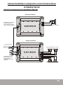
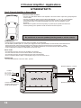
Speakers (Right) 2 - 8 Ohms
Speakers (Left) 2 - 8 Ohms
Connect RCA cable from
head-unit with RCA input
(LINE LEVEL INPUT).
L R
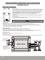
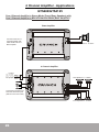
2 Channel Amplifier - Applications
GTS280/GTS2175
One 2 Channel Amplifier in Stereo Mode
Interconnect cable checklist:
• Connect the LINE LEVEL INPUT of the amplifier to the head unit line output with good quality RCA
to RCA cables.
• Connect the speakers with the terminal block (SPEAKERS/ + L - and + R -) of the amplifier.
• The minimum final speaker impedance must not be below 2 Ohm per channel. Too low
speaker loads result in too high heat dissipation and may cause the amplifier run into
protection.
• Please observe speaker channel and polarity as printed by the speaker terminal block.
Incorrect phasing of the speakers results in total loss of bass response.
•
•
•
•
Caution
Be careful not to connect speaker (-) to the ground or vehicle chassis.
FILTER SELECT
• If larger than 20 cm speakers are used, the FLAT position is recommended.
• For all smaller speakers (Ø8.7cm - Ø16cm) the Highpass-Position (HIGH PASS) is recommended, which eliminates the
lowest frequencies and protects the speakers from damage. Set the crossover-frequency between 60Hz - 150Hz,
depending of the size of the installed speakers. The Highpass adjustment can be done with the HIGH PASS control.
• In this configuration example the LOW PASS control is not used.
INPUT LEVEL
• Turn the INPUT LEVEL control on the amplifier to 4V position.
• Turn the head unit volume control to about 80-90% of its full setting.
• Turn the INPUT LEVEL control clockwise until you hear some distortion.
• Then turn back the INPUT LEVEL control slightly until you can hear clean sound.
BASS BOOST
• Turn the BASS BOOST control into “0dB” - position.
•
•
L RL R
Green: Left Speaker -
White: Left Speaker +
Black: Ground
Brown: Right Speaker +
Gray: Right Speaker -
HI INPUT

19
2 Channel Amplifier - Applications
GTS280/GTS2175
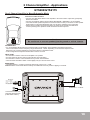
L R
Connect RCA cable from
head-unit with RCA input
(LINE LEVEL INPUT).
Subwoofer 4 - 8 Ohms
One 2 Channel Amplifier in Mono/Subwoofer Mode
FILTER SELECT
• In 1 Channel/Mono-Mode select the Lowpass-Position (LOW PASS), which eliminates the higher frequencies.
The recommended crossover frequency ranges between 60 - 100Hz, depending on the size and response of the
Subwoofer. The Lowpass adjustment can be done with the LOW PASS control.
• In this configuration example the HIGH PASS control is not used.
INPUT LEVEL
• Turn the INPUT LEVEL control on the amplifier to 4V position.
• Turn the head unit volume control to about 80-90% of its full setting.
• Turn the INPUT LEVEL control clockwise until you hear some distortion.
• Then turn back the INPUT LEVEL control slightly until you can hear clean sound.
BASS BOOST
• The BASS BOOST - Control increases the bass level at 45 Hz max. +12dB.
Caution! Please use the Bass-Boost carefully. The additional boost may result in clipping or overload.
•
•
Interconnect cable checklist:
• Connect the LINE LEVEL INPUT of the amplifier to the head unit line output with good quality
RCA to RCA cables.
• Connect the speakers with the terminal block (SPEAKERS/ + BRIDGED -) of the amplifier.
• The minimum final speaker impedance must not be below 2 Ohm per channel. Too low speaker
loads result in too high heat dissipation and may cause the amplifier run into protection.
• Please observe speaker channel and polarity as printed by the speaker terminal block.
Incorrect phasing of the speakers results in total loss of bass response.
•
•
•
Caution
Be careful not to connect speaker (-) to the ground or vehicle chassis.
L RL R
Green: Left Speaker -
White: Left Speaker +
Black: Ground
Brown: Right Speaker +
Gray: Right Speaker -
HI INPUT

20
INPUT
LEVEL
INPUT
LEVEL
INPUT
LEVEL
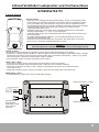
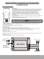
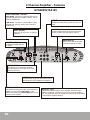
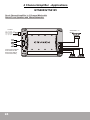
4 Channel Amplifier - Features
GTS480/GTS4125
INPUT
Accepts line level (RCA) inputs from 0.2 to 4
Volts
HIGH-/LOWPASS - ADJUST
HIGH PASS - The built in high pass filter is fully
variable from 60Hz to 1200Hz (1.2KHz), with a
rolloff of 12dB/octave
LOW PASS - The built in low pass filter is fully
variable from 40Hz to 150Hz, with a rolloff of
12dB/octave
PROTECT - LED
It indicates the fault operation of the amplifier. When the fault
conditions (overload, excessive heat or short circuit of speaker)
arise, the protection curcuit is engaged to protect both the speakers
and the amplifier against damage.
BASS BOOST
Allows you to adjust the bass
boost from 0dB up to 12dB
INPUT LEVEL
This allows you to match the amplifier
input sensitivity to the output level of the
source (head unit)
OUTPUT
Provides a full range line level (RCA) output
that allows the use of additional amplifiers
INPUT SELECT
Allows you to chose 2 or 4 channel
operations
HI INPUT
Accepts speaker level inputs from head units
that do not have line level (RCA) outputs
POWER - LED
It indicates amplifier has turn
on signal
FILTER - SWITCH
This switch will route the output of the full range
(FLAT), or a low pass (LOW PASS), or the
output of the high pass (HIGH PASS) filter to the
internal power amplifier

21
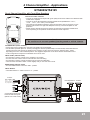
4 Channel Amplifier - Applications
GTS480/GTS4125
Connect RCA outputs from
head-unit with RCA inputs
(INPUT CH1/2 and CH3/4).
One 4 Channel Amplifier with Front-/Rear Speakers
Interconnect cable checklist:
• Connect the head unit line outputs with good quality RCA to RCA cables to the INPUTCH1&2 /
CH3&4 of the amplifier.
• Connect the Front-/Rear Speakers with the terminal blocks (SPEAKERS / + CH1 -,
+ CH2 -, + CH3 -, and + CH4 -) of the amplifier.
• The minimum final speaker impedance must not be below 2 Ohm per channel. Too low
speaker loads result in too high heat dissipation and may cause the amplifier run into
protection.
• Please observe speaker channel and polarity as printed by the speaker terminal block.
Incorrect phasing of the speakers results in total loss of bass response.
•
•
•
•
•
FILTER SELECT (CH1/2 & CH3/4)
• If larger than 20 cm speakers are used, the FLAT position is recommended.
• For all smaller speakers (Ø8.7cm - Ø16cm) the Highpass-Position (HIGH PASS) is recommended, which eliminates the
lowest frequencies and protects the speakers from damage. Set the crossover-frequency between 60Hz - 150Hz,
depending of the size of the installed speakers. The Highpass adjustment can be done with the HIGH PASS control.
• In this configuration example the LOW PASS control is not used.
INPUT LEVEL (CH1/2 & CH3/4)
• Turn the INPUT LEVEL controls on the amplifier to 4V position.
• Turn the head unit volume control to about 80-90% of its full setting.
• Turn the INPUT LEVEL controls clockwise until you hear some distortion.
• Then turn back the INPUT LEVEL controls slightly until you can hear clean sound.
BASS BOOST (CH1/2 & CH3/4)
• Turn the BASS BOOST control into “0dB” - position.
INPUT SELECT
• The INPUT SELECT - switch must be in “4” - position.
•
•
Caution
Be careful not to connect speaker (-) to the ground or vehicle chassis.
L RL R
Rear-Speakers 2 - 8 Ohms
Front-Speakers 2 - 8 Ohms
Green: Left Speaker -
White: Left Speaker +
Black: Ground
Brown: Right Speaker +
Gray: Right Speaker -
HI INPUT

22
4 Channel Amplifier - Applications
GTS480/GTS4125
One 4 Channel Amplifier in Mono/Subwoofer Mode with two Subwoofers
FILTER SELECT (CH1/2 & CH3/4)
• In Mono/Subwoofer-Mode select the Lowpass-Position (LOW PASS), which eliminates the higher frequencies. The recommended
crossover frequency ranges between 60 - 100Hz, depending on the size and response of the Subwoofers. The Lowpass adjustment
can be done with the LOW PASS control.
• In this configuration example the HIGH PASS control is not used.
INPUT LEVEL (CH1/2 & CH3/4)
• Turn the INPUT LEVEL controls on the amplifier to 4V position.
• Turn the head unit volume control to about 80-90% of its full setting.
• Turn the INPUT LEVEL controls clockwise until you hear some distortion.
• Then turn back the INPUT LEVEL controls slightly until you can hear clean sound.
BASS BOOST (CH1/2 & CH3/4)
• The BASS BOOST - Control increases the bass level at 45 Hz max. +12dB.
Caution! Please use the Bass-Boost carefully. The additional boost may result in clipping or overload.
INPUT SELECT
• The INPUT SELECT - switch must be in “2” - position.
•
•
Connect RCA outputs
from head-unit with RCA
inputs (INPUT CH1/2).
Caution
Be careful not to connect speaker (-) to the ground or vehicle chassis.
Interconnect cable checklist:
• Connect the head unit line outputs with good quality RCA to RCA cables to the INPUT CH1&2 of
the amplifier.
• Connect the Subwoofers with the terminal blocks (SPEAKERS / + BRIDGED - from Channel 1&2
and + BRIDGED - from Channel 3&4) of the amplifier.
• The minimum final speaker impedance must not be below 4 Ohm per channel pair. Too low
speaker loads result in too high heat dissipation and may cause the amplifier run into protection.
• Please observe speaker channel and polarity as printed by the speaker terminal block. Incorrect
phasing of the speakers results in total loss of bass response.
•
•
•
•
L RL R
Subwoofer 4 - 8 Ohms
Subwoofer 4 - 8 OhmSubwoofer 4 - 8 Ohms
Green: Left Speaker -
White: Left Speaker +
Black: Ground
Brown: Right Speaker +
Gray: Right Speaker -
HI INPUT

23
4 Channel Amplifier - Applications
GTS480/GTS4125
One 4 Channel Amplifier in 3 Channel Mode with
Stereo Front Speakers and Mono/Subwoofer
Interconnect cable checklist:
• Connect the head unit line outputs with good quality RCA to RCA cables to the INPUT
CH1&2 / CH3&4 of the amplifier.
• Connect the Front Speakers with the terminal block (SPEAKERS / + CH1 - and + CH2 -) of the
amplifier.
• Connect the Subwoofer with the terminal block (SPEAKERS / + BRIDGED - from
Channel 3&4) of the amplifier.
• The minimum final speaker impedance must not be below 2 Ohms Stereo and 4 Ohms Mono.
Too low speaker loads result in too high heat dissipation and may cause the amplifier run
into protection.
• Please observe speaker channel and polarity as printed by the speaker terminal block.
Incorrect phasing of the speakers results in total loss of bass response.
•
•
•
•
•
•
Caution
Be careful not to connect speaker (-) to the ground or vehicle chassis.
FILTER SELECT (Front Speakers Channel 1&2)
• If larger than 20 cm speakers are used, the FLAT position is recommended.
• For all smaller speakers (Ø8.7cm - Ø16cm) the Highpass-Position (HIGH PASS) is recommended, which eliminates
the lowest frequencies and protects the speakers from damage. Set the crossover-frequency between 60Hz - 150Hz,
depending of the size of the installed speakers. The Highpass adjustment can be done with the HIGH PASS control.
• In this configuration example the LOW PASS control is not used.
X-OVER SELECT (Subwoofer Channel 3&4)
• In Mono/Subwoofer-Mode select the Lowpass-Position (LOW PASS), which eliminates the higher frequencies.
The recommended crossover frequency ranges between 60 - 100Hz, depending on the size and response of the
Subwoofer. The Lowpass adjustment can be done with the LOW PASS control.
• In this configuration example the HIGH PASS control is not used.
INPUT LEVEL (CH1/2 & CH3/4)
• Turn the INPUT LEVEL controls on the amplifier to 4V position.
• Turn the head unit volume control to about 80-90% of its full setting.
• Turn the INPUT LEVEL controls clockwise until you hear some distortion.
• Then turn back the INPUT LEVEL controls slightly until you can hear clean sound.
BASS BOOST (CH1/2 & CH3/4)
• Turn the BASS BOOST control from the Front Speakers (Channel 1&2) into “0dB” - position.
• The BASS BOOST - Control from the Subwoofer (Channel 3&4) increases the bass level at 45 Hz max. +12dB.
Caution! Please use the Bass-Boost carefully. The additional boost may result in clipping or overload.
INPUT SELECT
• The INPUT SELECT - switch must be in “4” - position.
•
•
•
•
L RL R

24
4 Channel Amplifier - Applications
GTS480/GTS4125
One 4 Channel Amplifier in 3 Channel Mode with
Stereo Front Speakers and Mono/Subwoofer
Connect RCA outputs
from head-unit with
RCA inputs (INPUT
CH1/2 and CH3/4).
Front-Speakers 2 - 8 Ohms
Subwoofer 4 - 8
Ohms
Green: Left Speaker -
White: Left Speaker +
Black: Ground
Brown: Right Speaker +
Gray: Right Speaker -
HI INPUT

25
4 Channel Amplifier - Applications
GTS480/GTS4125
One 4 Channel Amplifier in Stereo Mode (Front-/Rear- Speakers) with
One 2 Channel Amplifier in Mono/Subwoofer Mode (Bass Amplifier)
Interconnect cable checklist:
• Connect the INPUT of the 4 Channel Amplifier to the head unit line outputs with good quality
RCA to RCA cables.
• Connect the OUTPUT of the 4 Channel Amplifier with the LINE LEVEL INPUT of the designated
Bass Amplifier (2 Channel Amplifier) with a further RCA cable.
• Connect the Front-/Rear Speakers with the terminal blocks (SPEAKERS / + CH1 -, +
CH2 -, + CH3 - and + CH4 -) of the 4 Channel Amplifier.
• Connect the Subwoofer with the terminal block (SPEAKERS / + BRIDGED -) of the
designated Bass Amplifier (2 Channel Amplifier).
• The minimum final speaker impedance must not be below 2 Ohms for the 4 Channel Amplifier,
the total impedance of the Subwoofer(s) must not be below 4 Ohms. Too low speaker loads
result in too high heat dissipation and cause the amplifier run into protection.
• Incorrect polarity of the speakers results in total loss of bass response.
•
•
•
•
•
•
Caution
Be careful not to connect speaker (-) to the ground or vehicle chassis.
Control settings of the 4 Channel Amplifier:
FILTER SELECT (CH1/2 & CH3/4)
• If larger than 20 cm speakers are used, the FLAT position is recommended.
• For all smaller speakers (Ø8.7cm - Ø16cm) the Highpass-Position (HIGH PASS) is recommended, which eliminates the lowest
frequencies and protects the speakers from damage. Set the crossover-frequency between 60Hz - 150Hz, depending of the size of
the installed speakers. The Highpass adjustment can be done with the HIGH PASS control.
• In this configuration example the LOW PASS control is not used.
INPUT LEVEL (CH1/2 & CH3/4)
• Turn the INPUT LEVEL controls on the amplifier to 4V position.
• Turn the head unit volume control to about 80-90% of its full setting.
• Turn the INPUT LEVEL controls clockwise until you hear some distortion.
• Then turn back the INPUT LEVEL controls slightly until you can hear clean sound.
BASS BOOST (CH1/2 & CH3/4)
• Turn the BASS BOOST control into “0dB” - position.
INPUT SELECT
• The INPUT SELECT - switch must be in “4” - position.
Control settings of the Bass Amplifier (2 Channel Amplifier):
FILTER SELECT
• In 1 Channel/Mono-Mode select the Lowpass-Position (LOW PASS), which eliminates the higher frequencies. The recommended
crossover frequency ranges between 60 - 100Hz, depending on the size and response of the Subwoofer. The Lowpass adjustment
can be done with the LOW PASS control. In this configuration example the HIGH PASS control is not used.
INPUT LEVEL
• see descriptions for 4 Channel Amplifier above
BASS BOOST
• The BASS BOOST - Control increases the bass level at 45 Hz max. +12dB.
Caution! Please use the Bass-Boost carefully. The additional boost may result in clipping or overload.
•
•
•
•
L RL R
L RL R

26
4 Channel Amplifier - Applications
GTS480/GTS4125
One 4 Channel Amplifier in Stereo Mode (Front-/Rear- Speakers) with
One 2 Channel Amplifier in Mono/Subwoofer Mode (Bass Amplifier)
4 Channel Amplifier
Bass Amplifier
L R
Subwoofer 4 - 8 Ohms
Connect RCA outputs from
head-unit with RCA inputs
(INPUT CH1/2 and CH3/4).
Connect OUTPUT of 4
Channel Amplifier with
LINE LEVEL INPUT of
Bass Amplifier.
Rear Speakers 2 - 8 Ohms
Front-Speakers 2 - 8 Ohms
Green: Left Speaker -
White: Left Speaker +
Black: Ground
Brown: Right Speaker +
Gray: Right Speaker -
HI INPUT

27
System does not turn on
1. Check all fuses.
2. Check all connections.
3. Measure the +12 volt and remote turn on voltages at the amplifier terminals. If these are non existent or low,
take voltage measurements at fuse holders, distribution blocks, the head unit’s +12 volt and remote leads
to localize the problem.
Noise problems
1. Check the speaker wiring.
2. Speakers are damaged.
No Signal at Channels
1. Set Balance and Fader from head unit on Zero-Position.
2. Check wiring (Amplifier,Speakers).
3. Speakers are damaged.
Hiss or white noise
1. Speakers are overload.
2. High levels of white noise usually occurs when amplifier level controls are turned up too high - readjust according to the procedures in
section ”Setting up systems after installation for best performance.”
3. Another major problem that can cause excessive hiss, is a noisy head unit - unplug the amplifier input RCA cables, and if the hiss level
reduces, the source unit is at fault.
No Stereo-Sound or Low Output
1. Check speaker wiring (-and+).
Amplifier Protection-Mode (red LED is illuminated)
1. Speaker cabels are shorted
2. Inadequate cooling - relocate or remount to provide better natural airflow over the fins.
Driving high power levels into low impedances - back off on the volume control, and/or make sure you are not loading the amplifier with
less than the recommended loudspeaker impedance.
3. Make sure that the battery voltage, as measured at the amplifier’s +12 volt and ground terminals, is 11 volts or more.
2.
2.
2.
2.
2.
2.
Electrical interference
The inside of an automobile is a very hostile electrical environment. The multitude of electrical systems, such as the ignition system, alternator,
fuel pumps, air conditioners to mention just a few, create radiated electrical fields, as well as noise on the +12 volt supply and ground.
Remember to isolate the problem - first unplug amplifier input RCAcables, if the noise is still present, check the speaker leads, if not, plug the
RCA’s back, and investigate the source driving the amplifier, one component at a time.
A ticking or whine that changes with engine RPM:
1. This problem could be caused by radiation pickup of RCA cables too near to a fuel pump or a distributor, for instance, - relocate cables.
2. Check that the head unit ground is connected straight to the vehicle´s chassis, and does not use factory wiring for ground.
3. Try to supply the head unit with a clean +12 volt supply directly from the battery +, instead of using a supply from the in dash wiring/fusebox.
This type of noise can be more difficult to pinpoint, but is usually caused by some kind of instability, causing oscillations in the system.
A constant whine:
1. Check all connections, especially for good grounds.
2. Make sure that no speaker leads are shorting to exposed metal on the vehicle´s chassis.
3. RCA cables are notorious for their problematic nature, so check that these are good qulity cables, in particular the shield connections.
2.
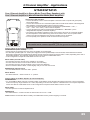
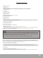
Trouble Shooting
Caution!
In your amplifier there are protection circuits integrated. Short Circuit Protection engaged: The amplifier will turn off and try
to come back on immediately. Then there is an operation fault the PROTECTION LED lights up. If this is the case, check
your speakers and wiring for low impedance and short circuits.Thermal Protection engaged: The amplifier will turn off and
several minutes later will come back on. In this case, ensure that there is nothing blocking the normal convective airflow
of the amplifier. No obstruction should be within 2" of the amplifier on all sides.
NOTE: Low battery voltage will cause the amplifier to run warmer and possibly damage the amplifier.
Page is loading ...
-
 1
1
-
 2
2
-
 3
3
-
 4
4
-
 5
5
-
 6
6
-
 7
7
-
 8
8
-
 9
9
-
 10
10
-
 11
11
-
 12
12
-
 13
13
-
 14
14
-
 15
15
-
 16
16
-
 17
17
-
 18
18
-
 19
19
-
 20
20
-
 21
21
-
 22
22
-
 23
23
-
 24
24
-
 25
25
-
 26
26
-
 27
27
-
 28
28


Crunch GTS 280 Owner's manual
- Category
- Car media receivers
- Type
- Owner's manual
Ask a question and I''ll find the answer in the document
Finding information in a document is now easier with AI
in other languages
- Deutsch: Crunch GTS 280 Bedienungsanleitung
Related papers
-
Crunch gp 1000 4 Owner's manual
-
Crunch GTR 640.4 Owner's manual
-
Crunch GTS1100 Owner's manual
-
-
-
-
-
Crunch GTO4120 User manual
-
-
Crunch GPX1000.4 Owner's manual
Other documents
-
Pyle PDA 4400 Owner's manual
-
Audio Design Signum SX-4120 Owner's manual
-
Audio Pro Ace-bass User manual
-
ESX QM500.4 Owner's manual
-
Renegade REN1400 Owner's manual
-
Renegade REN 1100 S User manual
-
Quantum QS-TWO-ISO Owner's manual
-
MB QUART ZUR5.25IC Installation guide
-
Hifonics TXI6400 Owner's manual
-
Hifonics TRITON I Owner's manual