AC Tool Supply 005747-0 (XG8000E) Owner's manual

Category
Power generators
Type
Owner's manual
introduction.............................................................1
Readthis iVlanualThoroughly.................................1
Safety Rules...........................................................1
StandardsIndex.............................................................3
Generalinformation................................................4
1.1 Unpacking......................................................................4
1.1.1 AccessoryBox..................................................4
1.2 Assembly.......................................................................4
1.2.1 AssemblingtheWheelKitand FrameFoot..........4
Operation................................................................5
2.1 Knowthe Generator.......................................................5
2.1.1 BatteryConnection(XG7000E& XG8000E).......6
2.2 Hourmeter......................................................................6
2.3 CordSetsand ConnectionPlugs....................................6
2.3.1 120 VAC,20 Amp, GFCIDuplexReceptacle.......6
2.3.2 120/240 VAC,30 Amp Receptacle.....................6
2.4 How to Usethe Generator..............................................7
2.4.1 SystemGround..................................................7
2.4.2 GroundingtheGenerator....................................7
2.4.3 Neutralto FrameGrounding...............................8
2.4.4 ConnectingElectricalLoads...............................8
2.5 Don't Overloadthe Generator..........................................8
2.6 WattageReferenceGuide...............................................8
2.7 BeforeStartingthe Generator.........................................9
2.7.1 AddingEngineOil ..............................................9
2.7.2 AddingGasoline.................................................9
2.8 ToStartthe Engine.......................................................10
2.8.1 Manual(Recoil)Starting..................................10
2.8.2 ElectricStarting (XG7000E& XG8000E)..........11
2.9 Stoppingthe Engine.....................................................11
2.10 Low Oil PressureShutdownSystem.............................11
2.10.1 Restarting........................................................11
2.11 Charginga Battery.......................................................11
Maintenance.........................................................11
3.1 MaintenanceSchedule.................................................11
3.2 ProductSpecifications..................................................11
3.2.1 GeneratorSpecifications..................................11
3.2.2 EngineSpecifications.......................................12
3.2.3 EmissionsInformation.....................................12
3.3 GeneralRecommendations...........................................12
3.3.1 GeneratorMaintenance....................................12
3.3.2 ToCleanthe Generator.....................................13
3.3.3 EngineMaintenance.........................................13
3.3.4 CheckingOilLevel...........................................13
3.3.5 Changingthe Oiland Oil Filter..........................13
3.3.6 Replacingthe SparkPlug.................................13
3.4 ServiceAir Cleaner.......................................................13
3.5 CleanSparkArrestorScreen.........................................14
3.6 General........................................................................14
3.7 LongTermStorage.......................................................14
3.8 OtherStorageTips.......................................................15
BatteryService.....................................................15
4.1 BatteryReplacement(XG7000E& XG8000E)...............15
Troubleshooting....................................................16
5.1 TroubleshootingGuide..................................................16
Notes....................................................................17
Warranty...............................................................18
iNTRODUCTiON
Thankyou for purchasingthis modelby GeneracPowerSystems,
Inc. This model is a compact, high performance, air-cooled,
engine driven generatordesigned to supply electrical power to
operateelectrical loads where no utility power is availableor in
placeof utility dueto a poweroutage.
BEADTHiSMANUALTHOROUGHLY
If any portion of this manual is not understood, contact the
nearest Authorized Dealerfor starting, operating and servicing
procedures.
The operator is responsible for proper and safe use of the
equipment.We strongly recommendthat the operator read this
manualandthoroughlyunderstandall instructionsbeforeusingthe
equipment.Wealsostronglyrecommendinstructingotherusersto
properlystart andoperatethe unit.This preparesthem ifthey need
to operatetheequipmentin an emergency.
Thegeneratorcan operatesafely,efficiently andreliablyonly if it
is properlylocated,operatedand maintained.Beforeoperatingor
servicingthe generator:
Becomefamiliar with and strictly adhereto all local, stateand
nationalcodes and regulations.
Study all safety warnings in this manual and on the product
carefully.
Becomefamiliar with this manualandthe unit beforeuse.
Themanufacturercannot anticipateevery possible circumstance
that might involvea hazard.Thewarnings in this manual,andon
tags and decals affixedto the unit are,therefore,not all inclusive.
If usinga procedure,work method or operatingtechniquethatthe
manufacturerdoes not specifically recommend,ensurethat it is
safe for others. Also make sure the procedure,work method or
operatingtechniqueutilizeddoes not renderthe generatorunsafe.
THE INFORMATIONCONTAINEDHEREIN WAS BASED ON
MACHINESIN PRODUCTIONAT THE TIME OF PUBLICATION.
GENERACRESERVESTHERIGHTTOMODIFYTHISMANUALAT
ANYTIME.
SAFETYRULES
Throughoutthis publication,and on tags and decals affixedto the
generator,DANGER,WARNING,CAUTIONand NOTEblocks are
usedto alert personnelto special instructionsabout a particular
operation that may be hazardous if performed incorrectly or
carelessly. Observe them carefully. Their definitions are as
follows:
iNDICATESA HAZARDOUSSiTUATiONORACTIONWHICH,IF
NOTAVOIDED,WiLLRESULTiN DEATHORSERIOUSiNJURY.
Indicatesa hazardoussituationor actionwhich,ifnot
avoided, couldresultin deathor seriousinjury.
_CAUTION!
Indicatesa hazardoussituationor actionwhich,if not
avoided, couldresultin minoror moderateinjury.
NOTE:
Notescontainadditionalinformation importanttoa procedure
and will be found within the regular text bodyof this manual.
These safety warnings cannot eliminate the hazards that they
indicate. Common sense and strict compliancewith the special
instructionswhileperforming theaction or serviceareessentialto
preventingaccidents.
Four commonly used safety symbols accompany the DANGER,
WARNINGand CAUTIONblocks. The type of information each
indicatesis asfollows:
,_This symbol points out important safety
information that, if not followed, could
endanger personal safety and/or property of
others.
This symbol points out potential explosion
hazard.
This symbol points out potential fire hazard.
This symbol points out potential electrical
shock hazard.
GENERAL HAZARDS
Neveroperatein an enclosedareaor indoors.
For safety reasons, the manufacturer recommends that the
maintenanceof this equipmentis carried out by an Authorized
Dealer.Inspectthe generatorregularly,and contactthe nearest
AuthorizedDealerfor parts needingrepairor replacement.
Operategeneratoronly onlevelsurfacesandwhereit will notbe
exposedto excessivemoisture,dirt, dust or corrosivevapors.
Keep hands, feet, clothing, etc., away from drive belts, fans,
and othermoving parts. Neverremoveany fan guardor shield
whilethe unit isoperating.
Certain parts of the generator get extremely hot during
operation. Keep clear of the generator until it has cooled to
avoidsevereburns.
Do NOToperategeneratorinthe rain.
Do not alter the construction of the generator or change
controlswhich might createan unsafeoperatingcondition.
Never start or stop the unit with electrical loads connected
to receptaclesAND with connecteddevicesturned ON. Start
the engine and let it stabilize before connecting electrical
loads. Disconnectall electricalloads beforeshutting downthe
generator.
Do notinsert objectsthrough unit's cooling slots.
When working on this equipment, remain alert at all times.
Never work on the equipment when physically or mentally
fatigued.
Neverusethegeneratororanyofitspartsasastep.Stepping
ontheunitcanstressandbreakparts,andmayresultin
dangerousoperatingconditionsfromleakingexhaustgases,
fuelleakage,oilleakage,etc.
Onelectricstartmodels,disconnectthePOSITIVE(+)battery
cablefromtheenginestarterORtheNEGATIVE(-)battery
cablefromthebatteryterminal,whicheveriseasier,before
transportingthegenerator.
NOTE:
Thisgenerator is equipped with a spark arrestor muffler. The
spark arrestor must bemaintained in effectiveworking order
by the owner/operator. In theState of California, a spark
arrestoris requiredby law (Section4442 of the California
PublicResources Code). Otherstates may havesimilar laws.
Federal lawsapply on federallands.
EXHAUST & LOCATIONHAZARDS
Never operate in an enclosed areaor indoors!NEVERuse in
the home,or in partlyenclosedareas suchas garages, even
if doors and windowsare open! ONLYuse outdoors and far
fromopenwindows,doors, vents,andin anareathatwill not
accumulatedeadly exhaust.
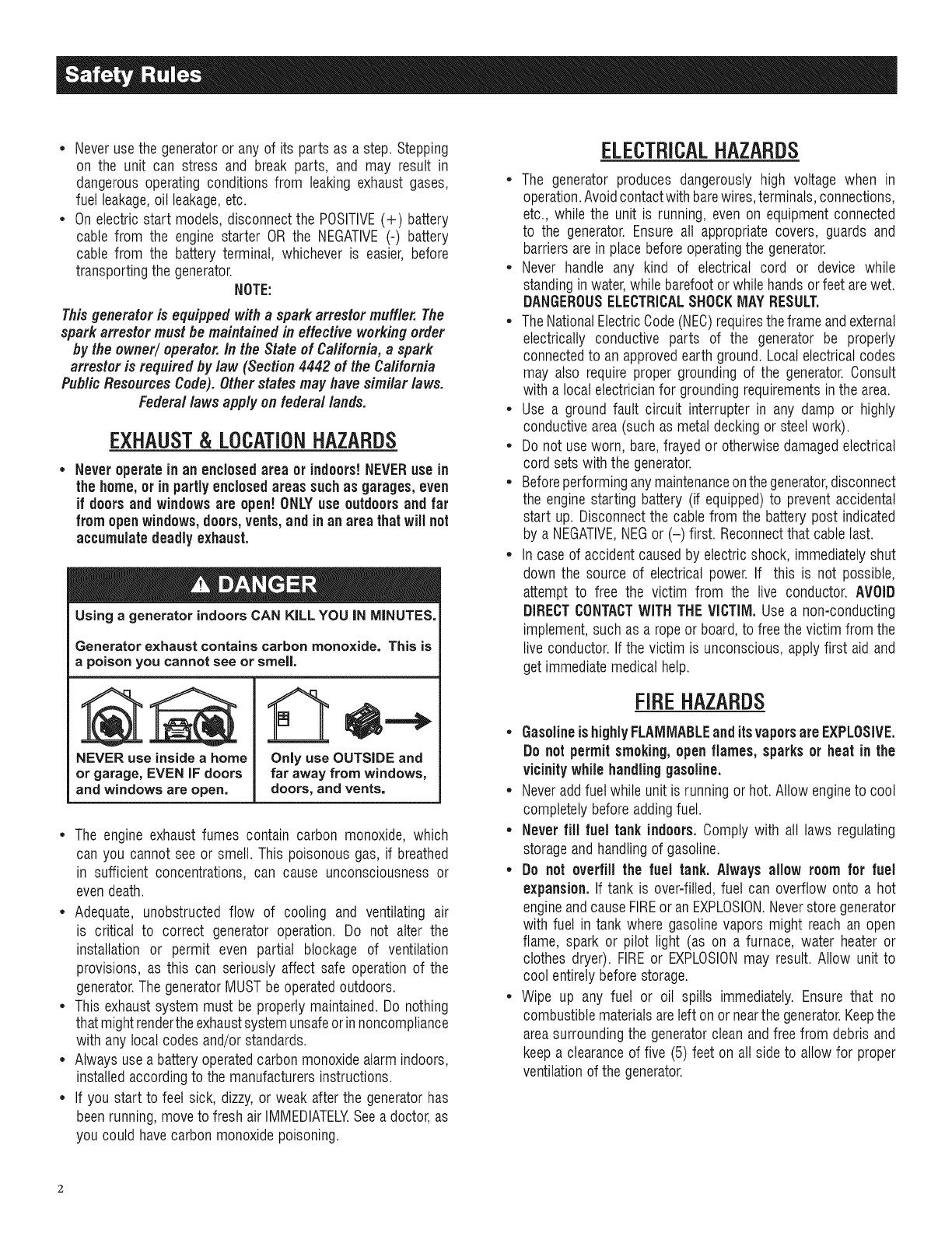
Using a generator indoors CAN KiLL YOU iN MINUTES.
Generator exhaust contains carbon monoxide. This is
a poison you cannot see or smell,
NEVER use insidea home
or garage, EVEN IF doors
and windows are open.
Only use OUTSIDE and
far away from windows,
doors, and vents.
The engine exhaustfumes contain carbon monoxide, which
can you cannot see or smell. This poisonous gas, if breathed
in sufficient concentrations, can cause unconsciousnessor
evendeath.
Adequate, unobstructed flow of cooling and ventilating air
is critical to correct generator operation. Do not alter the
installation or permit even partial blockage of ventilation
provisions, as this can seriously affect safe operationof the
generator.ThegeneratorMUSTbeoperatedoutdoors.
This exhaustsystemmust be properlymaintained.Do nothing
that mightrendertheexhaustsystemunsafeorinnoncompliance
with any localcodes and/orstandards.
Alwaysusea batteryoperatedcarbonmonoxidealarmindoors,
installedaccordingto themanufacturersinstructions.
If you start to feet sick, dizzy,or weak after the generatorhas
beenrunning,moveto fresh air IMMEDIATELYSeea doctor,as
you couldhavecarbonmonoxidepoisoning.
ELECTRICALHAZARDS
The generator produces dangerouslyhigh voltage when in
operation.Avoidcontactwith barewires,terminals,connections,
etc., while the unit is running,even on equipmentconnected
to the generator. Ensureall appropriate covers, guards and
barriersarein placebeforeoperatingthegenerator.
Never handle any kind of electrical cord or device while
standinginwater,while barefootorwhile handsor feet arewet.
DANGEROUSELECTRICALSHOCKMAYRESULT.
TheNationalElectricCode(NEC)requirestheframe andexternal
electrically conductive parts of the generator be properly
connectedto an approvedearthground.Local electricalcodes
may also require proper grounding of the generator.Consult
with a localelectricianfor groundingrequirementsinthearea.
Use a groundfault circuit interrupter in any damp or highly
conductivearea(such as metaldecking or steelwork).
Do not useworn, bare,frayed or otherwisedamagedelectrical
cord setswith the generator.
Beforeperforminganymaintenanceonthegenerator,disconnect
the enginestarting battery (if equipped)to prevent accidental
start up. Disconnectthe cablefrom the batterypost indicated
by a NEGATIVE,NEGor (-) first. Reconnectthat cable last.
In caseof accidentcausedby electricshock, immediatelyshut
down the source of electrical power. If this is not possible,
attempt to free the victim from the live conductor. AVOID
DIRECTCONTACTWITHTHEVICTIM, Use a non-conducting
implement,such asa rope or board,to freethevictim from the
live conductor.If the victim is unconscious,applyfirst aid and
getimmediatemedical help.
FIREHAZARDS
GasolineishighlyFLAMMABLEand itsvaporsare EXPLOSIVE.
Do not permitsmoking,open flames, sparksor heat in the
vicinitywhilehandlinggasoline.
Neveraddfuel whileunit isrunning or hot. Allow engineto cool
completelybeforeaddingfuel.
Never fill fuel tank indoors, Comply with all laws regulating
storageand handlingof gasoline.
Do not overfill the fuel tank. Always allow roomfor fuel
expansion. If tank is over=filled,fuel can overflow onto a hot
engineandcauseFIREor an EXPLOSION.Neverstoregenerator
with fuel in tank where gasolinevapors might reach an open
flame, spark or pilot light (as on a furnace, water heateror
clothes dryer). FIREor EXPLOSIONmay result. Allow unit to
cool entirelybeforestorage.
Wipe up any fuel or oil spills immediately.Ensure that no
combustiblematerialsareleft on or nearthegenerator.Keepthe
areasurroundingthe generatorcleanandfree from debrisand
keepa clearanceof five (5) feet on all side to allow for proper
ventilationofthe generator.
* Donot insert objectsthrough unit's coolingslots.
* Do not operate the generatorif connected electrical devices
overheat,ifelectricaloutputis lost,if engineor generatorsparks
or if flamesor smokeare observedwhile unit is running.
* Keepa fire extinguishernearthe generatorat all times.
STAtVDARDS/#DEX
In the absence of pertinent standards, codes, regulations and
laws, the publishedinformation listed below may be used as a
guidelinefor operation of this equipment. Always referencethe
latestrevisionavailablefor the standardslisted.
1. NFPANo. 70, NFPAHANDBOOKOF NATIONALELECTRIC
CODE.
2. Article X, NATIONALBUILDINGCODE,available from the
American InsuranceAssociation, 85 John Street, NewYork,
N.Y.10038.
3. AGRICULTURALWIRINGHANDBOOK,availablefrom the Food
and EnergyCouncil, 909 UniversityAvenue, Columbia, Me
65201.
4. ASAE EP-3634, INSTALLATIONAND MAINTENANCEOF
FARMSTANDBYELECTRICALSYSTEMS,availablefrom the
AmericanSocietyof AgriculturalEngineers,2950 Niles Road,
St. Joseph,MI49085.
MODELNO:
SERIALNO:
Generator Identification
Unit ID
Locations
CALIFORNIAPROPOSiTiON65 WARNING
Engineexhaustand someof its constituentsareknown
tothe Stateof Californiato causecancer,birth defects
and otherreproductiveharm.
CALIFORNIAPROPOSITION65 WARNING
Thisproduct containsor emitschemicalsknownto the
StateofCaliforniato cause cancer,birthdefectsand
otherreproductiveharm.
1.1 UNPACKING
Removeall packagingmaterial.
Removeseparateaccessorybox.
Removecarton off the generator.
1.1.1 ACCESSORYBOX
Checkall contents(Figure1). If anyparts aremissing or damaged
locatean authorizeddealerat 1-888-775-6937.
Contentsinclude:
2-Axle Pins Oil Filter
2- WheelSpacers Air Filter
2- HairPins SparkPlug
2- Wheels SparkPlugWrench
1 - FrameFoot ShopTowel
2 - FrameBolts 2 - FrameWashers
2-Vibration Mounts Oil Funnel
4 - FlangeNuts 12 VoltAdaptorPlugCharger
2 - 1 QuartSAE30 Oil Bottles
Figure 1 - Accessory Boxes
Referto Figure2 and install the wheel kit and frame foot as
follows:
Slidethe AxlePin throughthe Wheel,WheelSpacer(Washer)
andthe Frame.
Installthe Hair Pinto the Axle Pinto securethe wheel. Repeat
forthe oppositeside.
SecuretheVibrationMountsto theFrameFootwith theincluded
locking nuts.
To install the Frame Foot, install the Frame Bolts though the
FrameWashers,Frameand Framefoot. Securewiththelocking
nuts.
Figure 2 - Wheel and Foot Assembly
FOOT
SECUREWHEEL
ANDAXLEWITH
HAIRPIN
1.2 ASSEMBLY
Read entireOwner's Manual beforeattemptingto assemble or
operatethe generator. The generator requiressome assembly
prior to usingit. If problemsarisewhenassemblingthe generator,
pleasecallthe GeneratorHelplineat 1-888-775-6937.
1.2.1 ASSEMBLINGTIlE WHEELKITANDFRAMEFOOT
Thewheelkit is designedto greatly improvethe portability of the
generator.You will needthe following tools to install the wheel
kit: Pliers,1/2" (13mm) wrench and a socket wrench with a 1/2"
(13mm) socket.
NOTE:
The wheel kit is not intendedfor over-the-road use.
FRAME
WASHER
FRAME
BOLT
WHEELSPACER
(WASHER)
SLIDEAXLE
THROUGHWHEEL
ANDWHEEL
SPACER
2.1 KNOWTHEGENERATOR
Read the entire Owner's Manual and Safety Rules before
operatingthisgenerator.
Compare the generator to Figures 3 through 6 to become
familiarizedwith thelocationsof variouscontrolsandadjustments.
Savethis manualfor futurereference.
1. ChokeKnob- Usedwhen startinga coldengine (Pull/Push).
2. EngineSwitch - Controlsthe operationof the generator.On
electric start models the switch is Start/Run/Stop.On recoil
start modelsthe switch is On/Off.
3. FuelShut Off - Valvebetweenfueltank and carburetor.Turn
off and run carburetoroutof fuelfor extendedstorage.
4. PanelLED's- Provideilluminationof the control panelwhile
thegeneratoris operating.
5. 120/240 Volt AC, 30 Amp LockingReceptacle- Supplies
electricalpowerfor the operationof 120 and/or240 VoltAC,
30 Amp, single-phase,60 Hz, electrical lighting, appliance,
tool andmotor loads.
5. 120 Volt AC,20 Amp,GFCiDuplexReceptacle- Supplies
electrical power for the operationof 120 Volt AC, 20 Amp,
single-phase, 60 Hz electrical lighting, appliance, tool and
motor loads. It also provides protection with an Integral
Ground Fault Circuit Interrupter, complete with a press to
"Test"and "Reset"button.
7. Circuit Breakers (AC)- Each20 Amp receptacleis provided
with a push-to-reset circuit breakerto protectthe generator
againstelectricaloverload.
8. Circuit Breakers (AC)- The30 Amp receptacleis protected
with a pair of push-to-reset circuit breakersto protect the
generatoragainstelectricaloverload.
g. PowerBar- Indicatesthe amountof power being usedfrom
thegenerator;each sectionis approximately25%
10. Hourmeter- Providesoperatinghoursfor Service Intervals.
11. Battery Charger input (Electric Start Models) - This
receptacleallowsthecapabilityto rechargethe12 VDCengine
starting battery with the 12 Volt Adaptor Plug Charger.The
batteryisprotectedby a 1.50 Ampin-linefuse which is inside
thecontrol panel.
12. FuelTank- Tankholds9 U.S.gallonsoffuel.
13. FuelGauge- Showsfuel levelintank.
14. Handles - Pivot and retractfor storage. Press the spring-
loadedbuttonto move handles.
15. Oil Fill- Checkoil levelandadd oil here.
18. GroundingLug- Groundthe generatorto an approvedearth
groundhere.See"GroundingtheGenerator"for details.
17. Muffler- Includesthe sparkarrestor andquietsthe engine.
18. Spark Plug Location - The spark plug ignites the Air/Fuel
Mixture(Sidepanelmust be removed).
lg. Engine Oil Filter- Filtersengineoil; seeSection 3.1 for the
properservice intervals.
20. Air Cleaner- Filtersintakeair as it is drawn intothe engine.
21. Oil Drain- Drain valveto remove used oil from the engine
crankcase.
22. Recoil Starter - Useto start enginemanually.
Figure 3 - GeneratorLocations
2 5 8 9 10
3 4 7 8 4
12
13
15
16
2O
11
@
@
17
22
2.1.1 BATTERYCONNECtiONfXG7OOOE&XG8OOOE)
NOTE:
The battery shippedwiththe generator hasbeenfully charged.
A battery may losesomeof itschargewhennot in use for
prolongedperiodsof time. If the battery isunable to crank
the engine, pluginthe 12V chargerincludedinthe accessory
box(see theChargingthe Battery section).RUNNINGTHE
GENERATORDOESNOTCHARGETHEBATTERY.
The positive battery wire was deliberately left detached for
shipping. To operatethe unit, attachthis wire to the terminal on
the startermotor as shown.Do notovertighten.Slidethe attached
rubber bootoverthe starterterminal.SeeFigure4.
Figure4 - Battery Connection
/
/ L_'! / //// /fi BATTERYCABLE_
2.2 HOUBMETEB
The Hourmeter tracks hours of operation for scheduled
maintenance:
Therewilt be a onetime breakin "CHGOIL"messagethatflashes
with the elapsedtime in hoursand tenths after thefirst 30 hours
of operation.
This messagewill actuallybeginflashing at 29 hoursand disable
itself at 31 hours providing a two hourwindow to perform the
service.
Therewill be a subsequent"CHGOIL"messageevery100 hours.
Themessagewill flash one hour beforeand one hour after each
100 hour interval,again providinga two hour window to perform
service.
Every200 hoursthe "SVC"icon on the lower left handcorner of
the display will flash. Themessagewill flashone hourbeforeand
onehourafter each200 hourintervalprovidingatwo hourwindow
to perform service.
Whenthe hour meter is inthe FlashAlert mode, the maintenance
message will always alternate with elapsedtime in hours and
tenths. The hours wilt flash four times, then alternate with the
maintenancemessagefourtimes untilthemeter resetsitself.
* 100 hours- CHGOIL-- OilChangeInterval(Every100 hrs)
* 200 hours- SVC-- Air FilterInterval(Every200 hrs)
2.3 CORDSETSAND CONNECTIONPLUGS
2.3.1 120VAC,20AMP,GFC/DUPLEXRECEPTACLE
This is a 120 Volt outlet protectedagainst overloadby a 20 Amp
push-to-resetcircuitbreaker(Figure5). Useeachsocketto power
120 VoltAC, singlephase,60 Hzelectricalloadsrequiringupto a
combined 2400 watts (2.4 kW) or 20 Amps of current.Use only
high quality,well-insulated, 3-wire grounded cord sets ratedfor
125 Volts at 20 Amps (or greater).
Keep extensioncords as short as possible, preferablyless than
15 feet long, to preventvoltage drop and possibleoverheatingof
wires.
2.3.2 120/240VAC,30AMP RECEPTACLE
Use a NEMAL14-30 plug with this receptacle (rotate to lock!
unlock). Connecta suitable4-wire groundedcord set to the plug
andto thedesiredtoad.Thecordset shouldbe ratedfor 250Volts
ACat 30 Amps (or greater)(Figure5).
Use this receptacleto operate120 Volt AC, 60 Hz, singlephase
loads requiringup to 3600 watts (3.6 kW) of powerat 30 Amps
or 240 VoltAC,60 Hz,singlephaseloadsrequiring6,500 to 8000
watts of power,dependingonthemodel.Theoutletis protectedby
a 30 Ampcircuit breaker.
Figure5 - GeneratorReceptacles
Kin
, a
120 VAC20A
GFCIRECEPTACLE
120/240 VAC30A
RECEPTACLE
2.4 HOW TO USETHEGENERATOR
If thereare any problems operatingthe generator,pleasecall the
generatorhelplineat 1-888-436-3722.
,l_ Never operate in an enclosed area or indoors!
NEVER use in the home, or in partly enclosed
areas such as garages, even if doors and
windows are open! ONLY use outdoors and far
from open windows, doors, vents, and in an
area that will not accumulate deadly exhaust.
,l_The engine exhaust fumes contain carbon
monoxide, which can you cannot see or smell.
This poisonous gas, if breathed insufficient
concentrations, can cause unconsciousness or
even death.
Adequate, unobstructed flow of cooling and
ventilating air is critical to correct generator
operation. Do not alter the installation or permit
even partial blockage of ventilation provisions,
as this can seriously affect safe operation
of the generator. The generator MUST be
operated outdoors.
,l_This exhaust system must be properly
maintained. Do nothing that might render the
exhaust system unsafe or in noncompliance
with any local codes and/or standards.
,l_The manufacturer recommends installing
a battery operated carbon monoxide alarm
indoors, according to the manufacturers
instructions.
Using a generator indoors CAN KILL YOU IN MINUTES.
Generator exhaust contains carbon monoxide. This is
a poison you cannot see or smell.
NEVER use insidea home
or garage, EVEN iF doors
and windows areopen,
Only use OUTSIDE and
far away from windows,
doors, and vents.
2.4.1 SYSTEMGROUND
Thegeneratorhas a system groundthat connectsthe generator
frame components to the ground terminals on the AC output
receptacles. Thesystem groundis bondedto theAC neutralwire
in the generatorcontrol panelvia a jumperwire.
SpecialRequirements
There may be Federalor State OccupationalSafety and Health
Administration(OSHA)regulations,localcodes,or ordinancesthat
applyto the intendeduse ofthe generator.
Pleaseconsult a qualified electrician, electricalinspector, or the
local agencyhavingjurisdiction:
* In some areas, generators are requiredto be registeredwith
local utilitycompanies.
* If the generatoris used at a construction site, there may be
additionalregulationswhich must be observed.
Connectingto aBuilding'sElectricalSystem
Connectionsfor standby power to a building's electricalsystem
must be made by a qualified electrician. The connection must
isolatethe generatorpower from utility power or otheralternative
power sources and must comply with all applicable laws and
electricalcodes.
2.4.2 GROUND/NG TIlE GENERATOR
The National Electrical Code requires that the
frame and external electrically conductive parts
of this generator be properly connected to an
approved earth ground.
Local electrical codes may also require proper grounding of
the unit (Figure6). Forthat purpose,connectinga No.10 AWG
(AmericanWireGauge)strandedcopperwireto the groundinglug
and to an earth=drivencopperor brass groundingrod (electrode)
provides adequateprotection against electrical shock. However,
local codes may vary widely.Consultwith a localelectricianfor
grounding requirements in the area.
Proper groundingof the generatorwill help preventelectrical
shockin theeventof a groundfault conditioninthe generatoror in
connectedelectricaldevices.Propergroundingalsohelpsdissipate
static electricity,which often buildsup in ungroundeddevices.
Figure6 - GeneratorGroundLocation
LOCATION
XG6500& XG7000
GROUNDLOCATION
2.4.3 NEUTRAL70FRAMEGROUNDING
If service work is performed on the alternator,DO NOTdiscard
the white jumper wires from the terminal blockto the alternator
ground, located on the rear bearing carrier. Always make sure
the wires are properlyconnectedbeforeusingthe generatorafter
alternatorservicework is done (Figure7).
Failure to reconnect these wires may create a
potential shock hazard when the generator is
running!
Figure7- NeutraltoFrameGround
NEUTRALTO FRAMEGROUND
XG7000& 8000
DONOTDISCARD
WIREST
DONOTDISCARD
3EWIREST
NEUTRALTO FRAMEGROUNDXG6500
2.4.3 CONNECT/NGELECTR/CALLOADS
DONOTconnect240 Volt loadsto 120 Voltreceptacles.
DONOTconnect3 phaseloadsto the generator.
DONOTconnect50 Hzloadsto the generator.
* Let engine stabilize and warm up for a few minutes after
starting.
* Plug in and turn on the desired 120 or 240 Volt AC, single
phase,60 Hzelectricalloads.
Add up the ratedwatts (or amps) of all loadsto be connected
at one time. This total should no be greaterthan (a) the rated
wattage/amperagecapacity of the generator or (b) circuit
breakerratingofthereceptaclesupplyingthepower.See"Don't
OverloadtheGenerator
2.5 DON'TOVERLOADTHEGENERATOR
Overloadinga generatorin excess of its ratedwattage capacity
can result in damageto the generatorandto connectedelectrical
devices.Observethefollowing to preventoverloadingthe unit:
* Addupthetotal wattageofall electricaldevicesto be connected
at one time. This total should NOT be greater than the
generator'swattagecapacity.
* The ratedwattageof lights can betaken from light bulbs.The
ratedwattageof tools, appliancesand motors can usually be
foundon a datalabelor decalaffixedto the device.
* If the appliance,tool or motor does not give wattage,multiply
voltstimes ampereratingto determinewatts (voltsx amps =
watts).
* Some electric motors, such as induction types, require about
threetimes morewatts of powerfor startingthan for running.
This surge of power lasts only a few seconds when starting
suchmotors. Makesureto allowfor high startingwattagewhen
selectingelectricaldevicesto connectto the generator:
1. Figurethe watts neededto start the largestmotor.
2. Add to that figure the running watts of all other connected
loads.
TheWattageReferenceGuideis providedto assist in determining
how many itemsthegeneratorcan operateatonetime.
NOTE:
All figuresare approximate.See datalabel onappliancefor
wattagerequirements.
2.6 WATTAGEREFERENCEGUIDE
Device................................... RunningWatts
*AirConditioner(12,000Btu).......................... 1700
*AirConditioner(24,000Btu).......................... 3800
*AirConditioner(40,000Btu).......................... 6000
BatteryCharger(20Amp).............................. 500
BeltSander(3").................................... 1000
ChainSaw........................................ 1200
CircularSaw(6-1/2")........................... 800to 1000
*ClothesDryer(Electric)............................. 5750
*ClothesDryer(Gas)................................. 700
*ClothesWasher................................... 1150
CoffeeMaker...................................... 1750
*Compressor(1 HP)................................. 2000
*Compressor(3/4HP)............................... 1800
*Compressor(1/2HP)............................... 1400
CurlingIron......................................... 700
*Dehumidifier....................................... 650
DiscSander(9").................................... 1200
EdgeTrimmer....................................... 500
ElectricBlanket...................................... 400
Electric NailGun.................................... 1200
Electric Range(per element)........................... 1500
Electric Skillet...................................... 1250
*Freezer............................................ 700
*FurnaceFan(3/5 HP) ................................ 875
*GarageDoorOpener............................ 500to 750
HairDryer......................................... 1200
Hand Drill.................................... 250 to 1100
HedgeTrimmer...................................... 450
Impact Wrench...................................... 500
Iron.............................................. 1200
*Jet Pump ......................................... 800
Lawn Mower....................................... 1200
Light Bulb.......................................... 1O0
Microwave Oven............................... 700 to 1000
*Milk Cooler....................................... 1100
OilBurneron Furnace................................. 300
OilFiredSpaceHeater(140,000 Btu) ..................... 400
OilFiredSpaceHeater(85,000 Btu) ...................... 225
OilFiredSpaceHeater(30,000 Btu) ...................... 150
*Paint Sprayer,Airless (1/3 HP) ......................... 600
PaintSprayer,Airless (handheld)......................... 150
Radio......................................... 50 to 200
*Refrigerator........................................ 700
SlowCooker........................................ 200
*SubmersiblePump (1-1/2 HP) ........................ 2800
*SubmersiblePump (1 HP) ........................... 2000
*SubmersiblePump (1/2 HP).......................... 1500
*Sump Pump................................. 800 to 1050
*Table Saw(10") ............................. 1750 to 2000
Television..................................... 200to 500
Toaster..................................... 1000 to 1650
WeedTrimmer ...................................... 500
* Allow 3 times thelistedwatts for starting these devices.
2.7 BEFORESTARTINGTHEGENERATOR
Prior to operating the generator, engine oil and gasoline will need
to be added, as follows:
2,7,1 AD#/NGEflG/NEO/L
All oil should meetminimum American PetroleumInstitute (API)
Service Class SJ, SL or better.Use no special additives. Select
the oil's viscosity grade according to the expected operating
temperature(also seechart).
Above40° F,useSAE30
Below40° Fand downto 10° F,use10W-30
Below10° F,usesynthetic5W-30
,_Any attempt tocrankor startthe enginebeforeit has
been properlyserviced with the recommendedoil may
resultin an enginefailure.
TEMPERATURE IN DEGREES FAHRENHEIT (°F)
=30 =20 ='tO 0 10 20 32 40 55 70+
||||
=30 =20 =10 0 10 20
TEMPERATURE IN DEGREES CELSIUS (°C)
Placegeneratorona levelsurface.
Cleanareaaroundoil fill andremoveoil fill cap.
Slowly fill engine with oil through the oil fill opening until it
reachesthefull mark.Stopfilling occasionallyto checkoil level.
(Engineoil is full when levelis up to the threadsof the oil fill
plug,seeFigure8)
Installoil fill capandfingertighten securely.
Checkengineoil levelbeforestarting eachtimethereafter.
Figure 8 - Off Level
L
--J
FILLCRANKCASETO
THE BOTTOMOFTHESE
-- THREADSWiTHTHE
RECOMMENDED
ENGINEOIL
II
I
2.7,2 ADD/NGGASOLINE
ADO NOTlighta cigaretteor smokewhen filling the fuel
tank.
,_ Neverfiil fuel tankindoors.Neverfiil fuel tankwhen
engineis running or hot.Avoid spillinggasoline on a hot
engine.Allow engineto coolentirelybeforefilling fuel
tank.
Donot overfill the fuel tank.Alwaysleave roomfor fuel
expansion,ifthefuel tankisoverfilled,fuel canoverflow
onto a hot engine and causeFiREor EXPLOSION.Wipe
up anyspilledfuel immediately.
Use regularUNLEADEDgasolinewith the generatorengine.Do
not usepremiumgasoline.Do notmix oil with gasoline.
Do not usegasolinewith morethan 10% alcohol such as E85
or Methanol.
Cleanareaaroundfuelfill cap, removecap.
Slowly addunleadedregulargasolineto fueltank. Fillto bottom
of screenfilter.Be carefulnot to overfill (Figure9).
Installfuel cap andwipe up any spilledgasoline.
Figure g- Fuel Fill Level
DONOTFILL
AB( LIP!
IMPORTANT:It isimportantto preventgumdepositsfrom forming
in fuel system parts such as the carburetor,fuel hose or tank
during storage. Alcohol-blendedfuels (called gasohol, ethanol
or methanol)can attract moisture, which leadsto separationand
formation of acids duringstorage.Acidic gascandamagethefuel
system of an enginewhile in storage.Toavoid engineproblems,
the fuel system should be emptiedbefore storageof 30 days or
longer.Seethe "Storage"section.Neveruseengineor carburetor
cleaner products in the fuel tank as permanent damage may
occur.
2.8 TOSTARTTHEENGINE
Never startor stopenginewithelectricaldevicespluggedinto
the receptacles ANDdevices turnedon.
Unplug all electrical loads from the unit's receptaclesbefore
startingthe engine.
Makesurethe unitis in a levelposition.
Openthefuel shut-off valve (Figure10).
Pull engine CHOKEknob outward to "Full Choke" position
(Figure11).
Figure 10 - Fuel Shut-off Valve
i
2.8.1 MANUAL_ STARTING
Tostartthe generator,putthe on/off switch in the ONposition.
Firmly grasp the recoil handle and pull slowly until increased
resistanceisfelt. Pull rapidlyup and awayto start engine.
When the engine starts, push choke knob to "1/2 Choke"
position untilthe engine runssmoothly and thenfully into the
"Run" position. If enginefalters, pull choke knob back out to
"1/2 Choke"position until the engine runs smoothly and then
to "Run" position.
NOTE:
If enginefires,but doesnot continuetorun, pull chokeknob
to "Furl Choke" and repeatstartinginstructions.
IMPORTANT:Donotoverloadthe generator.Also, do not overload
individual panel receptacles.Theseoutlets are protectedagainst
overload with push-to-reset-type circuit breakers. Read "Don't
OverloadtheGenerator"carefully.
1o
2.8.1 ELECTRICSTARtiNG(XG7OOOE&XGSOOOE)
Tostartthe engine,pressandholdtheStart/Run/Stopswitch in
the "Start" position.Theenginewill crankandattemptto start.
Whenthe enginestarts, releasetheswitch to the run position.
When the engine starts, push choke knob to "1/2 Choke"
position untilthe engine runssmoothly andthenfully in to the
"Run" position. If enginefalters, pull choke knob back out to
"1/2 Choke"position until the engine runs smoothly and then
to "Run" position.
This generatoris also equippedwith a manual recoil starter
which may be usedif the batteryis discharged.
NOTE:
TheengineStart/Run/Stop switch mustbe in the RUN
position whenusingthe manualrecoil starter.
2.9 STOPPINGTHEENGINE
* Shutoffall loads,thenunplugtheelectricalloadsfrom generator
panelreceptacles.Neverstart or stop theenginewith electrical
devicespluggedin andturnedon.
* Let engine run at no-load for several minutes to stabilizethe
internaltemperaturesof engineandgenerator.
, Move Start/Run/Stopor On/Offswitch tothe "Off" position.
* Closefuelvalve.
2.10LOWOILPRESSURESHUTDOWNSYSTEM
Theengineis equippedwith a low oil pressuresensor that shuts
downthe engineautomaticallywhentheoil pressuredropsbelow
5 psi. A delay built into the low oil shutdown system allows oil
pressureto build during starting. The delayallows the engineto
run for about10 secondsbeforesensingoil pressure.If theengine
shutsdown by itselfandthe fueltank hasenoughgasoline,check
engineoil level.
2.10.1RESTARtiNG
Iftrying to restartthe enginewithin 10secondsafterit shutsdown,
the enginemay NOTstart. Thesystem needs5 to 10 secondsto
reset.
If the engine is restartedafter such a shutdown and the low oil
pressurehas not beencorrected,the enginewill run for about10
secondsas describedaboveandthen stop.
2.11CHARGINGTHEBATTERY(XGTOOOE&XG8OOOE)
Do not permit smoking, open flame, sparks
or any other source of heat around a battery.
Wear protective goggles, rubber apron and
rubber gloves when working around a battery.
Battery electrolyte fluid is an extremely
corrosive sulfuric acid solution that can cause
severe burns, if spill occurs flush area with
clear water immediately.
Storage batteries give off explosive hydrogen
gas while recharging. An explosive mixture will
remain around the battery for a long time after
it has been charged. The slightest spark can
ignite the hydrogen and cause an explosion.
Such an explosion can shatter the battery and
cause blindness or other serious injury.
Use batterychargerplugto keepthe batterychargedandready
for use. Batterychargingshouldbe done in a dry location.
1. Plugchargerinto "BatteryChargerInput" jack, locatedon the
control panel.Plugwall receptacleend of the batterycharger
into a 120 VoltACwall outlet.
2. Unplugbatterychargerfromwall outlet andcontrol paneljack
whengeneratoris goingto be in use.
NOTE:
Donot use the battery chargerfor more than 48 hoursat one
charge.
3.1 MAINTENANCESCHEDULE
Follow the calendar intervals. More frequent service is required
whenoperatingin adverseconditionsnotedbelow.
CheckOil Level
ChangeOiland OilFilter:!:
CleanSparkArrestorScreen
ServiceAir Cleaner
ReplaceSparkPlug
$
"k
At EachUse
*Every Season/Every100 Hours
**Every Season/Every200 Hours
EverySeason
Changeoil after first 30 hours of operationthen every season.
Changeoil and oil filter every month when operating underheavy load or in
high temperatures.
Clean more often under dirty or dusty operating conditions. Replaceair
cleanerparts if very dirty.
3.2 PRODUCTSPECIFICATIONS
3.2.1 GENERATORSPEC/F/CATIONS
Model # ............................................................... 005800-0, 005747-0
RatedMax.Power................................................................... 8.0 kW**
SurgePower................................................................................ 10 kW
RatedACVoltage...................................................................... 120/240
RatedMax AC Load
Current@ 240V............................................................. 33.3 Amps**
Current@ 120V............................................................. 66.7 Amps**
RatedFrequency.................................................... 60 Hz@ 3600 RPM
Phase................................................................................ SinglePhase
RatedDCVoltage...................................................................... 12 Volts
BatteryType.................................................................... 10 AH, 12VDC
11
Model # ............................................................... 005797-0, 005798-0
RatedMax.Power................................................................... 7.0 kW**
SurgePower............................................................................. 8.75 kW
RatedACVoltage...................................................................... 120/240
RatedMax ACLoad
Current@ 240V............................................................. 29.2 Amps**
Current@ 120V............................................................. 58.3 Amps**
RatedFrequency.................................................... 60 Hz@ 3600 RPM
Phase................................................................................ SinglePhase
RatedDCVoltage...................................................................... 12 Volts
BatteryType.................................................................... 10 AH, 12VDC
Model # ................................................................................ 885796-0
RatedMax.Power................................................................... 6.5 kW**
SurgePower............................................................................. 8.13 kW
RatedACVoltage...................................................................... 120/240
RatedMax ACLoad
Current@ 240V............................................................. 27.1 Amps**
Current@ 120V............................................................. 54.2 Amps**
RatedFrequency.................................................... 60 Hz@ 3600 RPM
Phase................................................................................ SinglePhase
RatedDCVoltage...................................................................... 12 Volts
** Maximumwattageandcurrentaresubjectto,andlimitedby,suchfactors
asfuelBtucontent,ambienttemperature,altitude,enginecondition,etc..
Maximumpowerdecreasesabout3.5%foreach1,000feetabovesealevel;
andwillalsodecreaseabout1%for each6° C(10° F)above16° C(60° F)
ambienttemperature.
3.2.2 ENGINESPECIFICAtiONS
RatedHorsepower@ 3600 RPM.................................................... 14.5
Displacement............................................................................... 410cc
SparkPlugType................................... ChampionRO14YOor Equivalent
SparkPlug Gap............................................... 0.030 inch or (0.76 mm)
GasolineCapacity............................................................ 9 U.S.gallons
OilType.................................... SeeChart in "AddingEngineOil"Section
OilCapacity................................................ w/Filter Change= 1.5 Qts.
w/o FilterChange= 1.2 Qts.
RunTime/FuelConsumption-l/2 Load.. 10 Hours/ .73 gallonsper hour
ClassI1EmissionCertified
3.2.3 EM/SS/ONS/NFORMATiON
The EnvironmentalProtection Agency (EPA) and CaliforniaAir
ResourceBoard (CARB)requirethat your generatorcomply with
exhaust and evaporativeemission standards. This generator is
certified to meet the applicable EPAand CARB emission levels.
Additionalinformationregardingthe requirementsset by EPAand
CARBis asfollows:
It is important that you follow the maintenance specifications
providedin this manualto ensurethat your enginecomplies with
the applicableemissionstandardsfor the durationof the engine's
life. This engine is certified to operateon gasoline.The emission
control system on yourgeneratorconsistsof thefollowing:
* FuelSystem * Air InductionSystem
FuelTank - Intakepipe/manifold
FuelCap - Aircleaner
Carburetor IgnitionSystem
FuelLines - Sparkplug
* EvaporativeControl System - Ignitionmodule
CarbonCanister * ExhaustSystem
VaporHoses _ PulseAir InjectionValve
Muffler
The Emissions Compliance Period referredto on the Emissions
Compliance Label indicates the number of operating hours for
which the enginehas been shown to meet FederalandCalifornia
emission requirements. See the table below to determine the
compliance period for your generator.The displacement of your
generatoris listed onthe EmissionsComplianceLabel.
Displacement Category CompliancePeriod
A 500 Hours
_>66 cc- < 225 cc B 250 Hours
C 125 Hours
A 1000 Hours
_>225 cc B 500 Hours
C 250 Hours
3.3 GENERALRECOMMENDATIONS
Thewarrantyof thegeneratordoes notcover itemsthat havebeen
subjectedto operator abuseor negligence.To receivefull value
from the warranty, the operator must maintain the generatoras
instructed inthis manual.
Some adjustmentswilt need to be made periodically to properly
maintainthegenerator.
All adjustmentsin the Maintenancesectionof this manualshould
be madeat leastonceeachseason.Followthe requirementsinthe
"MaintenanceSchedule".
NOTE:
Oncea year replace the spark plug and replace the air filter.
A new spark plug andclean air filter assure proper fuel-air
mixture and help the engine run better andlastlonger.
3.3.1 GENERATORMAINTENANCE
Generatormaintenanceconsistsof keepingthe unitcleanand dry.
Operateandstorethe unit in a cleandry environmentwhereit will
not be exposedto excessivedust,dirt, moistureor any corrosive
vapors.Coolingairslotsin thegeneratormustnot becomeclogged
with snow, leaves,or anyotherforeign material.
Checkthe cleanlinessof the generatorfrequentlyand cleanwhen
dust, dirt, oil, moistureor otherforeign substancesarevisible on
its exteriorsurface.
,&CAUTION!
,_ Never insertany object or toolthroughthe air cooling
slots, even if the engine is notrunning.
12
NOTE:
DONOTuse a garden hoseto cleangenerator. Water can
enterthe enginefuelsystem and cause problems. In addition,
if water entersthegeneratorthroughcoolingair slots,some
water will be retainedin voidsand crevicesoftherotor
and stator winding insulation.Waterand dirtbuildupon the
generatorinternal windings will eventuallydecreasethe
insulationresistanceof thesewindings.
3.3.2 TOCLEANTHEGENERATOR
Usea dampcloth to wipe exteriorsurfaces clean.
A soft, bristlebrush may be usedto loosencaked on dirt, oil,
etc.
A vacuum cleaner may be used to pick up loose dirt and
debris.
Low pressureair (notto exceed25 psi) may be usedto blow
awaydirt. Inspectcoolingairslotsandopeningsonthegenerator.
Theseopeningsmust bekept cleanand unobstructed.
3.3.3 ENG/NEMA/NTENANCE
,A CAUTION!
,_ When workingonthegenerator,alwaysdisconnect
negativecablefrombattery.Alsodisconnectsparkplug
wire from sparkplugand keepwire away from spark
plug.
3.3.4 CHECKINGOILLEVEL
See the "BEFORESTARTINGTHE GENERATOR"section for
information on checking the oil level. The oil level should be
checkedbeforeeachuse,or at leasteveryeighthoursof operation.
Keepthe oil levelmaintained.
3.3.5 CHANG/NGTIlE O/LANOOILFILTER
Changetheoil andfilterafterthefirst30 hoursof operation.Change
the oil every 100 hoursor every seasonthereafter.If runningthis
unit underdirty or dusty conditions, or in extremelyhot weather,
changethe oil moreoften.
,_ Hotoilmay causeburns.Allow engine to coolbefore
draining oil.Avoid prolongedor repeatedskin exposure
with usedoil. Thoroughlywashexposedareaswith soap.
Usethe following instructionsto changethe oil:
Cleanareaaroundoil draincap.
Removeoildraincapfrom thedrainhoseandoilfill plugto drain
oil completely intoa suitablecontainer.
Whenoil hascompletelydrained,installoil draincapandtighten
securely.
Place a suitable container beneath the oil filter and turn
filter counterclockwiseto remove. Discardaccording to local
regulations.
Coat gasket of new filter with clean engine oil. Turn filter
clockwise until gasketcontacts lightly with filter adapter.Then
tightenan additional3/4 turn.
Filloilsumpwithrecommendedoilandreplacetheoilfill plug.(See
"BeforeStartingthe Generator"for oil recommendations).
Wipeup anyspilledoil.
Disposeof usedoil at a propercollectioncenter.
3.3.6 REPLACINGTHESPARKPLUG
Use Champion RC14YCspark plug or equivalent.Replace the
plug once each year. This will help the engine start easier and
run better.
1. Stopthe engineand pull the spark plug wire off of the spark
plug.
2. Togain access,removethe four (4) socket head screws and
takeoff theside panel.
3. Cleanthe area aroundthe spark plug and remove it from the
cylinder head.
4. Set the spark plug's gap to .76 mm (0.030 in.). Install the
correctly gapped spark plug into the cylinder head (Figure
12).
5. Pushthe bootfirmly on the sparkplug and install sidepanel.
Figure 12 - Spark Plug Gap
3.4 SERVICEAIRCLEANER
Theenginewill not run properlyand may be damagedif usinga
dirty air cleaner.Cleanor replacethe air cleanerpaperfilter every
200 hoursor oncea year (Figure15). Cleanor replacemore often
if operatingunderdusty conditions.To cleanor replacepaper air
filter:
Removeair cleanercover andremove paperfilter (Figure13).
Cleanpaperfilter bytapping it gentlyon a solid surface. If the
filter istoo dirty, replaceit with a new one. Disposeof the old
filter properly.
Cleanaircleanercover.Nextinsert newpaperfilter intothebase
of theair cleaner.Re-installaircleanercover.
NOTE:
Toorder a new air filter,please contact the nearestauthorized
service center at 1-888-GENERAC.
13
Figure 13- Air Filter
AIRFILTER
3.5 CLEANSPARKARRESTORSCREEN
Theengine exhaustmuffler has a spark arrestor screen. Inspect
and cleanthe screenat leastonceeachyear(Figure14). If unitis
usedregularly,inspectand cleanmoreoften.
i_lf using the generator on any forest=covered,
brush=covered or grass=covered unimproved
land, it must equipped with a spark arrestor.
The spark arrestor must be maintained in good
condition by the owner/operator.
Cleanandinspectthespark arrestorwhentheengineisatambient
temperatureasfollows:
* Loosenthe clamp and removethe spark arrestor screenfrom
the muffler.
* Inspect screen and replace if torn, perforated or otherwise
damaged. DO NOTUSEa defective screen. If screen is not
damaged,cleanit with commercialsolvent.
* Replacethe spark arrestorand securewith the clamp.
Figure 14 - Spark Arrestor Screen
ARRESTOR
SCREEN
CLAMP
SPARK
ARRESTOR
SCREEN
3.6 GENERAL
The generatorshould be started at least once every seven days
andbe allowedto run at least30 minutes. If this cannot be done
and the unit must be stored for more than 30 days, use the
following informationas a guideto prepareit for storage.
NEVER store engine with fuel in tank indoors
or in enclosed, poorly ventilated areas where
fumes may reach an open flame, spark or pilot
light as on a furnace, water heater, clothes
dryer or other gas appliance.
,l_AIIow unit to cool entirely before storage.
3.7 LONGTERMSTORAGE
It is importantto preventgum depositsfrom forming in essential
fuel system parts such asthe carburetor,fuel hoseor tank during
storage. To avoid engine problems, the fuel system should be
emptiedbeforestorageof 30 days or longer,asfollows:
* Removeallgasolinefrom thefueltank.
_,CAUTION!
,l& Drainfuel intoapprovedcontaineroutdoors,away from
openflame. Besure engineisc00i. Donotsmokein the
vicinityor lighta cigarette.
* Start andrun engineuntilenginestopsfrom lack of fuel.
* Allow the engineto cool, then drain oil from crankcase.Refill
with recommendedgrade.
* Removesparkplugand pourabout1/2 ounce(15ml) of engine
oil into the cylinder.Cover spark plug hole with rag. Pull the
recoil starter a coupletimes to lubricatethe piston rings and
cylinder bore.
A CAUTION!
,l_Avoid spray from spark plug hole when
cranking engine.
* Installand tighten spark plug. Do not connect the spark plug
wire.
* Cleanthegeneratoroutersurfaces.Checkthat coolingair slots
and openingson generatorare openand unobstructed.
* Storethe unitin a clean,dry place.
14
3.8 OTHERSTORAGETiPS
Do notstore gasolinefrom one seasonto another.
Replaceanygasolinecanthat starts to rust. Rustand/ordirt in
the gasolinewill cause problems with the carburetor and fuel
system.
If possible,storethe unitindoorsand coverit to giveprotection
from dust and dirt. Cover the unit with a suitable protective
coverthat doesnot retainmoisture.
BE SURETO EMPTYTHE FUELTANK.If it is not practical
to empty the fuel tank and the unit is to be stored for some
time, usea commerciallyavailablefuel stabilizeraddedto the
gasolineto increasethe lifeof thegasoline.
,A CAUTION!
,_ NEVER cover the generator while engine and
exhaust area are warm,
4.1 BATTERYREPLACEMENT(XG7000E&XGS000E)
NOTE:
The batteryshippedwiththe generatorhasbeenfully charged.
Abatterymay losesomeof itschargewhennot in use for
prolongedperiodsof time. If the batteryisunableto crank
the engine,pluginthe 12V chargerincludedinthe accessory
box(see the Charginga Batterysection).RUNNINGTHE
GENERATORDOESNOTCHARGETHEBATTERY.
The battery shipped with the generatorhas been providedfully
charged.Toreplacethe battery (SeeFigure16):
Remove the side panel as shown. Remove the four bolts
securingthefueltank.
Turnthe fuel valve on the control panelto the "OFF"position.
Pull the fuel tank back slightly and removethe fuel hosethat
runs from the engineto thefuel valve.
_CAUTION!
,_ Drainfuel intoapprovedcontaineroutdoors,awayfrom
open flame. Besureengineiscool.Donot smokein the
vicinityor lighta cigarette.
Pushthefuel valvefrom the control paneland removethe fuel
tank.
Removethe batterywire connections(black wirefirst) and the
batteryhold-down bracket.
Replacethe battery,connectingthe REDwire to the POSITIVE
(+) terminal andthe BLACKwire to the NEGATIVE(-) terminal
NOTE:
Start aft fourscrews ontheside panel beforetighteningor it
may notbe possible toget all the screws in place.
SIDE
PANEL
Figure16- Battery Removal
1_ FUELTANK
ASSEMBLY
if
ENGINE
STARTIN(
BATTERY
BATTERY
BRACKET
15
5.1 TBOUBLESHOOTINGGUIDE
Engineis running,but noAC output
is available.
1. Circuit breakeris open.
2. Poorconnection or defectivecord set.
3. Connecteddevice is bad.
4. Faultin generator.
5. GFCItrips the 20 Amp outlet.
1. Resetcircuit breaker.
2. Checkand repair.
3. Connectanotherdevicethatis in good condition.
4. ContactAuthorizedServiceFacility.
5. Repairthe "short" and resetthe GFCI.
I
. =
Engineruns good but begs down 1. Short circuit in a connectedload. 1. Disconnectshortedelectricalload.
whenloads areconnected. 2. Generatoris overloaded. 2. See"Don't Overloadthe Generator".
3. Enginespeedistoo slow. 3. ContactAuthorizedServiceFacility.
4. Shorted generatorcircuit. 4. ContactAuthorizedServiceFacility.
Enginewill not crank. 1. Battery weakor dead. 1. Rechargeor replacebattery (see"No Battery
ChargerDCoutput" atbottom of guide).
2. Start enginemanuallyusing recoil starter.
Enginewiil notstart; or starts and
runsrough.
,
2.
3.
4.
5.
6.
Fuelshut-off is OFE 1.
Dirty air cleaner. 2.
Outof gasoline. 3.
Stale gasoline. 4.
Sparkplug wire not connectedto sparkplug. 5.
Bad sparkplug. 6.
TurnFuelshut-off ON.
Cleanor replaceair cleaner.
Fillfuel tank.
Drainfuel tank andfill with fresh fuel.
Connectwire to spark plug.
Replacesparkplug.
7. Water in gasoline.
8. Over-choking.
9. Low oil level.
10. Excessiverich fuel mixture.
11. Intakevalvestuck open or closed.
12. Enginehas lost compression.
7. Drainfuel tank; fill with fresh fuel.
8. Put chokeknobto No Chokeposition.
9. Fill crankcaseto proper level.
10. ContactAuthorizedServiceFacility.
11. ContactAuthorizedServiceFacility.
12. ContactAuthorizedServiceFacility.
i i
Engineshuts downduring 1. Outof gasoline. 1. Fillfuel tank.
operation. 2. Low oil level. 2. Fill crankcaseto proper level.
3. Faultin engine. 3. ContactAuthorizedServiceFacility.
I
Enginelacks power. 1. Load is too high. 1. See"Don't OverloadtheGenerator".
2. Dirty air filter. 2. Replaceairfilter.
3. Engineneedsto beserviced. 3. ContactAuthorizedServiceFacility.
Engine"hunts" or falters. 1. Chokeis openedtoo soon. 1. Movechoke to halfway positionuntil engineruns
2. Carburetoris runningtoo rich or too lean. smoothly.
2. ContactAuthorizedServiceFacility.
NoBatteryChargerDOoutput. 1. Battery posts arecorroded.
2. Battery cable is bad.
3. Battery is defective.
4. Receptacleis bad.
5. Battery Chargerin-line fuse (1.5A) meltedopen.
1. Cleanbattery posts.
2. Replacecable.
3. Checkbattery condition; replaceif defective.
4. ContactAuthorizedServiceFacility.
5. Replacefusewith identical1.5A replacementfuse
only (locatedinsidecontrol panel).
16
CALIFORNIA AND FEDERAL EMISSION CONTROL WARRANTY STATEMENT
YOUR WARRANTY RIGHTS AND OBLIGATIONS
The California Air Resources Board (CARB) and the United States Environmental Protection Agency (EPA), together with Generac
Power Systems, Inc. (Generac), are pleased to explain the Emission Control System warranty on your new 2008 and later
generator. New equipment that use small spark-ignited engines must be designed, built, and equipped to meet stringent anti-
smog standards for the state of California and the federal government. Generac will warrant the emission control system on your
generator for the period of time listed below provided there has been no abuse, neglect, unapproved modification or improper
maintenance of your equipment.
Your emission control system may include parts such as the: carburetor, ignition system, catalytic converter, fuel tank, fuel lines,
fuel cap, valves, carbon canister, filters, vapor hoses, clamps, connectors, and other associated emission-related components (if
equipped).
MANUFACTURER'S WARRANTY COVERAGE:
This emission control system is warranted for two years. If, during such warranty period, any emission-related part on your
equipment is found to be defective in materials or workmanship, repairs or replacement will be performed by a Generac Authorized
Warranty Service Dealer.
OWNER'S WARRANTY RESPONSIBILITIES:
As the generator owner, you are responsible for the completion of all required maintenance as listed in your factory supplied
Owner's Manual. For warranty purposes, Generac recommends that you retain all receipts covering maintenance on your
generator, but Generac cannot deny warranty solely due to the lack of receipts.
As the generator owner, you should be aware that Generac may deny any and/or all warranty coverage or responsibility if your
generator, or a part/component thereof, has failed due to abuse, neglect, improper maintenance or unapproved modifications, or
the use of counterfeit and/or "grey market" parts not made, supplied or approved by Generac.
You are responsible for contacting a Generac Authorized Warranty Dealer as soon as a problem occurs. The warranty
repairs should be completed in a reasonable amount of time, not to exceed 30 days,
Warranty service can be arranged by contacting either your selling dealer or a Generac Authorized Warranty Service Dealer. To
locate the Generac Authorized Warranty Service Dealer nearest you, call our toll free number:
1=800=333=1322
IMPORTANT NOTE: This warranty statement explains your rights and obligations under the Emission Control System Warranty
(ECS Warranty), which is provided to you by Generac pursuant to California and federal law. See also the "Generac Limited
Warranties for Generac Power Systems, Inc.," which is enclosed herewith on a separate sheet, also provided to you by Generac.
Note that this warranty shall not apply to any incidental, consequential or indirect damages caused by defects in materials or
workmanship or any delay in repair or replacement of the defective part(s). This warranty is in place of all other warranties,
expressed or implied. Specifically, Generac makes no other warranties as to the merchantability or fitness for a particular purpose.
Some states do not allow limitations on how long an implied warranty lasts, so the above limitation may not apply to you.
The ECS Warranty applies only to the emission control system of your new equipment. Ifthere is any conflict in terms between
the ECS Warranty and the Generac Warranty, the Generac Warranty shall apply. Both the ECS Warranty and the Generac Warranty
describe important rights and obligations with respect to your new engine.
Warranty service can be performed only by a Generac Authorized Warranty Service Facility. When requesting warranty service,
evidence must be presented showing the date of the sate to the original purchaser/owner.
If you have any questions regarding your warranty rights and responsibilities, you should contact Generac at the following address:
ATTENTION WARRANTY DEPARTMENT
GENERAC POWER SYSTEMS, INC.
RO. BOX 297 ', WHITEWATER, WI 53190
Part 1
PartNo. 0H1913 Rev.A 01/09
18
EMiSSiON CONTROL SYSTEM WARRANTY
Emission Control System Warranty (ECS warranty) for equipment using small spark-ignited engines:
(a) Applicability: This warranty shall apply to equipment that uses small off-road engines. The ECS Warranty period shall begin
on the date the new equipment is purchased by/delivered to its original, end-use purchaser/owner and shall continue for 24
consecutive months thereafter.
(b) General Emissions Warranty Coverage: Generac warrants to the original, end-use purchaser/owner of the new engine or
equipment and to each subsequent purchaser/owner that the ECS when installed was:
(1) Designed, built and equipped so as to conform with all applicable regulations; and
(2) Free from defects in materials and workmanship which cause the failure of a warranted part at any time during the ECS
Warranty Period.
(c) The warranty on emissions-related parts will be interpreted as follows:
(1) Any warranted part that is not scheduled for replacement as required maintenance in the Owner's Manual shall be
warranted for the ECS Warranty Period. If any such part fails during the ECS Warranty Period, it shall be repaired or
replaced by Generac according to Subsection (4) below. Any such part repaired or replaced under the ECS Warranty shall
be warranted for the remainder of the ECS Warranty Period.
(2) Any warranted part that is scheduled only for regular inspection as specified in the Owner's Manual shall be warranted
for the ECS Warranty Period. A statement in the Owner's Manual to the effect of "repair or replace as necessary" shall not
reduce the ECS Warranty Period. Any such part repaired or replaced under the ECS Warranty shall be warranted for the
remainder of the ECS Warranty Period.
(3) Any warranted part that is scheduled for replacement as required maintenance in the Owner's Manual shall be warranted
for the period of time prior to first scheduled replacement point for that part. If the part fails prior to the first scheduled
replacement, the part shall be repaired or replaced by Generac according to Subsection (4) below. Any such emissions-
related part repaired or replaced under the ECS warranty shall be warranted for the remainder of the period prior to the first
scheduled replacement point for that part.
(4) Repair or replacement of any warranted, emissions-related part under this ECS Warranty shall be performed at no charge to
the owner at a Generac Authorized Warranty Service Facility.
(5) Notwithstanding the provisions of subsection (4) above, warranty services or repairs must be provided at Generac
Authorized Service Facilities.
(6) When the engine is inspected by a Generac Authorized Warranty Service Facility, the purchaser/owner shall not be held
responsible for diagnostic costs if the repair is deemed warrantable.
(7) Throughout the ECS Warranty Period, Generac shall maintain a supply of warranted emission-related parts sufficient to
meet the expected demand for such parts.
(8) Any Generac authorized and approved emission-related replacement parts may be used in the performance of any ECS
warranty maintenance or repairs and will be provided without charge to the purchaser/owner. Such use shall not reduce
Generac ECS Warranty obligations.
(9) Unapproved, add-on, modified, counterfeit and/or "grey market" parts may not be used to modify or repair a Generac
engine. Such use voids this ECS Warranty and shall be sufficient grounds for disallowing an ECS Warranty claim. Generac
shall not be held liable hereunder for failures of any warranted parts of Generac equipment caused by the use of such an
unapproved, add-on, modified, counterfeit and/or "grey market" part.
EMISSION RELATED PARTS MAY INCLUDE THE FOLLOWING (IF EQUIPPED)"
1) FUEL SYSTEM 3) FUEL METERING SYSTEM
A. FUEL TANK A. CARBURETOR AND INTERNAL PARTS
B. FUEL CAP B. PRESSURE REGULATOR
C. FUEL LINE 4) AIR INDUCTION SYSTEM
D. FUEL LINE FITTINGS A. INTAKE MANIFOLD
E. CLAMPS* B. AIR FILTER
F. PRESSURE RELIEF VALVES* 5) IGNITION SYSTEM
2) EVAPORATIVE CONTROL SYSTEM A. SPARK PLUGS
A. CARBON CANISTER B. IGNITION COILS / MODULE
B. CANISTER MOUNTING BRACKETS 6) AIR INJECTION SYSTEM
C. CARBURETOR PURGE PORT A. PULSE AIR VALVE
D. CONTROL VALVES* 7) EXHAUST SYSTEM
E. VAPOR HOSES A. CATALYST
F. PURGE VALVES B. THERMAL REACTOR
G. LIQUID / VAPOR SEPARATOR C. EXHAUST MANIFOLD
H. VACUUM CONTROL DIAPHRAGMS*
*NOTE: As they relate to the Emission Control System.
Part 2
PartN0.0H1913 Rev.A 01/09
19
GENERAC POWER SYSTEMS "TWO YEAR" LiMiTED WARRANTY FOR
XG SERIES PORTABLE GENERATORS
For a period of two years from the dateof original sale, GeneracPower Systems, Inc. (Generac) warrants its XG Series generators will befree from defects in materials
and workmanship for the items and period set forth below. Generacwill, at its option, repair or replace any part which, upon examination, inspection and testing by
Generacor a GeneracAuthorized Warranty Service Dealer,is found to be defective.Any equipment that the purchaser/owner claims to be defective must be returnedto
and examined by the nearest GeneracAuthorized Warranty Service Dealer.All transportation costs under the warranty, including return to the factory, areto be borne and
prepaid by the purchaser/owner. This warranty applies only to GeneracXG Series portable generators and is nottransferable from original purchaser. Saveyour proof-of-
_urchasereceipt. If you do not provide proof of the initial purchase date, the manufacturer's shipping date of the product will be used to determine the warranty period.
WARRANTY SCHEDULE
;onsumerapplicationsarewarrantedfor two (2)years.CommercialandRentalapplicationsarewarrantedfor one(1)yearor 1000hoursmaximum,whichevercomes
first.
CONSUMER APPLiCATiON
YEARONE- 100%(onehundredpercent)coverageonLaborandPart(s)(proofofpurchaseandmaintenanceis required):
, AllComponents
YEARTWO-100%(onehundredpercent)coverageonPart(s)(proofof purchaseandmaintenanceisrequired):
, AllComponents
COMMERCiAL/RENTAL APPLiCATiON
YEARONE- 100%(onehundredpercent)coverageonLaborandPart(s)(proofofpurchaseandmaintenanceis required):
,AllComponents
NOTE: Forthe purpose ofthis warranty "consumer use" means personal residential household or recreational use by original purchaser. This warranty does not apply
to units usedfor Prime Power in place of utility where utility power service is present or where utility power service does not normally exist. Once agenerator
has experienced commercial or rentaluse, it shall thereafter be considered a non-consumer use generator for the purpose ofthis warranty.
All warranty expense allowances are subject to the conditions defined in Generac's Warranty Policies, Procedures and Flat RateManual.
THiS WARRANTY SHALL NOT APPLY TO THE FOLLOWING:
Generacportable generators that utilizenon-Generac replacement parts.
Costs of normal maintenance and adjustments.
Failurescausedby any contaminatedfuels, oils or lack of proper oil levels.
Repairs or diagnostics performed by individuals otherthan Guardian/Generacauthorized dealersnot authorized in writing by GeneracPowerSystems.
Failuresdue, butnot limited, to normal wear andtear, accident, misuse, abuse, negligence or improper use. As with all mechanical devices,the Generacengines need
periodic part(s) service and replacement to perform asdesigned. This warranty will not cover repairwhen normal use has exhaustedthe life of a part(s) or engine.
Failurescausedby any act of God and otherforce majeure eventsbeyond the manufactures control.
Damage relatedto rodent and/or insect infestation.
Productsthat aremodified or altered in a manner not authorizedby Generacin writing.
Any incidental, consequential or indirect damagescaused by defects in materials or workmanship, or any delay in repair or replacementof the defective part(s).
Failuredueto misapplication.
Telephone,cellular phone, facsimile, internet access or other communication expenses.
Living or travel expensesof person(s) performing service, except as specifically included within theterms of a specific unit warranty period.
Expensesrelatedto "customer instruction" or troubleshooting where no manufacturing defect is found.
Rentalequipment used while warranty repairs arebeing performed.
Overnight freight or special shipping costs for replacement part(s).
Overtime, holiday or emergency labor.
Starting batteries,fuses, filters, light bulbs and enginefluids.
HISWARRANTYISINPLACEOFALLOTHERWARRANTIES,EXPRESSEDORIMPLIED,SPECIFICALLY,GENERACPOWERSYSTEMSMAKESNOOTHERWARRANTIES
ASTOTHEMERCHANTABILITYORFITNESSFORA PARTICULARPURPOSE.Anyimpliedwarrantieswhichareallowedbylaw,shallbelimitedindurationtotheterms
oftheexpresswarrantyprovidedherein.Somestatesdonot allowlimitationson howlonganimpliedwarrantylasts,so theabovelimitationmaynotapplyto purchaser/
owner.
GENERACPOWERSYSTEMSONLYLIABILITYSHALLBETHEREPAIRORREPLACEMENTOFPART(S)ASSTATEDABOVE.INNOEVENTSHALLGENERACPOWER
SYSTEMSBELIABLEFORANYINCIDENTAL,ORCONSEQUENTIALDAMAGES,EVENIFSUCHDAMAGESAREADIRECTRESULTOFGENERACPOWERSYSTEMS,
INC.NEGLIGENCE.Somestatesdonotallowtheexclusionorlimitationofincidentalor consequentialdamages,so theabovelimitationsmaynotapplyto purchaser/
owner.Purchaser/owneragreesto makenoclaimsagainstGeneracPowerSystems,Inc.basedonnegligence.Thiswarrantygivespurchaser/ownerspecificlegalrights.
Purchaser/owneralsomayhaveotherrightsthatvaryfromstateto state.
GENERAC POWER SYSTEMS, INC.
P.O. BOX 8 " Waukesha, Wl 53187
Ph: (888) GENERAC (438-3722) Fax: (282) 544-4851
To locate the nearest Authorized Dealer visit our website www.generac.com
PartNo.0H5472 RevisionB (10/20/09) PrintedinU.S.A.
Manual PartNo. 0H3530 RevisionE (09/30/10) PrintedinU.S.A.
1 / 1

AC Tool Supply 005747-0 (XG8000E) Owner's manual

Category
Power generators
Type
Owner's manual

Ask a question and I''ll find the answer in the document

Finding information in a document is now easier with AI

Ask the document