Page is loading ...

Operator's Manual
durable, affordable, everyday tools.
3 Gallon Oil-free Compressor
with Brad nailer
and inflation/blowgun kit
item 15206
CAUTION: Read the Safety Guidelines
and All Instructions Carefully Before
Operating.
Sears, Roebuck and Co., Hoffman Estates, IL 60179 U.S.A.
Visit our Craftsman website: www.sears.com/craftsman
N032601 Rev.o o7/29/o9

WARRANTY ................................................ 2
SPECIFICATION CHART ...................................... 3
SAFETY GUiDELiNES =DEFiNiTiONS ........................... 3
iMPORTANT SAFETY iNSTRUCTiONS ........................ 3-8
GLOSSARY ................................................ 9
ACCESSORIES ............................................. 9
DUTY CYCLE .............................................. 9
ASSEMBLY ............................................... 10
iNSTALLATiON ......................................... 11-12
OPERATION ............................................ 12-14
TROUBLESHOOTING .................................... 15-17
PARTS DIAGRAM/PARTS LIST. ........................... 18-19
CRAFTSMAN EVOLV FULL WARRANTY
Ifthis Craftsman Evolv compressor, nailer or accessories fail due to a defect in
material or workmanship within one year from the date of purchase, return it to
any Sears store or other Craftsman Evolv outlet in the United States for free
replacement.This warranty does not cover expendable parts such as o-rings or
driver blades that can wear out from normal use within the warranty period.
This warranty is void on each product if it is ever used for commercial or rental
purposes.
This warranty gives you specific legal rights, and you may also have other rights
which vary from state to state.
Sears, Roebuck and Co,, Hoffman Estates, IL 60179
2 - ENG

Motor 120V 60Hz, 2.6-amp
Running Horsepower 1/3 Hp
Tank Size 3-gallon
Air Hose Type 25' recoil, MAX.
Air Delivery 1.0 SCFM @ 40 PSi
0.6SCFM @ 90 PSI
Cut-in Pressure 85 PSI
Cut-out Pressure 100 PSI
Max. Pressure 100 PSI
Power Cord 6ft, 3-prong, 18 AWG
Unit Weight 18.691b (8.5kg)
This manual contains information that is important for you to know and under-
stand. This information relates to protecting YOUR SAFETY and PREVENTING
EQUIPMENT PROBLEMS. To help you recognize this information, we use the
symbols below. Please read the manual and pay attention to these symbols.
Indicates a potentially
Indicates an _ hazardous situation
imminently hazardous
situation which, if not avoided, will which, if not avoided, may result in
result in death or serious injury, minor or moderate injury.
Indicates a
potentially Indicates a practice not
" _ - - related to personal
hazardous situation
which, if not avoided, could result in injury which, if not avoided, may result
death or serious injury, in property damage.
This product contains chemicals known to the State of
California to cause cancer, and birth defects or other
reproductive harm. Wash hands after handling.
Some dust contains chemicals known to the State of California
to cause cancer, birth defects or other reproductive harm such
as asbestos and lead in lead based paint.
Do not operate this unit until you read and _AI
""__ understand this instruction manual for safety,
operation and maintenance instructions.
SAVE THESE INSTRUCTIONS
3 - ENG

'" " RISK OF EXPLOSION OR FiRE
WHAT CAN HAPPEN HOW TO PREVENT iT
1 It is normal for electrical contacts 1 Always operate the compressor in a
within the motor and pressure well ventilated area free of combus-
switch to spark, tible materials, gasoline, or solvent
vapors.
2 2/1
If electrical sparks from compressor
come into contact with flammable
vapors, they may ignite, causing fire
or explosion.
Restricting any of the compressor
ventilation openings will cause seri-
ous overheating and could cause
fire.
4 Unattended operation of this prod-
uct could result in personal injury
or property damage. To reduce the
risk of fire, do not allow the com-
pressor to operate unattended.
If spraying flammable materials,
locate compressor at least 20 feet
(6.1 m) away from spray area. An
additional length of air hose may be
required.
2/2 Store flammable materials in a
secure location away from com-
pressor.
3/1 Never place objects against or on
top of compressor.
3/2 Operate compressor in an open
area at least 12" (30.5 cm) away
from any wall or obstruction that
would restrict the flow of fresh air to
the ventilation openings.
3/3 Operate compressor in a clean, dry
well ventilated area. Do not operate
unit indoors or in any confined area.
4/1 Always remain in attendance with
the product when it is operating.
4/2 Always turn off and unplug unit
when not in use.
__ RiSK TO BREATHING (ASPHYXiATiON)
WHAT CAN HAPPEN HOW TO PREVENT iT
The compressed air directly from
your compressor is not safe for
breathing. The air stream may
contain carbon monoxide, toxic
vapors, or solid particles from the
air tank. Breathing these contami-
nants can cause serious injury or
death.
Air obtained directly from the com-
pressor should never be used to
supply air for human consumption.
In order to use air produced by this
compressor for breathing, suitable
filters and in-line safety equipment
must be properly installed. In-line
filters and safety equipment used
in conjunction with the compres-
sor must be capable of treating air
to all applicable local and federal
codes prior to human consump-
tion.
4 - ENG

Exposure to chemicals in dust cre-
ated by power sanding, sawing,
grinding, drilling, and other con-
struction activities may be harmful.
Sprayed materials such as paint,
paint solvents, paint remover, insec-
ticides, weed killers, may contain
harmful vapors and poisons.
2 Work in an area with good cross
ventilation. Read and follow the
safety instructions provided on the
label or safety data sheets for the
materials you are spraying. Always
use certified safety equipment:
NIOSH/OSHA respiratory protec-
tion or properly fitting face mask
designed for use with your specific
application.
_ I__ RISK OF BURSTING
Air Tank: On February 26, 2002, the U.S. Consumer Product Safety Commission
published Release # 02-108 concerning air compressor tank safety:
Air compressor receiver tanks do not have an infinite life. Tank life is dependent
upon several factors, some of which include operating conditions, ambient con-
ditions, proper installations, field modifications, and the level of maintenance.
The exact effect of these factors on air receiver life is difficult to predict.
If proper maintenance procedures are not followed, internal corrosion to the
inner wall of the air receiver tank can cause the air tank to unexpectedly rupture
allowing pressurized air to suddenly and forcefully escape, posing risk of injury
to consumers.
Your compressor air tank must be removed from service by the end of the year
shown on your tank warning label.
The following conditions could lead to a weakening of the air tank, and result in
a violent air tank explosion:
WHAT CAN HAPPEN
1 Failure to properly drain condensed
water from air tank, causing rust
and thinning of the steel air tank.
Modifications or attempted repairs
to the air tank.
Unauthorized modifications to
the safety valve or any other
components which control air tank
pressure.
HOW TO PREVENT IT
Drain air tank daily or after each
use. If air tank develops a leak,
replace it immediately with a
new air tank or replace the entire
cornpressor.
Never drill into, weld, or make any
modifications to the air tank or its
attachments. Never attempt to
repair a damaged or leaking air
tank. Replace with a new air tank.
3
The air tank is designed to
withstand specific operating
pressures. Never make adjustments
or parts substitutions to alter the
factory set operating pressures.
5 - ENG

Attachments & accessories:
Exceeding the pressure rating of
air tools, spray guns, air operated
accessories, tires, and other
inflatables can cause them to
explode or fly apart, and could
result in serious injury.
Tires:
Follow the equipment
manufacturers recommendation
and never exceed the maximum
allowable pressure rating of
attachments. Never use compressor
to inflate small low pressure objects
such as children's toys, footballs,
basketballs, etc.
1 Over inflation of tires could result in 1 Use a tire pressure gauge to check
serious injuryand property damage, the tires pressure before each use
and while inflating tires; see the tire
sidewall for the correct tire pressure.
NOTE: Air tanks, compressors and
similar equipment used to inflate tires
can fill small tires very rapidly. Adjust
}ressure regulator on air supply to
no more than the rating of the tire
}ressure. Add air in small increments
and frequently use the tire gauge to
}revent over inflation.
[__ RISK OF ELECTRICAL SHOCK
WHAT CAN HAPPEN HOW TO PREVENT IT
Your air compressor is powered by
electricity. Like any other electrically
powered device, If it is not used
properly it may cause electric
shock.
Repairs attempted by unqualified
personnel can result in serious
injury or death by electrocution.
Electrical Grounding: Failure to
provide adequate grounding to
this product could result in serious
injury or death from electrocution.
Refer to Grounding Instructions
paragraph in the Installation
section.
1/1 Never operate the compressor
outdoors when it is raining or in wet
conditions.
1/2 Never operate compressor with
protective covers removed or
damaged.
2 Any electrical wiring or repairs
required on this product should be
performed by authorized service
center personnel in accordance with
national and local electrical codes.
3 Make certain that the electrical
circuit to which the compressor
is connected provides proper
electrical grounding, correct voltage
and adequate fuse protection.
6 - ENG

__ RiSK FROM FLYING OBJECTS
The compressed air stream can
cause soft tissue damage to
exposed skin and can propel dirt,
chips, loose particles, and small
objects at high speed, resulting in
property damage or personal injury.
HOW TO PREVENT IT
1/1 Always wear certified safety equip-
ment: ANSI Z87.1 eye protection
(CAN/CSA Z94.3) with side shields
when using the compressor.
1/2 Never point any nozzle or sprayer
toward any part of the body or at
other people or animals.
1/3 Always turn the compressor off
and bleed pressure from the air
hose and air tank before attempt-
ing maintenance, attaching tools or
accessories.
WHAT CAN HAPPEN
1
RiSKOFHOTSURFACES
WHAT CAN HAPPEN HOW TO PREVENT IT
1 1/1 Never touch any exposed metal
parts on compressor during or
immediately after operation.
Compressor will remain hot for
several minutes after operation.
1/2 Do not reach around protective
shrouds or attempt maintenance
until unit has been allowed to cool.
_r_ __ R,SK FROM MOV,NG PARTS
Touching exposed metal such as
the compressor head, engine head,
engine exhaust or outlet tubes, can
result in serious burns.
WHAT CAN HAPPEN HOW TO PREVENT IT
1 Moving parts such as the pulley, fly- 1/1
wheel, and belt can cause serious
injury if they come into contact with
you or your clothing. 1/2
1/3
Attempting to operate compressor 2
with damaged or missing parts or
attempting to repair compressor
with protective shrouds removed
can expose you to moving parts
and can result in serious injury.
Never operate the compressor with
guards or covers which are dam-
aged or removed.
Keep your hair, clothing, and gloves
away from moving parts. Loose
clothes, jewelry, or long hair can be
caught in moving parts.
Air vents may cover moving parts
and should be avoided as well.
Any repairs required on this product
should be performed by authorized
service center personnel.
7 - ENG

[__ RiSK OF UNSAFE OPERATION
WHAT CAN HAPPEN HOW TO PREVENT iT
1 Unsafe operation of your air com- 1 Review and understand all instruc-
pressor could lead to serious injury tions and warnings in this manual.
or death to you or others. 2 Become familiar with the operation
and controls of the air compressor.
3 Keep operating area clear of all per-
sons, pets, and obstacles.
4 Keep children away from the air
compressor at all times.
5 Do not operate the product when
fatigued or under the influence of
alcohol or drugs. Stay alert at all
times.
6 Never defeat the safety features of
this product.
7 Equip area of operation with a fire
extinguisher.
8 Do not operate machine with miss-
ing, broken, or unauthorized parts.
RiskOFFALLING
WHAT CAN HAPPEN HOW TO PREVENT IT
1 1 Always operate compressor in a
stable secure position to prevent
accidental movement of the unit.
Never operate compressor on a
roof or other elevated position.
Use additional air hose to reach
high locations.
_ m D
A portable compressor can fall
from a table, workbench, or roof
causing damage to the compres-
sor and could result in serious
injury or death to the operator.
,,L-'_,_= - ' RiSK FROM NOISE
WHAT CAN HAPPEN HOW TO PREVENT IT
Under some conditions and dura- 1 Always wear certified safety equip-
tion of use, noise from this product ment: ANSI S12.6 (S3.19) hearing
may contribute to hearing loss. protection.
SAVE THESE INSTRUCTIONS
FOR FUTURE USE
8 - ENG

Become familiar with these terms
before operating the unit.
CFM: Cubic feet per minute.
SCFM: Standard cubic feet per min-
ute; a unit of measure of air delivery.
PSI: Pounds per square inch gauge;
a unit of measure pressure.
Code Certification: Products that
bear one or more of the following
marks: UL_>*,CUL, ETL_*>*,CETL, have
been evaluated by OSHA certified
independent safety laboratories and
meet the applicable Standards for
Safety.
*UL_ is a registered trademark of
Underwriters Laboratories and ETL®
is a registered trademark of Electrical
Testing Laboratories.
Cut-In Pressure: While the motor
is off, air tank pressure drops as you
continue to use your accessory. When
the tank pressure drops to a certain
low level the motor will restart auto-
matically. The low pressure at which
the motor automatically restarts is
called "cut-in" pressure.
Cut-Out Pressure: When an air com-
pressor is turned on and begins to
run, air pressure in the air tank begins
to build. It builds to a certain high
pressure before the motor automati-
cally shuts off, protecting your air tank
from pressure higher than its capacity.
The high pressure at which the motor
shuts off is called "cut-out" pressure.
Branch Circuit: Circuit carrying elec-
tricity from electrical panel to outlet.
Includes: brad nailer, nails, 25' recoil 1/4" male quick-connect plugs, PTEE-
air hose, inflation needle, tapered blow thead seal tape, I/4" female quick-
gun nozzle, blow gun adapter, blow connect body, hex wrench(2) and oil.
gun safety nozzle, blow gun, tire chuck,
This air compressor pump is capable average duty cycle be maintained;
of running continuously. However, to that is, the air compressor pump
prolong the life of your air compressor, should not run more than 30-45
it is recommended that a 50%-75% minutes in any given hour.
9 - ENG

Unpacking
This product has been shipped completely
assembled.
1. Carefully remove the tool and any
accessories from the box. Mark sure that all
items listed in the packing list are included.
2. Inspect the tool carefully to make sure no
breakage or damage occurred during shipping.
3. Do not discard the packing material until you
have carefully inspected and satisfactorily
operated the tool.
4. If any parts are damaged or missing, please
call SERVICE CENTER for assistance.
PACKING LiST
Air Compressor
Accessories (15)
Operator's Manual (not shown)
[ncJudes:
1 air compressor
2 2" Brad Nailer
3 25' Recoil air hose
4 Inflation Needle
5 Tapered Blow Gun Nozzle
6 Blow Gun Adapter
7 Blow Gun Safety Nozzle
8 Blow Gun
9 Tire Chuck
10 W'Male Quick-Connect Plugs
11 PTFE - Thread Seal Tape
12 1¼,,Female Quick-Connect Body
13 Nails (100 pcs)
14 oil
15&16 Hex wrench
17 Operator's Manual (not shown)
08
10 - ENG

HOW TO SET UP YOUR UNIT 3. Inspect the plug and cord before
Location of the Air Compressor
1. Locate the air compressor in a
clean, dry and well ventilated
area.
2. The air compressor should be
located at least 12" (30.5 cm)
away from the wall or other
obstructions that will interfere
with the flow of air.
3. The air compressor pump and
shroud are designed to allow for
proper cooling. The ventilation
openings on the compressor are
necessary to maintain proper
operating temperature. Do not
place rags or other containers on
or near these openings.
GROUNDING INSTRUCTIONS
RISK OF
ELECTRICAL
SHOCK. in the event of a short
circuit, grounding reduces the risk
of shock by providing an escape
wire for the electric current, This
air compressor must be properly
grounded.
The portable air compressor is
equipped with a cord having a
grounding wire with an appropriate
grounding plug (see following
illustrations).
1. The cord set and plug with this
unit contains a grounding pin.
This plug MUST be used with a
grounded outlet.
IMPORTANT: The outlet being used
must be installed and grounded in
accordance with all local codes and
ordinances.
2. Make sure the outlet being used
has the same configuration as the
grounded plug. DO NOT USE AN
ADAPTER. See illustration.
_=-Grounded
I _Outlets
Grounding Pin
4.
each use. Do not use if there are
signs of damage.
If these grounding instructions are
not completely understood, or if in
doubt as to whether the compres-
sor is properly grounded, have the
installation checked by a qualified
electrician.
RISK OF
ELECTRICAL
SHOCK. IMPROPER GROUNDING
CAN RESULT IN ELECTRICAL
SHOCK.
Do not modify the plug provided. If
it does not fit the available outlet, a
correct outlet should be installed by
a qualified electrician.
Repairs to the cord set or plug
MUST be made by a qualified elec-
trician.
Extension Cords
If an extension cord must be used, be
sure it is:
1. 3-wire a extension cord that has a
3-blade grounding plug,and a 3-slot
receptaclethat will accept the plug on
the product.
2. in good condition
3. no longer than 50 feet
4. 14 gauge(AVVG)or larger.(Wiresize
increasesas gauge number decreas-
es. 12AWG and 10AWG may also be
used. DO NOTUSE 16 OR 18 AWG.)
_Risk of Property
Damage. The use of an
undersized extension cord will cause
voltage to drop resulting in power loss
to the motor and overheating. Instead
of using an extension cord, increase
the working reach of the air hose by
attaching another length of hose to its
end. Attach additional lengths of hose
as needed.
Voltage and Circuit Protection
Refer to the specification chart for the
voltage and minimum branch circuit
requirements.
11 - ENG

_Risk of unsafe operation. Certain air compressors can be
operated on a 15 amp circuit if the following conditions are met.
1. Voltage supply to circuit must comply
with the National Electrical Code.
circuit breaker or 15 amp time
delay fuse.
2. Circuit must not be used to supply any
other electrical needs.
3. Extension cords must comply with
specifications.
4. Circuit is equipped with a 15 amp
NOTE: if compressor is connected
to a circuit protected by fuses: use
only Time delay fuses should be
marked "D" in "Canada" and "T" in
the U.S.
KNOW YOUR AiR COMPRESSOR
READ THiS OWNER'S MANUAL AND SAFETY RULES BEFORE OPERATING
YOUR UNIT.
Compare the illustrations with your unit to familiarize yourself with the location of
various controls and adjustments. Save this manual for future reference.
Tank Air Pressure
Gauge
Overload Protector
Air Release
Safety Valve
Output Air
Pressure
Gauge
Outlet
Pressure
Adjustment
12 - ENG

OPERATING COMPRESSOR
TURNING COMPRESSOR ON
1. Pull and release the Air Release
Safety Valve to verify it does not stick.
2. Plug the power cord into a grounded
electrical outlet.
3. Press the Power Switch to the On
position.
4. Allow the Tank to fill to 85 PSi before
using. With the Air Compressor turned
on, operation is automatic and under
the control of the internal Pressure
Controller.
PRESSURE ADJUSTMENT
Set the appropriate air pressure output
for the air tool being used.
1. Turn the Pressure Adjustment knob
to the left to decrease output air
pressure, or to the right to increase the
output air pressure.
2. Read the air output pressure on the
Output Air Pressure Gauge.
USING THE A|R RELEASE
SAFETY VALVE
The Air Release Safety Valve isused
when tank decompression is needed
quickly and efficiently.
1. Press the Power Switch to the Off
position.
2. Pull on the Air Release Safety
Valve ring to release pressure
from the Tank.
3. When all pressure is released, let go
of the ring on the Air Release Safety Valve.
_ Slightly open the water
Drain Valve to blow air and moisture
out of the Tank. Opening it all the way
may cause it to be blown off.
To help prevent tank corrosion and keep
moisture out of the air used, the air tank
of the compressor should be drained daily.
1. Turn the air compressor off, as shown in
the shut down section of the quick
reference label.
2. Pull the ring on the safety valve to
release until pressure gauge reads less
than 20 psi, as shown in the shut down
section of the quick reference label.
3. Release the ring.
4. Rotate drain valve counterclockwise
to open, as shown in the shut down
section of the quick reference label.
5. Tilt tank to drain moisture from
tank into a suitable container.
NOTE: Condensate is a polluting material
and should be disposed of in
compliance with local regulations. If drain
valve is clogged, release all air pressure,
remove and clean valve, then reinstall.
EMPTY AIR AND CONDENSATION
The water Drain Valve is located underneath
the Air Tank. It must be used daily to
release all trapped moisture through its valve.
It will also get rid of any condensation that
may cause tank corrosion.
13 - ENG

OPERATING BRAD NAILER
Always disconnect the tool from
the air supply before loading. When loading the
tool always aim the tool away from yourself and
others. Make sure that the trigger is not pressed
while the tool is being loaded.
1.Press the magazine release button and slide
open the magazine. (See Fig. F)
2.Insert a strip of fasteners. Strip should lay flat
against magazine wall with heads resting on
magazine ribbing and fastener points at bottom
of magazine. Strip should slide freely. (See Fig. G)
3.Push magazine closed and secure with release
button. (See Fig. H)
4. Connect the tool to the air supply. Make sure
the air supply is in the correct PSI range (see
Operating Instructions).
5. Contact surface of workplace with tip of
nailer. Depress the trigger to drive fastener into
the surface.
6. Test the driving depth in a sample piece
before using. If the fasteners are being driven
too deep, or not deep enough, adjust the
regulator to provide appropriate air pressure.
(See Fig. I)
7. Never operate the tool unless the tip of
the nailer is in contact with the workpiece. Do
not operate the tool without fasteners loaded
or damage to the tool may result.
Release
Bu_on
ig. F
Fig. I
Fig. H
Regulator
_ Disconnect the tool from the
air supply before performing any adjustments,
cleaning, maintenance, or repair.
1. Regular lubrication should be performed
if your tool is used without an in-line
automatic oiler. Place 2-6 drops of air tool
oil into the air inlet before each workday and
after every 2 hours of continuous use.
2. Check all connections and o-rings. Change
all worn or damaged o-rings, seals, etc.
Tighten all the screws and caps to prevent
potential damage or injury.
3. Inspect the trigger and safety mechanisms
to ensure they are working properly. Check
for loose or missing parts, binding, and/or
sticking parts and adjust or replace
accordingly.
4. Keep the nail magazine and the firing tip
of the tool clean and free of any foreign
particles or objects.
14 - ENG

TROUBLESHOOT|NG OF COMPRESSOR
Failure
Compressor
will not run
Motor hums but
caRRot run or
runs slowly
Fuses blow/
circuit breaker
trips repeatedly
Thermal
overload
}rotector cuts
out repeatedly
Air receiver
)ressure drops
when
corn pressor
shuts off
Possible Cause
1. Loss of power or
overheating
2. No electrical power
3. Blown fuse
4. Breaker open
5. Thermal overload open
6. Pressure switch bad
1. Low voltage
2. Wrong gauge wire or
length of extension cord
3. Shorted or open motor
winding
4. Defective check valve or
unloader
1. incorrect size fuse,
circuit overloaded
2. Wrong gauge wire or
length of extension cord
3. Defective check valve or
under loader
1. Low voltage
2. Clogged air filter
3. Lack of proper
ventilation/room
temperature too high
4. Wrong gauge wire or
length of extension cord
1. Loose connections
(fittings, tubing, etc.)
2. Loose drain lock
3. Check valve leaking
Solution
1. Check for proper use of extension
cord
2. Plugged in? Check fuse/breaker or
motor overload
3. Replace blown fuse
4. Reset, determining why problem
happened
5. Motor will restart when cool; turn
off compressor and wait 20 minutes
6. Replace
1. Check with voltmeter
2. Check gauge chart, under
Operation for proper gauge wire
and cord length
3. Replace motor
4. Replace or repair
1. Check for proper fuse, use time-
delay fuse. Disconnect other
electrical appliances from circuit or
operate compressor on its own
branch circuit
2. Check gauge chart, under
Operation
3. Replace or repair
1. Check with voltmeter
2. Clean filter
3. Move compressor to well ventilated
area
4. Check gauge chart, under
Operation
1. Check all connections with soap
and water solution and tighten
2. Tighten
3. Disassemble check valve assembly,
clean or replace
, _,, , Do not disassemble
check valve with air
in tank;bleed tank
1. Drain receiver
Excessive 1. Excessive water in air
moisture in receiver
discharge air 2. High humidity 2. Move to area of less humidity; use
air line filter
Compressor . Defective pressure switch 1. Replace switch
runs 2. Excessive air usage 2. Decrease air usage; compressor
continuously not large enough for a requirement
3. Check valve leaking 3. Disassemble check valve assembly,
clean or replace
15 - ENG

TROUBLESHOOTING OF COMPRESSOR
Failure Possible Cause Solution
Compressor Loose mounting bolts Tighten
vibrates
Air output lower 1. Broken inlet valves 1. Have authorized service
than normal 2. Intake filter dirty representative repair unit
3. Connections leaking 2. Clean or replace intake filter
3. Tighten connections
16 - ENG

TROUBLESHOOTING OF BRAD NAILER
_lf any of the following
problems arise during operation, stop
using the tool immediately. Only a
qualified technician or service center
can perform repairs on this tool.
Disconnect the tool from the air supply
before any repair or adjustment. When
replacing O-rings or cylinders, lubricate
with air tool oil before reassembly.
Problem
Air leak near the
top of the tool or
inthe trigger area
1.
2.
3.
Possible Causes
O-ring in trigger valve
damaged.
Trigger valve head
damaged.
Trigger valve stem, seal,
or O-ring damaged.
Loose screws
Worn or damaged O-rings
or bumper.
1.
2.
3.
1.
2.
Probable Solutions
Push Power Switch to
On position.
Check power at outlet.
Plug line cord into electrical
outlet.
Air leak near 1. Tighten screws.
bottom of tool. 2. Check and replace O-rings
and/or bumper.
Air leak between 1. 1.
body and 2. 2.
cylinder cap.
Fasteners being 1. 1.
driven too deep. 2. 2.
1. 1.
2. 2.
Loose screws.
Worn or damaged O-rings
or seals.
Worn bumper.
Air pressure is too high.
Inadequate air supply.
Inadequate lubrication.
3. Worn or damaged O-rings
or seals.
4. Exhaust port in cylinder
head is blocked.
Tool does not
function well,
does not drive
fasteners,
operates
sluggishly.
3.
4.
Tighten screws.
Check and replace O-rings
or seals.
Replace bumper.
Adjust air pressure.
Verify adequate air supply.
Place 2-6 drops of oil into
air inlet to lubricate.
Check and replace O-rings
or seals.
Consult qualified service
technician to replace
internal parts.
Tool skips 1. Worn bumper or damaged 1. Replace bumper or loading
fasteners
Tool jams
loading spring.
2. Dirt in front plate.
3. Dirt or damage is
preventing fasteners from
moving, freely in the
magazine.
4. Worn or dried-out O-ring on
piston, or lack of lubrication.
5. Cylinder cover seal leaking.
1. Incorrect or damaged
fasteners.
2. Damaged or worn driver
guide.
3. Magazine or nose screw
loose.
4. Magazine is dirty.
spring.
2. Clean drive channel on
front plate.
3. Clean magazine.
4. O-ring needs to be replacec
or lubricated.
5. Replace sealing washer.
1. Change and use correct
fasteners.
2. Check and replace the
driver guide.
3. Tighten the magazine.
4. Clean the magazine.
17 - ENG

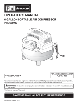
Air Compressor item 15206
PARTS SHOWN FOR REFERENCE ONLY
_ jjjjT,
18 - ENG

Air Compressor item 15206
Item Part No. Description
1 3290408 Flat Washer
2 3220552 Screw, M5x25
3 3410652 Handle
4 3220404 Screw, ST4.2x25
5 3410452 Tooling Cover
6 3630252 Overload, Protector
7 3630150 Power Switch
8 3111352 Electric Wire Assembly
9 3410352 Screw, ST4.2x25
10 3110252 Motor-pump Assembly
11 3110152 Circuit Board
12 3220840 Screw, M4x8
13 3640152 Power Cord
14 3220475 Screw, ST4.8x15
15 3410302- Wire Clip
16 3410552 Cover, Bottom
17 3030150 Tube
I 18 3410329 Zip Tie
19 3420652 Seal Ring
20 3290252 Spring
Qty
1
4
6
4
Qty Item Part No. Description
2 21 3410152 Ball
2 22 3420350 Damping Pad
1 23 3220150 Screw, M6xl 5
4 24 3220250 Screw, M6x25
1 25 3390250 Copper Tube 1
1 26 3290651 Washer 1
1 27 3020152 Copper hoop 2
1 28 3020252 Copper Connector knob 2
1 29 3630152-1 Pressure Controller 1
1 30 3220840 Screw, M4xl0 1/2
1 31 3410350 Fan 1
2 32 3290706 Flat washer 1
1 33 3220205 Screw, M4xl 0 1
1 34 3110752 Pressure Regulator Assembly 1
1 35 3330152-1 Tank, 3G 1
1 36 3290275 Drain Valve Assembly 1
18 37 3420150 Foot 3
1 38 3290750 Flat Washer 6
1 39 3220150 Screw, M6xl 5 3/6
1
19 - ENG

RESOLUCION DE AVERIAS EN EL MARTILLO DE CLAVOS PEQUE_IOS
.w,_v - _ _ Dejedeusarla
herramienta inmediatamente si surge
alguno de los siguientes problemas
durante su funcionamiento. S61o
t6cnicos o centros de servicio
calificados pueden hacer reparaciones
a esta herramienta.
Problem
Air leak near the 1.
top of the tool or
in the trigger area 2.
Air leak near
bottom of tool.
Air leak between 1.
body and 2.
cylinder cap.
Fasteners being 1.
driven too deep. 2.
Tool does not 1.
function well, 2.
does not drive
fasteners, 3.
operates
sluggishly. 4.
Antes de efectuar cualquier reparaci6n
o ajuste, desconecte la herramienta del
suministro de aire. AI reemplazar aros
t6ricos o cilindros, lubriquelos con
aceite para herramientas neumaticas
antes de reensamblarlos.
Possible Causes
O-ring in trigger valve
damaged.
Trigger valve head
damaged.
3. Trigger valve stem, seal,
or O-ring damaged.
1. Loose screws
2. Worn or damaged O-rings
or bumper.
Loose screws.
Worn or damaged O-rings
or seals.
Worn bumper.
Air pressure is too high.
inadequate air supply.
inadequate lubrication.
Worn or damaged O-rings
or seals.
Exhaust port in cylinder
head is blocked.
Probable Solutions
1. Push Power Switch to
On position.
2. Check power at outlet.
3. Plug line cord into electrical
outlet.
1. Tighten screws.
2. Check and replace O-rings
and/or bumper.
1. Tighten screws.
2. Check and replace O-rings
or seals.
1. Replace bumper.
2. Adjust air pressure.
1. Verify adequate air supply.
2. Place 2-6 drops of oil into
air inlet to lubricate.
3. Check and replace O-rings
or seals.
4. Consult qualified service
technician to replace
internal parts.
Tool skips 1. Worn bumper or damaged 1. Replace bumper or loading
fasteners
Tool jams
loading spring.
2. Dirt in front plate.
3. Dirt or damage is
preventing fasteners from
moving, freely in the
magazine.
4. Worn or dried-out O-ring on
piston, or lack of lubrication.
5. Cylinder cover seal leaking.
1. Incorrect or damaged
fasteners.
2. Damaged or worn driver
guide.
3. Magazine or nose screw
loose.
4. Magazine is dirty.
spring.
2. Clean drive channel on
front plate.
3. Clean magazine.
4. O-ring needs to be replacec
or lubricated.
5. Replace sealing washer.
1. Change and use correct
fasteners.
2. Check and replace the
driver guide.
3. Tighten the magazine.
4. Clean the magazine.
36 - SP
/