Page is loading ...

Manuale istruzioni Instruction manual Bedienungsanleitung Manuel d’instructions Manual de instrucciones
R12FXP
R16FXP
R12FX
R16FX
R8FX

November 2011
ITALIANO 3 - 10
ENGLISH 11 - 18
DEUTSCH 19 - 26
FRANÇAIS 27 - 34
ESPAÑOL 35 - 42
APPENDIX 43 - 54
Specifications
Block diagrams
Connectors
Connection examples
Spare parts
The main features of the mixers of this series are the really
compact size, that allows for mounting in a standard 19”
rack, using the optional adapters, the complete
endowment of signal sends and returns and the practical
configuration of the controls, that result in a simple and
immediate utilization.
They are fitted with a dual Montarbo stereo effects
processor, based on a powerful, latest generation, 56 bit
DSP, that provide 2 x 205 high quality programs, with an
uncompromised sound quality (thanks to the dual 24 bit
conversion) mated with unusual ease of use.
The great flexibility of these mixing consoles allows them
to be used both in live applications (thanks to the internal
effect and to the two monitor sends, both with a 3-band
equalizer) and in recording or broadcasting studios
(thanks to the channel’s direct outputs, the four effect
sends, the control-room out and the stereo return). In both
applications, a really useful feature will be the possibility
of plugging-in an analog recorder or of using the practi-
cal USB interface to connect a personal computer, used as
a digital recorder/player, and of monitoring the master
output or the PFL via the headphone output with adjust-
able volume.
The MC-R12FXP and MC-R16FXP powered versions are fit-
ted with a dual channel Class-D power amplifier rated at
750 + 750 W EIAJ. The switch-mode power supply results in
a minimal weight, and the very high efficiency minimizes
the emission of heat, thus increasing the system’s reliability
and prolonging it’s working life.

ITALIANO
4
Mono channels Stereo channels Master section
RIGHT
(
_
20dB)
LEFT
(
_
20dB)
+12
+9
+6
+3
0
-3
-6
-9
-12
-15
-20
-30
+12
+9
+6
+3
0
-3
-6
-9
-12
-15
-20
-30
FX ON
0
3
6
3
6
10
10
20
30
FX 1/AUX 3FX 2/AUX 4
PK
OUTIN
TAPE IN TAPE OUT
CTRL ROOM
PHONES
INS R
INS L
STEREO RET
CTRL ROOM
STEREO RET
R
L
R
L
2
1
R
L
PFL
FX 2 to AUX 1
FX 2 to AUX 2
FX 1 to AUX 1
FX 1 to AUX 2
HIGH
MID
LOW
VOL
PHANTOM
L
LEFT
OUT
RIGHT
OUT
R
MASTER
AUX1 AUX2
FX 1
(AUX3)
FX 2
(AUX4)
FT SW
AUX
2
1
4
3
AUX
FX1/FX2 LOAD
SELECTION
PK
MUTE
USB
TAPE
MIC
13
14
13
14
10
82
4 6
10
8
2
46
MUTE
dB
2K5240
4K5
1K2
800
630
160 Hz
HIGH
R
M
L
+40+12
+50+3
+20 +30
GAIN
MIC
LINE
(
_
10dB)
INS
DIR
OUT
PFL
PK
MID
PAN
LOW
75Hz
1
POST
PRE
AUX 1
AUX 2
FX 1
(AUX 3)
FX 2
(AUX 4)
1
0
3
6
3
6
10
10
20
30
99
33
15 15 dB
99
33
15 15 dB
99
33
15 15 dB
0dB
+6
0dB
+6
0dB
+6
0dB
+6
dB
+35+12
+40+9
+20+30
GAIN
LOW
99
33
15 15 dB
99
33
15 15 dB
99
33
15 15 dB
99
33
15 15 dB
99
33
15 15 dB
99
33
15 15 dB
99
33
15 15 dB
HIGH
99
33
15 15 dB
MID
99
33
15 15 dB
0dB
+6
0dB
+6
0dB
+6
0dB
+6
0dB
+6
0dB
+6
0dB
+6
0dB
+6
0dB
+6
0dB
+6
0dB
+6
0dB
+6
POST
PRE
AUX 1
AUX 2
FX 1
(AUX 3)
FX 2
(AUX 4)
0dB
+6
0dB
+6
0dB
R
O
L
PFL
BAL
0
3
6
3
6
10
10
20
30
SERIES
3
12
NEUTRIK
3
21
NEUTRIK
3
21
NEUTRIK
3
21
NEUTRIK
POWER
I
0
230V 50/60Hz
MB-R16-FX (Internal Fuse): 2,5 A
MB-R16-FXP(Internal Fuse): 9 A
13
14
12
11
1
2
3
4
5
6
7
8
10
9
26
25
24
15
21
22
17
18
19
20
23
40
44
41
39
36
53
42
43
45
50
34
28
30
27
31
32
33
38
37
54
35
47
46
48
49
29
52
51
RL
SPEAKER OUTPUTS
MOD.
MCR16FXP
min Load 4 Ωmin Load 4 Ω
750W + 750W
1 + hot
2 - cold
2 + nc
2 - nc
16
MCR8FX / MCR12FX / MCR16FX / MCR12FXP / MCR16FXP - REAR PANEL
MCR12FXP / MCR16FXP - REAR PANEL
MCR8FX / MCR12FX / MCR16FX / MCR16FXP / MCR12FXP - FRONT PANEL
55
57
56

ENGLISH
11
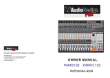
Front and rear panel
......................................................12
Controls and connections
...............................................13 - 15
Dual stereo multieffects DSP
........................................... 16
Audio recording and reproducing via the USB interface
..17
Important !!!
..................................................................18
APPENDIX
Technical specifications
.................................................. 44
Block diagram
................................................................ 45 - 48
Connectors
.....................................................................49
Connections
...................................................................50 - 54
ENGLISH
PACKAGE CONTENTS
Mixing console
MCR8FX / MCR12FX / MCR16FX
OR
Powered mixing console
MCR12FXP/MCR16FXP
Power supply cable
USB cable
CD with recording/playback software
Owner’s manual
Warranty certificate
CE declaration of conformity
IMPORTANT ! Safety insructions
WARNING !
In order to protect your own and others’ safety and to avoid
invalidation of the warranty of this product, please read this
section carefully before operating this product.
- This product has been designed and manufactured for being operated as
mixing console/powered mixing console in the applications tipical of a sound
reinforcement system or of a sound recording system. Operation for purposes and
in applications other than these has not been covered by the manufacturer in the
design of the product, and is therefore to be undertaken at end user’s and/or
installer’s sole risk and responsability.
- This unit conforms to Class I insulation, and for safe use it is required that
the protective earth contact is connected to a grounded (earthed) outlet.
TO AVOID THE RISK OF FIRE AND/OR ELECTRIC SHOCK:
• Never expose this product to rain or moisture, never use it in proximity of water
or on a wet surface. Never let any liquid, as well as any object, enter the product.
In case, immediately disconnect it from the mains supply and refer to servicing
before operating it again. Never place burning candles or other sources of open
flame on top of the device.
• Before connecting this product to the mains supply, always make sure that
the voltage on the mains outlet corresponds to that stated on the product.
• This product must be connected only to a grounded mains outlet complying
to the safety regulations in force via the supplied power cable.
In case the power cable needs to be substituted, use exclusively a cable of the
same type and characteristics.
• This device is connected to the power line even when the mains switch is in
the 0 (off) position and the power indicator is off. As long as it is plugged in
there are dangerous electrical potentials inside the device, so, before undertaking
any sort of maintenance work etc., always make sure it has been unplugged
from the mains socket.
• Never place any object on the power cable. Never lay the power cable on a
walkway where one could trip over it. Never press or pinch it.
• MCR12FXP/MCR16FXP: always provide adequate airflow for cooling.
Never obstruct the air intake openings.
• Leave enough room to get to the mains power socket and the mains connector
on the back panel.
• Always make sure the On/Off switch is in its Off position (0) before doing any
operation on the connections.
• Before attempting to move the product after it has been installed, remove
all the connections.
• To disconnect the power cable from the mains supply never pull the cable
directly: instead, hold the body of the plug firmly and pull it gently from the
mains supply outlet.
CAUTION !
This product does not contain user serviceable parts.
To prevent fire and/or electrical shock, never disassemble it
and never remove its cover. For maintenance and servicing always
refer to the official Montarbo Distributor in your Country or
to qualified personnel specifically authorised by the Distributor.
- Before placing the product on a surface of any kind, always make sure that its
shape and load rating will safely match the product’s size and weight.
- To avoid shocks, kicks, or whatever action, always reserve a protected area
with no access to unqualified personnel as installation site of the product.
In case the product is used near children and animals closest supervision is
necessary.
- This product in combination with headphones or speakers can generate very
high acoustic pressures which are dangerous for the hearing system.
Do not operate for a long period of time at a high or unconfortable volume level.
☛ Never expose children to high sound sources.
The lighting flash with arrowhead symbol within an equilateral triangle, is intended to alert
the user to the presence of uninsulated "dangerous voltage" within the product's enclosure,
that may be of sufficient magnitude to constitute a risk of electric shock to humans.
The exclamation point within an equilateral triangle, is intended to alert the user to the
presence of important operating and maintenance (servicing) instructions.

ENGLISH
12
Mono channels Stereo channels Master section
RIGHT
(
_
20dB)
LEFT
(
_
20dB)
+12
+9
+6
+3
0
-3
-6
-9
-12
-15
-20
-30
+12
+9
+6
+3
0
-3
-6
-9
-12
-15
-20
-30
FX ON
0
3
6
3
6
10
10
20
30
FX 1/AUX 3FX 2/AUX 4
PK
OUTIN
TAPE IN TAPE OUT
CTRL ROOM
PHONES
INS R
INS L
STEREO RET
CTRL ROOM
STEREO RET
R
L
R
L
2
1
R
L
PFL
FX 2 to AUX 1
FX 2 to AUX 2
FX 1 to AUX 1
FX 1 to AUX 2
HIGH
MID
LOW
VOL
PHANTOM
L
LEFT
OUT
RIGHT
OUT
R
MASTER
AUX1 AUX2
FX 1
(AUX3)
FX 2
(AUX4)
FT SW
AUX
2
1
4
3
AUX
FX1/FX2 LOAD
SELECTION
PK
MUTE
USB
TAPE
MIC
13
14
13
14
10
82
4 6
10
8
2
46
MUTE
dB
2K5240
4K5
1K2
800
630
160 Hz
HIGH
R
M
L
+40+12
+50+3
+20 +30
GAIN
MIC
LINE
(
_
10dB)
INS
DIR
OUT
PFL
PK
MID
PAN
LOW
75Hz
1
POST
PRE
AUX 1
AUX 2
FX 1
(AUX 3)
FX 2
(AUX 4)
1
0
3
6
3
6
10
10
20
30
99
33
15 15 dB
99
33
15 15 dB
99
33
15 15 dB
0dB
+6
0dB
+6
0dB
+6
0dB
+6
dB
+35+12
+40+9
+20+30
GAIN
LOW
99
33
15 15 dB
99
33
15 15 dB
99
33
15 15 dB
99
33
15 15 dB
99
33
15 15 dB
99
33
15 15 dB
99
33
15 15 dB
HIGH
99
33
15 15 dB
MID
99
33
15 15 dB
0dB
+6
0dB
+6
0dB
+6
0dB
+6
0dB
+6
0dB
+6
0dB
+6
0dB
+6
0dB
+6
0dB
+6
0dB
+6
0dB
+6
POST
PRE
AUX 1
AUX 2
FX 1
(AUX 3)
FX 2
(AUX 4)
0dB
+6
0dB
+6
0dB
R
O
L
PFL
BAL
0
3
6
3
6
10
10
20
30
SERIES
3
12
NEUTRIK
3
21
NEUTRIK
3
21
NEUTRIK
3
21
NEUTRIK
POWER
I
0
230V 50/60Hz
MB-R16-FX (Internal Fuse): 2,5 A
MB-R16-FXP(Internal Fuse): 9 A
13
14
12
11
1
2
3
4
5
6
7
8
10
9
26
25
24
15
21
22
17
18
19
20
23
40
44
41
39
36
53
42
43
45
50
34
28
30
27
31
32
33
38
37
54
35
47
46
48
49
29
52
51
RL
SPEAKER OUTPUTS
MOD.
MCR16FXP
min Load 4 Ωmin Load 4 Ω
750W + 750W
1 + hot
2 - cold
2 + nc
2 - nc
16
MCR8FX / MCR12FX / MCR16FX / MCR12FXP / MCR16FXP - REAR PANEL
MCR12FXP / MCR16FXP - REAR PANEL
MCR8FX / MCR12FX / MCR16FX / MCR16FXP / MCR12FXP - FRONT PANEL
55
57
56

ENGLISH
13
Controls and connections
MONO INPUT CHANNEL
1 ➤ GAIN: adjust the gain (sensitivity) of the input stage, allowing
connections of signal sources (both line and mic level) having a wide
range of signal level. As a practical rule, the GAIN control must be set
to the maximum allowable level that will not activate the peak level
indicator (PK). This will maximize the signal to noise ratio.
2 ➤ Pushbutton that enables the 75 Hz, 12 dB/oct, high-pass filter.
This filter decreases the low-frequency gain in those input channels
where there is no real low frequency content (e.g.: those used for voice
and for many instruments) and will result in a cleaner sound, reducing
the feedback from stage monitors and increasing the available dynamics.
3 ➤ HIGH / MID / LOW: 3-band Equalizer with parametric control of the
mid range. The High and Low controls act on fixed frequency bands,
the Mid control allows to choose the frequency to be boosted or cut.
HIGH: adjusts the amount of boost or cut in the high frequency range
(±15dB@10kHz). Turning the control clockwise increases the gain at
high frequencies, counter-clockwise decreases it. The response is flat
at the center position.
MID kHz: chooses the center frequency of the mid-range band to be
boosted or cut (160 Hz ÷4.5 kHz).
MID dB: adjusts the amount of boost or cut (±15dB) at the frequency
set by the MID kHz control.
Note: If the MID dB control is set at ‘0’ (centre) there will be no alteration
in the mid frequency band (independently of the MID kHz control setting).
LOW: adjusts the amount of boost or cut in the low frequency range
(±15dB@80Hz). Turning the control clockwise increases the amount of
low frequencies, counter-clockwise decreases it. The response is flat at
the center position.
4 ➤ AUX1 / AUX 2: auxiliary sends volumes. They set the level of that
input channel in the AUX1 and AUX2 outputs.
The PRE / POST pushbutton routes these control before (PRE) or after
(POST) the channel’s volume fader. The first setting (PRE) is usually used
for monitor sends, the other (POST) for external effect sends.
In both settings the signal is POST-EQ (that means the signal is always
affected by the channel’s equalizers settings).
5 ➤ FX1 (AUX3) / FX2 (AUX4): volumes of auxiliary sends no. 3 and 4.
These adjust the signal sent to the two internal stereo effects units
(FX1 and FX2) but, if the effects units are disabled, the signal is sent
to the AUX3 and AUX4 auxiliary outputs, to drive external effects or
additional monitors. The signal is always post-fade and post-eq (it is
affected by equalizer’s and fader’s settings).
6 ➤ PAN: this control allows to place the channel’s input signal within
the stereo image by assigning more or less of the channel’s signal to
the left and right master outputs.
7 ➤ PFL: this pushbutton enables the channel’s pre-fade listening.
If the button is pressed, the channel’s signal is sent to the headphones
amplifier (42) and the channel’s level is shown by the master level
indicators (52), even if the channel is muted (MUTE pushbutton - 8 -
pressed) or the volume fader (9) is at it’s minimum setting.
Listening and checking via the PFL allows to finely adjust the channel’s
equalizer and gain settings without routing the channel to the master
outputs. The LED is on when PFL is enabled. It is possible to enable the
PFL on more than one channel at the same time.
8 ➤ MUTE: channel’s main on/off switch with LED indicator.
When pushed, the channel’s signal is not sent to the L/R master
outputs, AUX1 and AUX2, FX1 and FX2 outputs. We suggest to mute
every unused channel, to reduce the noise in the outputs.
9 ➤ PK: peak LED indicator. It lights when the signal level is
approaching the maximum (clipping) allowable level.
The signal is sampled in two points of the channel’s signal path:
after the input amplifier (micro and line) and after the equalizer.
It is unaffected by channel’s fader setting. If the LED is continuously
lighted, you must reduce the input GAIN (1) settingor modify the
equalizer settings, reducing the boost introduced by the tone controls.
This indicator is not affected by the setting of the channels volume
fader.
10 ➤ Channel VOLUME fader. It adjusts the channel’s volume in the L/R
master outputs and in all the auxiliary POST fade outputs.
● connections:
11 ➤ MIC: balanced XLR microphone input (for microphones).
It is fitted with 48V dc ‘phantom’ power for condenser microphones,
that is enabled by the PHANTOM switch (50) located in the master
section. Use this input only for balanced sources. Do not connect it to
unbalanced sources.
12 ➤ LINE: balanced jack line input (stereo jack), for instruments and
high level sources. It may be connected to both balanced (stereo jack
plug) and unbalanced (mono jack plug) sources.
13 ➤ INS (INSERT): stereo jack for channel’s insert in/out. When a stereo
jack is plugged in, the channel’s signal path is opened, and it is possible
to connect an external unit (an effect or an equalizer) in series with the
channel’s signal path. The signal is affected by channel’s GAIN setting,
but unaffected by chalnnel’s equalizer and fader settings.
14 ➤ DIR OUT: channel’s direct output (unbalanced jack), suitable to
send the channel’s signal to an external unit (typically a multi-track
recorder). The signal is post-eq and post-fader, that means it is affected
by the settings of channel’s equalizer and volume.
It is possible, with a simple modification performed by an authorized
service center, to switch this output pre-fade (making it independent
from channel’s volume).
Note: Do not connect instruments or other high level sources to the
MICRO inputs (this will result in distortion due to excessive signal level).
Do not connect microphones to the LINE inputs (the resulting signal will
be of low level and low quality).

ENGLISH
14
Controls and connections
STEREO INPUT CHANNEL
15 ➤ GAIN: same as in the mono channel.
16 ➤ HIGH / MID / LOW: 3-band Equalizer.
HIGH: adjusts the amount of boost or cut in the high frequency
range (±15dB@10kHz). Turning the control clockwise increases the
amount of high frequencies, counter-clockwise decreases it.
The response is flat at the center position.
MID: adjusts the amount of boost or cut (±15dB) of the mid frequency
band. The band’s center frequency is set at 2.5 kHz. Turning the control
clockwise increases the amount of mid frequencies, counter-clockwise
decreases it. The response is flat at the center position.
LOW: adjusts the amount of boost or cut in the low frequency
range (±15dB@80Hz). Turning the control clockwise increases the
amount of low frequencies, counter-clockwise decreases it.
The response is flat at the center position.
17 ➤ AUX1 / AUX 2: same as in the mono channel..
18 ➤ FX1 (AUX3) / FX2 (AUX4): same as in the mono channel.
19 ➤ BAL: balance control: this control adjust the relative levels of the
channels’ left and right signals in the master L/R outputs.
If the channels is used as a mono channel this controls doubles as a
PAN (panorama) control.
20 ➤ PFL: same as in the mono channel.
21 ➤ MUTE: same as in the mono channel.
22 ➤ PK: same as in the mono channel.
23 ➤ Channel VOLUME fader: same as in the mono channel.
● connections:
24 ➤ MIC: balanced XLR input for mic-level signals.
When using this input the channel becomes a mono input channel.
25 ➤ RIGHT: balanced (stereo jack) line input for instruments and
other high-level sources. It may be connected to both balanced (stereo
jack plug) and unbalanced (mono jack plug) sources.
26 ➤ LEFT: balanced (stereo jack) line input for instruments and other
high-level sources. It may be connected to both balanced (stereo jack
plug) and unbalanced (mono jack plug) sources.
DUAL STEREO MULTIEFFECTS DSP
The two stereo effects processors are based on a 56-bit DSP with 24-bit
Delta-Sigma conversion. Both provide 205 programs of high perfor-
mance digital audio processing combined with extremely easy operation.
27 ➤ 2-Line (E1 and E2) Liquid Crystal Display.
Shows the numbers and the names of the currently selected program.
28 ➤ FX1/FX2 BUTTON. It allows to select to operate on one of the
two effects group (E1 or E2 lines on the LCD).
29 ➤ SELECTION. Program selection knob: allows selecting one of
the 205 programs available for each of the two effects (FX1 and FX2).
30 ➤ LOAD button: allows loading and activating the program
selected with the SELECTION knob.
= shows that the selected program has been loaded.
= shows that the selected program has not yet been loaded.
31 ➤ FX1/AUX3 and FX2/AUX4: these pushbutton enable/disable the
corresponding internal effect unit. When the effects is enabled, the FX
ON LED is lighted. When the effect is disabled, corresponding FX mix is
sent to the AUX3 or AUX4 outputs (36), allowing to drive external
effects units or monitors. The PK LEDs are lighted when the signal
level of the FX1 and FX2 mix is too high and there is a risk of saturation
of the internal effect. The FX1 and FX2 sends are correctly adjusted
when these LEDs flash only occasionally on signal peaks. If a LED is
continuously lighted it indicates signal overload and it is necessary to
reduce the effect send volumes (FX1 or FX2) on individual channels.
32 ➤ FX1 to AUX1 and FX2 to AUX1 monitor sends: they adjust the
level of the internal effects FX1 and FX2 (when enabled) on AUX1 output.
33 ➤ FX1 to AUX2 and FX2 to AUX2 monitor sends: as above, they
adjust the level of the internal effects FX1 and FX2 (when enabled)
on AUX 2 output.
34 ➤ FX1 (AUX3) and FX 2 (AUX4): volume control of the internal
effects FX1 and FX2 (when enabled) on the master L/R outputs.
When the internal effects are disabled, these pots adjust the output
level of the AUX3 and AUX4 external sends.
● connections:
35 ➤ FT SW 1/2: jack sockets for connection of remote footswitches.
They allow to enable/disable the internal effects processor with a
remote foot-switch. They operate only if the internal effects are enabled
by the corresponding button (31).
36 ➤ AUX 3/4: unbalanced jack sockets of the AUX3 and AUX4 outputs.
If the internal effects are disabled, the corresponding AUX mixes are
sent to these outputs and the levels are adjusted by the AUX3 and
AUX4 volume controls (34). Each output can drive up to 10 parallel
connected active speaker enclosures or power amplifiers.

ENGLISH
15
Controls and connections
EXTERNAL EFFECTS SENDS/RETURNS
37 ➤ AUX1 and AUX2: volume controls of the AUX1 and AUX2
(monitor) outputs.
38 ➤ HIGH / MID / LOW. Three-band equalizer on the AUX
(monitor) outputs.
HIGH: ±15dB@10kHz - MID: ±[email protected] kHz - LOW: ±15dB@80Hz
39 ➤ AUX 1/2: unbalanced jack sockets of the AUX1 and AUX2
outputs. The output levels are adjusted by the corresponding volume
controls (37). Each output can drive up to 10 parallel connected active
speaker enclosures or power amplifiers.
40 ➤ STEREO RET L/R: unbalanced jack sockets for the external stereo
effects return.
41 ➤ STEREO RET: this potentiometer adjusts the volume of the external
stereo effects return (40) on the master L/R outputs.
ACCESSORIES
42 ➤ PHONES: jack socket for the stereo headphones.
The phones signal is the main stereo (L/R) or the pre-fade mix of all
those input channels where a PFL pushbutton is depressed.
43 ➤ PHONES: volume control of the stereo headphones output (42).
44 ➤ CTRL ROOM L/R: jack socket for the stereo CONTROL ROOM.
The signal is the same of the master L/R outputs, but the level is
indipendent from L/R master volume settings. This output is really useful
in many applications: in clubs, restaurants or theaters it may drive a
second group of active loudspeakers, with a level control that is
independent from that of the main system, thus creating a two-zone
audio system with independent volume adjustment, or to drive active
monitor loudspeakers to have a direct control of main output signal.
In studio applications, these outputs are used to drive the main monitor
speakers. The level of these outputs is adjusted by the CTR ROOM
control (45) and is independent from L/R master levels.
Each output can drive up to 10 parallel connected active speaker
enclosures or power amplifiers.
45 ➤ CTRL ROOM: volume control of the corresponding output (44)
46 ➤ TAPE IN/OUT L/R: PIN sockets for the input/output analog interface
of a stereo tape recorder. These sockets are active if the USB/TAPE
pushbutton (48) is set to TAPE.
Please note: TAPE IN L and R inputs are standard, line-level inputs and
thus they may be used to connect any line-level source (mixer outputs,
instruments, expanders, etc.).
47 ➤ USB: digital USB interface to connect a PC to be used as
recorder/reproducer.
This interface is active if the USB/TAPE pushbutton (48) is set to USB.
48 ➤ USB/TAPE: pushbutton that selects the interface to be used
for recording/reproduction
49 ➤ IN / OUT: input (IN) and output (OUT) volume control for the
active recording/reproduction interface.
Please note: for more detailed informations about the connection
of a Personal Computer as a recording/reproduction device, please
refer to fig. 5A and 5B at page 54.
50 ➤ PHANTOM: main switch of the ’phantom’ power supply on
microphone inputs, with LED indicator.
MASTER L/R OUTPUTS
51 ➤ MASTER L/R: volume controls (faders) of the L (left) and R (right)
master outputs.
52 ➤ 12-segment LED indicators of master L/R output levels.
If an input channel’s PFL button is pressed, the PFL level is displayed
instead of L/R master level, and the PFL LED is on.
53 ➤ LEFT OUT and RIGHT OUT: balanced XLR3 male sockets of
the L/R master outputs.
Each output can drive up to 10 parallel connected active speaker
enclosures or power amplifiers.
54 ➤ INS L and INS R: stereo jack INSERT sockets on L/R master outputs.
Please note: the INSERT jack sockets may be used as unbalanced
outputs, using a standard mono jack plug. In this case the XLR outputs
will be disconnected. This way you can use jack or XLR sockets,
according to the connectors fitted to the available amplifiers or active
speakers or to the connection cables.
REAR PANEL
55 ➤ IEC60320 mains input socket with fuse socket.
Use with the supplied mains cord only.
56 ➤ Mains ON/OFF switch.
MCR16FXP and MCR12FXP POWERED MODELS
57 ➤ Output connectors for the internal power amplifiers. Each chan-
nel is fitted with a 4 pole Speakon
®
and a mono jack, wired in parallel.

New algorithms, running on powerful, latest generation's DSP, emulate
the acoustic characters of various ambient, an a new series of programs
is available to enhance the acoustic character of various instruments.
Programs and effects description
1 ➔ 5 EARLY
Generates the initial part of room reverberation, without the decay of
the reverberant field.
6 ➔ 14 STEREO GEN
Generates a pseudo-stereo effect out of mono sources by adding short
delays to the signal.
15 ➔ 18 PING PONG
A delayed sound is bounced between the stereo channels. The delay
time increases with the preset number.
19 ➔ 23 HALO
A digital recreation of the tried and proven Montarbo magnetic memo-
ry effect. Suggested for Vintage or Psyco voices.
24 ➔ 36 DELAY
A simple delay, with the delay time increasing with the preset number.
It will add a pleasant openness to any sound.
37 ➔ 40 DETUNE
Slightly changes the tuning of the source. It enriches the sound without
rendering it "unnatural". Test it on sustained vocals.
41 ➔ 45 FLANGER
A powerful effect that gives a strong character to the sound.
Both Stereo and Mono presets will perform best with long sustained
instruments.
46 ➔ 54 CHORUS
A choir effect is simulated by modulating both delay and amplitude.
Stereo presets result in a "wider" stage.
55 ➔ 57 AMBIENCE
It emulates a small room, with reflecting surfaces. Early reflections
predominate, with a slight reverberation.
58 ➔ 61 CHAMBER
A room slightly larger than the former, with more sound adsorbing
surfaces.
62 ➔ 66 ROOM
The size is that of a living room. The presets alternate between reflec-
ting and adsorbing surfaces.
67 ➔ 73 HALL
A large, empty room, with mostly reflecting, naked walls: the typical
party hall.
74 ➔ 75 CATHEDRAL
A very large room, such a church or a cathedral.
76 ➔ 78 PLATE
It recreates the sound of the first electro-mechanical reverberation devi-
ces, that used metal plates for a large and brilliant sound.
79 ➔ 81 PLATE DLY
A slight echo is added to the Plate effect, giving an even larger sound.
82 ➔ 85 BIG SPACE
A really spacious room. The sound is unnatural but really evocative.
86 ➔ 88 ECO REV
One of the most commonly used effects: it blends the depth of the
echo with the warmth of the reverb. Usually applied to vocals, it is the
classical starting point for testing effects.
89 ➔ 92 CONCERT
The acoustic space of a large concert hall with controlled reflections
and a neutral tonal character.
93 ➔ 95 LIVE
It will give you the sensation of a live concert in an open space, on a
large stage in front of thousands of listeners.
96 ➔ 99 GATE
The reverberation decay is suddenly muted, giving the sound an aggres-
sive character.
100 ➔ 134 VOX - FLUTE - TRUMPET - SAX - BRASS -
KEYBRD - PIANO - GTR - DRUM - TOMS - CYMB - HIHAT -
KICK - SNARE - TOM
This preset group includes custom-made effects for specific instruments,
readily available without time-consuming programming.
135 INSIDE A BOX
Similar to Room (63-66), but the room's size is very small.
136 LIVING ROOM
Similar to the former, but the room's size is larger (a typical living room).
137 ➔ 144 PTC REV
A pleasant reverberation is added to the pitch transposed signal descri-
bed below.
145 ➔ 155 PITCH
These presets generate signals that are harmonic with the source, but
transposed in terms of pitch.
156 ➔ 165 DISTANCE
It is a simple delay of the input signal, useful in installations with many
loudspeakers at different distances from the listeners. With the AUX
outputs it is possible to drive other active speakers placed nearer the
listeners than the main speakers. The delay time increases with the
preset number at 5 meter increments.
166 ➔ 175 *ECHO
Classic multiplex effect. Delay time increases with program
number.
176 ➔ 185 ECHO + REVERB
Delay and reverb blended together make for the impressive effect you
can listen on most contemporary productions.
186 ➔ 195 *VOICE REVERB
Reverbs specially tailored to enhance vocals’ character.
196 ➔ 205 *HALO + REVERB
Halo and reverb effects blended together.
Dual stereo multieffects processor
ENGLISH
16

ENGLISH
17
Audio recording and reproducing via the USB interface
USB CONNECTION PRECAUTIONS
Be sure to observe the following points when connecting to the
computer’s USB interface (47).
Failure to observe these rules can result in computer freezes/hang-ups
and possibly data loss or corruption.
If the MCR series mixer or computer does hang up, turn the power
to both devices off and then on again, and restart the computer.
• Be sure to wake the computer from sleep/suspended/standby mode
before making a connection to the computer’s USB connector.
• Connect the ixer to the computer before turning the mixer power on.
• Always quit all applications running on the computer before turning
the MCR series mixer’s power on or off, or connecting or disconnecting
the USB cable.
• Wait at least 6 seconds between turning the MCR series mixer on or
off, and between connecting or disconnecting the USB cable.
When connecting or disconnecting the USB cable be sure to turn the
USB/TAPE input volume control (49) to it’s minimum.
Disconnect the USB cable when using the MCR series mixer without the
computer.
Windows
®
Version RAM Processor speed
2000, XP 512 MB 1 GHz
Vista Home Basic 2 GB 1 GHz
Vista Home Premium, Business, Ultimate 4 GB 2 GHz
Windows 7: Same of Windows Same of Windows
preliminary support (’Beta’ version) Vista Vista
Mac
®
OS Version RAM Processor speed
10.4 or later 64 MB 300 MHz
The Compact Disc supplied with the mixer contains a copy of the
Audacity
®
software program. Audacity
®
is free, open source software
for recording and editing sounds. It is available for Mac OS X, Microsoft
Windows, GNU/Linux, and other operating systems.
You can use Audacity to:
• Record live audio.
• Convert tapes and records into digital recordings or CDs.
• Edit Ogg Vorbis, MP3, WAV or AIFF sound les.
• Cut, copy, splice or mix sounds together.
• Change the speed or pitch of a recording.
• And more!
Audacity is free software, developed by a group of volunteers and
distributed under the GNU General Public License (GPL).
For any further information an for downloading the latest version
please visit the Audacity homepage at: http://audacity.sourceforge.net/
The files contained in the CD are the following:
1) audacity-win-unicode-1.3.12.exe for Windows
®
2000, XP, Vista, 7.
2) audacity-macosx-ub-1.3.12.dmg for Mac
®
OS X.
The installation software for other operating systems (previous versions
of Windows® and Mac® ) and the source code for compiling a Linux
version may be downloaded from:
http://audacity.sourceforge.net/download/
System requirements: CD/DVD reader (for installation)
• Install the software by launching the installation le corresponding
to your operating system. Follow the instructions that are displayed
during the installation process.
• Connect the computer to the mixer via an USB cable.
The mixer’s USB audio interface will be automatically recognized by
the operating system, and will be reported as ‘USB audio codec’ or
‘USB speakers’.
• Launch Audacity and select, as default audio in/out interface, the
mixer’s USB audio interface (not the computer’s internal audio card).
To do this, select from Audacity’s menu the function:
Edit > Preferences> Devices and set:
Playback: USB audio codec
Recording: USB audio codec / Channels : 2 (stereo).
• The use of the software program is intuitive, and it includes an
exhaustive help system, always up-to-date.

Important !!!
CARE AND MAINTENANCE
• This device has been designed for operation in tropical and very hot
climates.
• Never place burning candles or other sources of open ames on top
of the mixer.
• Never expose the mixer to heat sources such as radiators or other
products that produce heat.
• Never expose the mixer to direct sunlight, excessive vibrations or
mechanical shocks.
• Avoid operating and storing the mixer in damp or dusty places:
this will avoid malfunctions and premature degrading of specifications.
• When setting up the system outdoors, make sure to protect it
against rain.
• Avoid using the mixer close to strong sources of electromagnetic
interferences (e.g. video monitors, high power electrical cabling).
This may lead to degradation of audio quality.
• Care should be taken so that objects do not fall and liquids are not
spilled into the mixer. In public events take special care in selecting the
mixer location, and don’t let people, musicians, technicians or anyone
put glasses, cups, food or drinks containers, ashtrays and lighted
cigarettes on the mixer.
• Take care of the connectors cables, always coil them avoiding knots
and twists.
• Never apply excessive force to the controls (knobs, sliders, pushbuttons).
• Use a soft brush or a jet of air to clean the panel. Do not use alcohol,
solvents or detergents
• Before making any connection to the mixer, make sure that the mains
switch is in the “O” (off) position.
• As long as it is plugged in, dangerous electrical potentials may be
present inside the device, so, before undertaking any sort of mainte-
nance work etc., always make sure it has been unplugged from the
mains socket.
• If service is needed, refer to qualied service personnel only or to the
Montarbo distributor in your country.
CONNECTION TO MAINS SUPPLY
• Make sure that the mains switch is in it’s ‘0’ (off) position.
• Check that mains voltage corresponds to the voltage indicated on
the panel.
• Use only the factory supplied mains cable or, if a different plug style
plug is needed, a suitable cable with a ground connection and marked
with the safety approvals valid in the country of use.
Always connect it to a grounded outlet.
• Leave enough room to get to the mains power socket and the mains
connector on the back panel. As long as it is plugged in, dangerous
electrical potentials may be present inside the device, even when the
mains switch is in the ‘0’ (off) position and the power indicator is off,
so, before undertaking any sort of maintenance work etc., always
make sure it has been unplugged from the mains socket.
INSTALLATION AND FIRST OPERATION
• Always use quality cables and connectors.
• Use shielded cables for your connections to the micro and line
inputs, to the send/return sockets, to the effect send and monitor
outputs, to the tape in/out and to the Control Room outputs.
• For model MCR12FX/MCR16FX mixers. Use shielded cables for
connection of active speakers to the master L and R outputs.
• For model MCR12FXP/MCR16FXP powered mixers.
Use unshielded cables with adequate copper section (2.5 mm
2
min.)
for connection of passive speakers to the master L and R outputs.
Never use the internal amplifiers with loads lower than 4 ohm each
channel.
• Before switching on or off the mixer turn off or disconnect the
speaker enclosures connected to the mixing console. This will avoid
switching noises that may cause damages to loudspeakers.
PRELIMINARY CONNECTIONS AND SETTINGS
• Connect the speaker enclosures
• Connect the microphones to the XLR sockets, the line level sources
and the instruments to the jack sockets.
Do not connect microphones to LINE inputs.
• Before turning on the mixer, set the channel volume faders and the
master volume faders to their lowest settings.
• Switch on the unit and turn the gain controls to their lowest settings,
the tone controls and pan pots to the middle position, and the auxiliary
and effect sends anti-clockwise to their lowest settings.
• To optimize dynamics of each channel according to the various signal
sources, proceed as follows:
- using a microphone (connected to the XLR mic input) in conditions
typical of the intended use, set the GAIN control so as to cause the PK
LED to illuminate;
- now reduce the GAIN just enough until the PK LED switches off and
adjust the volume.
• The channel’s peak LED is affected only by the GAIN control and the
TONE controls.
Note: Repeat the above procedure for all the channels, one at a time,
using the signal source assigned to that channel and simulating real
operating conditions as closely as possible.
• Set the volume faders of the L/R master outputs and of the internal
effects near to the ‘0’ setting and the faders of the monitor volume
controls to the middle position, now adjust the volume and the monitor
sends of each channel according to your requirements.
ENGLISH
18

DEUTSCH
20
Mono channels Stereo channels Master section
RIGHT
(
_
20dB)
LEFT
(
_
20dB)
+12
+9
+6
+3
0
-3
-6
-9
-12
-15
-20
-30
+12
+9
+6
+3
0
-3
-6
-9
-12
-15
-20
-30
FX ON
0
3
6
3
6
10
10
20
30
FX 1/AUX 3FX 2/AUX 4
PK
OUTIN
TAPE IN TAPE OUT
CTRL ROOM
PHONES
INS R
INS L
STEREO RET
CTRL ROOM
STEREO RET
R
L
R
L
2
1
R
L
PFL
FX 2 to AUX 1
FX 2 to AUX 2
FX 1 to AUX 1
FX 1 to AUX 2
HIGH
MID
LOW
VOL
PHANTOM
L
LEFT
OUT
RIGHT
OUT
R
MASTER
AUX1 AUX2
FX 1
(AUX3)
FX 2
(AUX4)
FT SW
AUX
2
1
4
3
AUX
FX1/FX2 LOAD
SELECTION
PK
MUTE
USB
TAPE
MIC
13
14
13
14
10
82
4 6
10
8
2
46
MUTE
dB
2K5240
4K5
1K2
800
630
160 Hz
HIGH
R
M
L
+40+12
+50+3
+20 +30
GAIN
MIC
LINE
(
_
10dB)
INS
DIR
OUT
PFL
PK
MID
PAN
LOW
75Hz
1
POST
PRE
AUX 1
AUX 2
FX 1
(AUX 3)
FX 2
(AUX 4)
1
0
3
6
3
6
10
10
20
30
99
33
15 15 dB
99
33
15 15 dB
99
33
15 15 dB
0dB
+6
0dB
+6
0dB
+6
0dB
+6
dB
+35+12
+40+9
+20+30
GAIN
LOW
99
33
15 15 dB
99
33
15 15 dB
99
33
15 15 dB
99
33
15 15 dB
99
33
15 15 dB
99
33
15 15 dB
99
33
15 15 dB
HIGH
99
33
15 15 dB
MID
99
33
15 15 dB
0dB
+6
0dB
+6
0dB
+6
0dB
+6
0dB
+6
0dB
+6
0dB
+6
0dB
+6
0dB
+6
0dB
+6
0dB
+6
0dB
+6
POST
PRE
AUX 1
AUX 2
FX 1
(AUX 3)
FX 2
(AUX 4)
0dB
+6
0dB
+6
0dB
R
O
L
PFL
BAL
0
3
6
3
6
10
10
20
30
SERIES
3
12
NEUTRIK
3
21
NEUTRIK
3
21
NEUTRIK
3
21
NEUTRIK
POWER
I
0
230V 50/60Hz
MB-R16-FX (Internal Fuse): 2,5 A
MB-R16-FXP(Internal Fuse): 9 A
13
14
12
11
1
2
3
4
5
6
7
8
10
9
26
25
24
15
21
22
17
18
19
20
23
40
44
41
39
36
53
42
43
45
50
34
28
30
27
31
32
33
38
37
54
35
47
46
48
49
29
52
51
RL
SPEAKER OUTPUTS
MOD.
MCR16FXP
min Load 4 Ωmin Load 4 Ω
750W + 750W
1 + hot
2 - cold
2 + nc
2 - nc
16
MCR8FX / MCR12FX / MCR16FX / MCR12FXP / MCR16FXP - REAR PANEL
MCR12FXP / MCR16FXP - REAR PANEL
MCR8FX / MCR12FX / MCR16FX / MCR16FXP / MCR12FXP - FRONT PANEL
55
57
56

FRANÇAIS
28
Mono channels Stereo channels Master section
RIGHT
(
_
20dB)
LEFT
(
_
20dB)
+12
+9
+6
+3
0
-3
-6
-9
-12
-15
-20
-30
+12
+9
+6
+3
0
-3
-6
-9
-12
-15
-20
-30
FX ON
0
3
6
3
6
10
10
20
30
FX 1/AUX 3FX 2/AUX 4
PK
OUTIN
TAPE IN TAPE OUT
CTRL ROOM
PHONES
INS R
INS L
STEREO RET
CTRL ROOM
STEREO RET
R
L
R
L
2
1
R
L
PFL
FX 2 to AUX 1
FX 2 to AUX 2
FX 1 to AUX 1
FX 1 to AUX 2
HIGH
MID
LOW
VOL
PHANTOM
L
LEFT
OUT
RIGHT
OUT
R
MASTER
AUX1 AUX2
FX 1
(AUX3)
FX 2
(AUX4)
FT SW
AUX
2
1
4
3
AUX
FX1/FX2 LOAD
SELECTION
PK
MUTE
USB
TAPE
MIC
13
14
13
14
10
82
4 6
10
8
2
46
MUTE
dB
2K5240
4K5
1K2
800
630
160 Hz
HIGH
R
M
L
+40+12
+50+3
+20 +30
GAIN
MIC
LINE
(
_
10dB)
INS
DIR
OUT
PFL
PK
MID
PAN
LOW
75Hz
1
POST
PRE
AUX 1
AUX 2
FX 1
(AUX 3)
FX 2
(AUX 4)
1
0
3
6
3
6
10
10
20
30
99
33
15 15 dB
99
33
15 15 dB
99
33
15 15 dB
0dB
+6
0dB
+6
0dB
+6
0dB
+6
dB
+35+12
+40+9
+20+30
GAIN
LOW
99
33
15 15 dB
99
33
15 15 dB
99
33
15 15 dB
99
33
15 15 dB
99
33
15 15 dB
99
33
15 15 dB
99
33
15 15 dB
HIGH
99
33
15 15 dB
MID
99
33
15 15 dB
0dB
+6
0dB
+6
0dB
+6
0dB
+6
0dB
+6
0dB
+6
0dB
+6
0dB
+6
0dB
+6
0dB
+6
0dB
+6
0dB
+6
POST
PRE
AUX 1
AUX 2
FX 1
(AUX 3)
FX 2
(AUX 4)
0dB
+6
0dB
+6
0dB
R
O
L
PFL
BAL
0
3
6
3
6
10
10
20
30
SERIES
3
12
NEUTRIK
3
21
NEUTRIK
3
21
NEUTRIK
3
21
NEUTRIK
POWER
I
0
230V 50/60Hz
MB-R16-FX (Internal Fuse): 2,5 A
MB-R16-FXP(Internal Fuse): 9 A
13
14
12
11
1
2
3
4
5
6
7
8
10
9
26
25
24
15
21
22
17
18
19
20
23
40
44
41
39
36
53
42
43
45
50
34
28
30
27
31
32
33
38
37
54
35
47
46
48
49
29
52
51
RL
SPEAKER OUTPUTS
MOD.
MCR16FXP
min Load 4 Ωmin Load 4 Ω
750W + 750W
1 + hot
2 - cold
2 + nc
2 - nc
16
MCR8FX / MCR12FX / MCR16FX / MCR12FXP / MCR16FXP - REAR PANEL
MCR12FXP / MCR16FXP - REAR PANEL
MCR8FX / MCR12FX / MCR16FX / MCR16FXP / MCR12FXP - FRONT PANEL
55
57
56

ESPAÑOL
36
Mono channels Stereo channels Master section
RIGHT
(
_
20dB)
LEFT
(
_
20dB)
+12
+9
+6
+3
0
-3
-6
-9
-12
-15
-20
-30
+12
+9
+6
+3
0
-3
-6
-9
-12
-15
-20
-30
FX ON
0
3
6
3
6
10
10
20
30
FX 1/AUX 3FX 2/AUX 4
PK
OUTIN
TAPE IN TAPE OUT
CTRL ROOM
PHONES
INS R
INS L
STEREO RET
CTRL ROOM
STEREO RET
R
L
R
L
2
1
R
L
PFL
FX 2 to AUX 1
FX 2 to AUX 2
FX 1 to AUX 1
FX 1 to AUX 2
HIGH
MID
LOW
VOL
PHANTOM
L
LEFT
OUT
RIGHT
OUT
R
MASTER
AUX1 AUX2
FX 1
(AUX3)
FX 2
(AUX4)
FT SW
AUX
2
1
4
3
AUX
FX1/FX2 LOAD
SELECTION
PK
MUTE
USB
TAPE
MIC
13
14
13
14
10
82
4 6
10
8
2
46
MUTE
dB
2K5240
4K5
1K2
800
630
160 Hz
HIGH
R
M
L
+40+12
+50+3
+20 +30
GAIN
MIC
LINE
(
_
10dB)
INS
DIR
OUT
PFL
PK
MID
PAN
LOW
75Hz
1
POST
PRE
AUX 1
AUX 2
FX 1
(AUX 3)
FX 2
(AUX 4)
1
0
3
6
3
6
10
10
20
30
99
33
15 15 dB
99
33
15 15 dB
99
33
15 15 dB
0dB
+6
0dB
+6
0dB
+6
0dB
+6
dB
+35+12
+40+9
+20+30
GAIN
LOW
99
33
15 15 dB
99
33
15 15 dB
99
33
15 15 dB
99
33
15 15 dB
99
33
15 15 dB
99
33
15 15 dB
99
33
15 15 dB
HIGH
99
33
15 15 dB
MID
99
33
15 15 dB
0dB
+6
0dB
+6
0dB
+6
0dB
+6
0dB
+6
0dB
+6
0dB
+6
0dB
+6
0dB
+6
0dB
+6
0dB
+6
0dB
+6
POST
PRE
AUX 1
AUX 2
FX 1
(AUX 3)
FX 2
(AUX 4)
0dB
+6
0dB
+6
0dB
R
O
L
PFL
BAL
0
3
6
3
6
10
10
20
30
SERIES
3
12
NEUTRIK
3
21
NEUTRIK
3
21
NEUTRIK
3
21
NEUTRIK
POWER
I
0
230V 50/60Hz
MB-R16-FX (Internal Fuse): 2,5 A
MB-R16-FXP(Internal Fuse): 9 A
13
14
12
11
1
2
3
4
5
6
7
8
10
9
26
25
24
15
21
22
17
18
19
20
23
40
44
41
39
36
53
42
43
45
50
34
28
30
27
31
32
33
38
37
54
35
47
46
48
49
29
52
51
RL
SPEAKER OUTPUTS
MOD.
MCR16FXP
min Load 4 Ωmin Load 4 Ω
750W + 750W
1 + hot
2 - cold
2 + nc
2 - nc
16
MCR8FX / MCR12FX / MCR16FX / MCR12FXP / MCR16FXP - REAR PANEL
MCR12FXP / MCR16FXP - REAR PANEL
MCR8FX / MCR12FX / MCR16FX / MCR16FXP / MCR12FXP - FRONT PANEL
55
57
56

Inputs (total) MC-R8FX: 8 MC-R12FX: 12 MC-R16FX: 16 MC-R12FXP: 12 MC-R16FXP: 16
Mono-Inputs (Mic/Line) with Inserts MC-R8FX: 4 MC-R12FX: 8 MC-R16FX: 12 MC-R12FXP: 8 MC-R16FXP: 12
Stereo-Line/Mono-Mic-Input Channels MC-R8FX: 2 MC-R12FX: 2 MC-R16FX: 2 MC-R12FXP: 2 MC-R16FXP: 2
Stereo-Returns (Line) 1
Stereo-Tape-Return (Line) 1
USB interface 1
Busses 6
Aux Pre/Post-Fader (Monitor) 2
Aux Post-Fader (Effects/Monitor) 2
Master L/R 2
Mono-PFL 1
Control Room 1
Input Gain
- Mic Mono Channel Continuously variable from +3dB to + 50dB
- Line Mono Channel Continuously variable from - 7dB to + 40dB
- Line Stereo Channel Continuously variable from - 11dB to + 20dB
- Mic Stereo Channel Continuously variable from +9 to + 40dB
- All other line level inputs Max +6dB
CMRR at 100Hz - Mic (gain + 40dB) Typ. 75dB
CMRR at 1kHz - Mic (gain + 40dB) > 85dB
- Line > 45dB
Noise (20 to 20kHz) - Mic EIN ref. 150ohm 129dBu (gain + 50dB)
System Noise (20 to 20kHz)
- Summing Noise - 86dBu (all channels routed with faders down)
- Line to Mix Noise - 82dBu (all channels routed at 0dB, pan centre)
Equaliser Mono Channel
- High Pass Slope 12dB / Oct
- High Pass Frequency 75Hz
- Treble Gain + / - 15dB
- Treble Frequency 10kHz
- Mid Gain + / - 15dB
- Mid Frequency Continuously variable from 160Hz to 4k5Hz
- Lo Mid Bandwith 1 Oct. (Q = 1.4)
- Bass Gain + / - 15dB
- Bass Shelving Frequency 80Hz
Equaliser Stereo Channel
- Treble Gain + / - 15dB
- Treble Frequency 10kHz
- Mid Gain + / - 15dB
- Mid Frequency 2k5Hz
- Mid Bandwidth 1.4 Oct. (Q = 1)
- Bass Gain + / - 15dB
- Bass Shelving Frequency 80Hz
USB 96dB stereo CODEC
Stereo Effects Processor - internal DSP 56 bit
- bandwidth 40Hz ÷ 15kHz
Power Consumption 25 W
Mains Voltage 230V, 50-60Hz
Size (mm) MC-R8FX: L 240 x P 400 x H 120
MC-R12FX: L 340 x P 400 x H 120
MC-R16FX: L 444 x P 400 x H 120
MC-R12FXP: L 340 x P 400 x H 170
MC-R16FXP: L 444 x P 400 x H 170
Amplifiers 2 Class-D power amps
total output power (W EIAJ) 750 +750 W / 4 ohm
370 + 370 W / 8 ohm
protections thermal, short circuit protections, delayed power-up sequence, forced cooling
automatic trouble-shootig
[only for: MCR-12FXP / MCR-16FXP]
Technical specifications
APPENDIX
44

MC-R8FX / MC-R12FX / MC-R16FX / MC-R12FXP / MC-R16FXP - Block diagram
APPENDIX
45
2 1
3
1
3
2
MIC
GND
GND
GND
GND
GND
GND
R
RN
TN
T
S
LINE
R
RN
TN
T
S
DIR OUT
GAIN
GND
R
RN
TN
T
S
INS
-20
PK
PFL
CH FADER
GAIN
H. PASS 75Hz
2
1
3
TO PEAK
LF MF MF HF
GAIN GAIN GAIN
FREQ
TO PEAK
A K
PEAK
RED
2
1
3
A K
PFL
YELLOW
80
10K
4K5160
+15dB
-15dB
2
1
3
PRE/POST
PFL-EN
PFL-BUS
MUTE
2
1
3
A K
MUTE
RED
A K
ON
GREEN
PRE
POST
INTERNAL OPTION
PAN
+48V BUS
AUX1
AUX2
AUX3/FX1
AUX4/FX2
L
R
AUX1
AUX2
AUX3/FX1
AUX4/FX2
L
R
2 1
3
1
3
2
MIC
R
RN
TN
T
S
IN L
GND
LINE_LEFT+
LINE_LEFT-
LINE_RIGHT+
LINE_RIGHT-
R
RN
TN
T
S
IN R
GND
LINE_RIGHT-
LINE_RIGHT+
LINE_LEFT-
LINE_LEFT+
GAIN
GAIN
BAL RX
BAL RX
GAIN
GND
LF
MF
HF
GAIN GAIN GAIN
80 10K
+15dB
-15dB
2K5
80 10K
+15dB
-15dB
2K5
TO PEAK
PK
TO PEAK
A K
PEAK
RED
PFL
CH FADER
GAIN R
2
1
3
A K
PFL
YELLOW
2
1
3
PRE/POST
PFL-EN
PFL-BUS
MUTE
2
1
3
A K
MUTE
RED
A
K
ON
GREEN
BAL
AUX1
AUX2
AUX3/FX1
AUX4/FX2
L
R
AUX1
AUX2
AUX3/FX1
AUX4/FX2
L
R
CH FADER
MUTE
2
1
3
GAIN L
+48V BUS
INTERNAL OPTION
+48V
Mono + Stereo Channels

APPENDIX
46
Effect: switch up / switch down
+
+
LCD
FX DSP BOARD
E1/E2
LOAD
PROG
FX1 (AUX3)
FX1
TO AUX1
FX1
TO AUX2
PK
A
K
PEAK
RED
IN1
PK
A
K
PEAK
RED
L
R
ON
L BUS
R BUS
AUX1 BUS
AUX2 BUS
R
RN
TN
T
S
OUT AUX3
FX1 (AUX3)
TO AUX1
OFF
R
RN
TN
T
S
FSW1
ES. FX 1
FX 1 AUX3
FX1 AUX3
FX1 - SWITCH DEPRESSED - LED ON
FX1 - SWITCH RELEASED - LED OFF
FSW 1
FX 1 TO AUX1
FX 1 AUX2
NOT USED
MC-R8FX / MC-R12FX / MC-R16FX / MC-R12FXP / MC-R16FXP - Block diagram

MC-R16FX / MC-R12FX - Block diagram
Master section
AUX1
AUX2
AUX3/FX1
AUX4/FX2
L
R
+48V BUS
+
GAIN
1
3
2
XLR_L
1
3
2
XLR_R
R
RN
TN
T
S
INS_L
R
RN
TN
T
S
INS_R
BAL OUT
BAL OUT
+10V
L PRE FADER
+
GAIN
+10V
R PRE FADER
+
AUX 1
LF MF HF
GAINGAIN GAIN
80 10K
+15dB
-15dB
2K5
R
RN
TN
T
S
OUT AUX3
R
RN
TN
T
S
AUX1
JSSWG - JACK V
R
RN
TN
T
S
AUX2
+
AUX 2
LF MF HF
GAINGAIN GAIN
80 10K
+15dB
-15dB
2K5
R
RN
TN
T
S
H_PHONES
2
1
3
INS SEND L
2
1
3
INS SEND R
+
PFL EN
PFL
METER R METER L
PHONES VOL
PHONES AMP
+
+
LCD
FX DSP BOARD
E1/E2
LOAD
PROG
2
1
3
2
1
3
FX1 (AUX3)
2
1
3
2
1
3
2
1
3
FX1
TO AUX1
FX1
TO AUX2
PK
A K
PEAK
RED
IN1
IN2
PK
A K
PEAK
RED
L
R
OUT1
L
R
OUT2
L BUS
R BUS
AUX1 BUS
AUX2 BUS
R
RN
TN
T
S
OUT AUX4
2
1
3
2
1
3
FX2 (AUX4)
2
1
3
2
1
3
2
1
3
FX2
TO AUX1
FX2
TO AUX2
L BUS
R BUS
AUX1 BUS
AUX2 BUS
AK
FX1 ON
GREEN
AK
FX2 ON
GREEN
R
RN
TN
T
S
FSW2
R
RN
TN
T
S
FSW1
+15V
+15V
ONFX2
ONFX1
+15V
+15V
A K
PHANTOM
RED
2
1
3
+48V FROM PSU
R STEREO RET 1
L STEREO RET 1
R
RN
TN
T
S
ST_RET_L
R
RN
TN
T
S
ST_RET_R
TAPE/USB IN
R TAPE IN
L TAPE IN
R TAPE OUT
L TAPE OUT
CODEC USB
2
1
3
2
1
3
2
1
3
2
1
3
CONTROL ROOM
R
RN
TN
T
S
CTRL_L
R
RN
TN
T
S
CTRL_R
USB
R
L
L
R
USB OUT
USB IN
AUX1
AUX2
AUX3/FX1
AUX4/FX2
L
R
+48V BUS
PFL EN
PFL
INS SEND L
INS SEND R
L
R
AUX1
AUX2
PFL
AUX3 FX1
AUX4 FX2
+48V
R
L
R
L
L PRE FADER
R PRE FADER
PFL L
PFL R
PFL L
PFL R
PFL L
PFL R
APPENDIX
47

MC-R16FXP / MC-R12FXP - Block diagram
Master + Power section
AUX1
AUX2
AUX3/FX1
AUX4/FX2
L
R
+48V BUS
+
GAIN
1
3
2
XLR_L
1
3
2
XLR_R
BAL OUT
BAL OUT
+10V
L PRE FADER
+
GAIN
+10V
R PRE FADER
+
AUX 1
LF MF HF
GAINGAIN GAIN
80 10K
+15dB
-15dB
2K5
R
RN
TN
T
S
OUT AUX3
R
RN
TN
T
S
AUX1
R
RN
TN
T
S
AUX2
+
AUX 2
LF MF HF
GAINGAIN GAIN
80 10K
+15dB
-15dB
2K5
R
RN
TN
T
S
H_PHONES
2
1
3
INS SEND L
2
1
3
INS SEND R
+
PFL EN
PFL
METER R METER L
PHONES VOL
PHONES AMP
+
+
LCD
FX DSP BOARD
E1/E2
LOAD
PROG
2
1
3
2
1
3
FX1 (AUX3)
2
1
3
2
1
3
2
1
3
FX1
TO AUX1
FX1
TO AUX2
PK
A K
PEAK
RED
IN1
IN2
PK
A K
PEAK
RED
L
R
OUT1
L
R
OUT2
L BUS
R BUS
AUX1 BUS
AUX2 BUS
R
RN
TN
T
S
OUT AUX4
2
1
3
2
1
3
FX2 (AUX4)
2
1
3
2
1
3
2
1
3
FX2
TO AUX1
FX2
TO AUX2
L BUS
R BUS
AUX1 BUS
AUX2 BUS
AK
FX1 ON
GREEN
AK
FX2 ON
GREEN
R
RN
TN
T
S
FSW2
R
RN
TN
T
S
FSW1
+15V
+15V
ONFX2
ONFX1
+15V
+15V
A K
PHANTOM
RED
2
1
3
+48V FROM PSU
R STEREO RET 1
L STEREO RET 1
R
RN
TN
T
S
ST_RET_L
R
RN
TN
T
S
ST_RET_R
TAPE/USB IN
R TAPE IN
L TAPE IN
R TAPE OUT
L TAPE OUT
CODEC USB
2
1
3
2
1
3
2
1
3
2
1
3
CONTROL ROOM
R
RN
TN
T
S
CTRL_L
R
RN
TN
T
S
CTRL_R
PFL L
PFL R
USB
R
L
L
R
USB OUT
USB IN
AUX1
AUX2
AUX3/FX1
AUX4/FX2
L
R
+48V BUS
PFL EN
PFL
1- 2-
1+
1+
2+
1-
2-
2+
SPEAKON L
1- 2-
1+
1+
2+
1-
2-
2+
SPEAKON R
POWER AMP.
L PRE FADER
R PRE FADER
L
R
AUX1
AUX2
PFL
AUX3 FX1
AUX4 FX2
+48V
R
L
R
L
INS SEND L
INS SEND R
PFL L
PFL R
PFL L
PFL R
R
RN
TN
T
S
INS_L
R
RN
TN
T
S
INS_R
APPENDIX
48

Signal connectors: for all models
MC-R8FX / MC-R12FX / MC-R16FX / MC-R12FXP / MC-R16FXP - Connectors
MC-R16FXP / MC-R12FXP - Connectors
Power amplifier connectors: for powered models only
☛
ALWAYS USE HEAVY GAUGE,
GOOD QUALITY SHIELDED CABLES !
☛
ALWAYS USE HEAVY GAUGE (at least 2 x 1,5 mm
2
)
GOOD QUALITY, UNSHIELDED CABLE (SPEAKER
CABLE)
BALANCED XLR MALE CONNECTOR for:
MICROPHONE INPUTS in mono / stereo channels (nr. 11, 24)
1 GND Ground
2 + Hot
3 - Cold
(IEC 268 standard)
A
MONO JACK CONNECTOR for:
LINE INPUTS (unbalanced) (nr. 12, 25, 26)
Mono channels DIRECT OUT (nr. 14)
AUX 1, 2, 3, 4 outputs (nr. 36, 39)
STEREO RETURN (nr. 40)
CONTROL ROOM outputs (nr. 44)
FOOTSWITCH (nr. 35)
Master L/R INSERT (nr. 54) when used as outputs
MONO JACK CONNECTOR for:
SPEAKER OUTPUTS (nr. 57)
Speakon® NL4-FC CONNECTOR for:
SPEAKER OUTPUTS (nr. 57)
B
H
I
BALANCED XLR FEMALE CONNECTOR for:
LEFT OUT / RIGHT OUT master outputs (nr. 53)
1 GND Ground
2 + Hot
3 - Cold
(IEC 268 standard)
D
STEREO JACK CONNECTOR for:
mono channels INSERT (nr. 13)
Master L/R INSERT (nr. 54) when used as inserts
E
PIN-RCA CONNECTOR for:
TAPE IN L/R - TAPE OUT L/R (nr. 46)
F
STEREO JACK CONNECTOR for:
PHONES output (nr. 42)
G
STEREO JACK CONNECTOR for:
LINE INPUTS (balanced) (nr. 12, 25, 26)
C
1 GND = Ground
2 + = Hot
1 + = hot
1 - = Ground
2 + = n.c.
2 - = n.c.
1 GND
2 + 2 +
1 GND
APPENDIX
49
/