Page is loading ...

PROPANE CONSTRUCTION FORCED AIR HEATER
OWNER’S MANUAL
PCFA125V - 125,000 BTU/HR HEATER
PCFA175V - 175,000 BTU/HR HEATER
IMPORTANT: Read and understand this manual before
assembling, starting or servicing heater. Improper use
of heater can cause serious injury. Keep this manual for
future reference.
GENERAL HAZARD WARNING:
Failure to comply with the precautions and instructions
provided with this heater, can result in death, serious
bodily injury and property loss or damage from hazards
of re, explosion, burn, asphyxiation, carbon monoxide
poisoning and/or electrical shock.
Only persons who can understand and follow the in-
structions should use or service this heater.
If you need assistance or heater information such as an
instructions manual, labels, etc. contact the manufacturer.
Questions, problems, missing parts? Before returning to your retailer, call
our customer service department at 1-866-573-0674, 7:30 am - 4:15 pm CST,
Monday through Friday or email customerservice@usaprocom.com

www.usaprocom.com
160495-01A2
TABLE OF CONTENTS
Specications ............................................ 2
Safety ........................................................ 3
Product Identication ................................. 4
Unpacking.................................................. 5
Assembly ................................................... 5
Theory of Operation................................... 5
Propane Supply ......................................... 6
Ventilation .................................................. 6
Installation ................................................. 6
Operation ................................................... 7
Storage ...................................................... 8
Maintenance .............................................. 8
Service Procedures ................................... 8
Troubleshooting ....................................... 12
Wiring Diagram ........................................ 13
Replacement Parts .................................. 13
Accessories ............................................. 13
Technical Services ................................... 13
Parts ........................................................ 14
Warranty .................................................. 16
SPECIFICATIONS
Model PCFA125V PCFA175V
Output Rating 55-125,000 BTU/Hr 100-175,000 BTU/Hr
Fuel Consumption/Hour 5.8 lb (2.63 kg) 8.1 lb (3.7 kg)
Manifold Pressure 19.8 PSI 19.7 PSI
Ignition Electric Piezo Electric Spark
Fuel Propane Vapor
Supply Pressure To Regulator Minimum* 25 psi Minimum* 25 psi
Maximum Tank Pressure or 200 psi
Regulator Outlet Pressure 20 PSI 20 PSI
Motor 3000 RPM 3200 RPM
Electric Input 120 Volt/60 Hertz/1 Phase/3 Amp
Amperage 0.6
Temperature Range for Heater Operation 0° F to 85° F** (-17° C to 29.4° C**)
* For purposes of input adjustment
** When running heater in temperatures above 85° F (29.44° C), high internal temperatures may cause
thermal limit device to shut down heater.

www.usaprocom.com
3160495-01A
SAFETY
Carbon Monoxide Poisoning: Some people
are more affected by carbon monoxide than
others. Early signs of carbon monoxide poi-
soning resemble the flu, with headaches, diz-
ziness and/or nausea. If you have these signs,
the heater may not be working properly. Get
fresh air at once! Check for proper ventilation
and have heater serviced.
Propane Gas: Propane gas is odorless. An
odor-making agent is added to propane gas.
The odor helps you detect a propane gas
leak. However, the odor added to propane
gas can fade. Propane gas may be present
even though no odor exists.
Make certain you read and understand all
warnings. Keep this manual for reference. It
is your guide to safe and proper operation of
this heater.
1. Install and use heater with care. Follow
all local ordinances and codes. In the ab-
sence of local ordinances and codes, refer
to the Standard for Storage and Handling
of Liqueed Petroleum Gas, ANSI/NFPA
58 and the Natural and Propane Gas
Installation Code, CAN/CGA B149.1. This
instructs on the safe storage and handling
of propane gases.
2. Use only the electrical voltage and fre-
quency specied on model plate. The
electrical connections and grounding of
the heater shall follow the National Electric
Code, ANSI/NFPA 70 or the Canadian
Electrical Code, Part 1.
3. Electrical grounding instructions - This
appliance is equipped with a three-prong
(grounding) plug for your protection against
shock hazard and should be plugged di-
rectly into a properly grounded three-prong
receptacle or extension cord.
4. This product has been approved for use
in the Commonwealth of Massachusetts.
5. Use only a three-prong, grounded exten-
sion cord.
6. Use only the hose and factory preset
regulator provided with the heater.
7. Use only propane gas set up for vapor
withdrawal.
8. Provide adequate ventilation. Before
using heater, provide at least a 1.5 ft
2
(1400 cm
2
) opening of fresh, outside air.
9. When used indoors, adequate ventilation
must be provided.
WARNING: This product
contains and/or generates
chemicals known to the State
of California to cause cancer or
birth defects or other reproduc-
tive harm.
WARNING: Fire, burn, in-
halation and explosion hazard.
Keep solid combustibles, such
as building materials, paper or
cardboard, a safe distance away
from the heater as recommended
by the instructions. Never use
the heater in spaces which do or
may contain volatile or airborne
combustibles or products such
as gasoline, solvents, paint thin-
ner, dust particles or unknown
chemicals.
WARNING: Not for home or
recreational vehicle use.
For use with Propane/LP gas only.
The heater is designed for use as a con-
struction heater in accordance with ANSI
Z83.7•CGA2.14. Other standards govern
the use of fuel gases and heating products
for specic uses. Your local authority can
advise you about these. The primary purpose
of construction heaters is to provide tempo-
rary heating of buildings under construction,
alteration or repair. Properly used, the heater
provides safe economical heating. Products
of combustion are vented into the area being
heated.
We cannot foresee every use which may be
made of our heaters. Check with your local
re safety authority if you have questions
about heater use.
Other standards govern the use of fuel gases
and heat producing products for specific
uses. Your local authorities can advise you
about these.
DANGER: Carbon monoxide
poisoning may lead to death!

www.usaprocom.com
160495-01A4
SAFETY
10. Do not use heater in occupied dwellings
or in living or sleeping quarters.
11. Do not use heater in basement or below
ground level. Propane gas is heavier than
air. If a leak occurs, propane gas will sink
to the lowest possible level.
12. Keep appliance area clear and free from
combustible materials, gasoline, paint
thinner and other flammable vapors and
liquids.
13. Do not use heater in areas with high dust
content. Dust is combustible.
14. Minimum heater clearances from com-
bustibles:
Outlet: 8 Ft. (2.4 m)
Sides: 2 Ft. (0.61 m), Top: 6 Ft. (1.83 m)
Rear: 2 Ft. (0.61 m)
Locate 10 ft. (3 m) from canvas or plastic
tarpaulins or similar coverings and secure
them to prevent flapping or movement due
to wind action.
15. Keep heater at least 6 feet (1.83 m) from
propane tank(s) in USA or 10 feet (3 m)
from propane tank(s) in Canada. Do not
point heater at a propane/LP tank within
20 feet (6.1 m).
16. Keep propane tank(s) below 100° F
(37.8° C).
17. Check heater for damage before each
use. Do not use a damaged heater.
18. Check hose before each use of heater.
If highly worn or cut, replace with hose
specied by manufacturer before using
heater.
19. Locate heater on a stable and level surface.
Do not move while heater is hot or running.
Position heater properly before use.
20. Not intended for use on nished floors.
21. Never block air inlet (rear) or air outlet
(front) of heater.
22. Keep heater away from strong drafts,
water spray, rain or dripping water.
23. Do not leave heater unattended.
24. Keep children and animals away from
heater.
25. Never move, handle or service a hot, op-
erating or plugged-in heater. Severe burns
may result. You must wait 15 minutes after
turning heater off.
26. To prevent injury, wear gloves when han-
dling heater.
27. Never attach duct work to front or rear of
heater.
28. Do not alter heater. Keep heater in its
original state.
29. Do not use heater if altered.
30. Turn off propane supply and unplug heater
when not in use.
31. Use only original replacement parts. This
heater must use design-specic parts.
Do not substitute or use generic parts.
Improper replacement parts could cause
serious or fatal injuries.
32. Do not use this product without leg and
feet assembly.
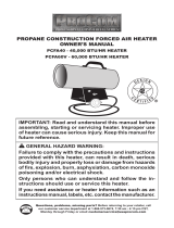
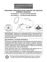
Hot Air Outlet
(Front)
Power Cord
Burn Rate
Adjustment Knob
Burner Assembly Cover
Control Valve Button
Valve Inlet
Adjustable
Foot
Figure 1 - 125,000 & 175,000 Btu/Hr Heater
PRODUCT IDENTIFICATION

www.usaprocom.com
5160495-01A
UNPACKING
1. Remove all packing items applied to
heater for shipment. Keep plastic cover
caps (attached to inlet connector and
hose/regulator assembly) for storage.
2. Remove all items from carton.
3. Check all items for shipping damage. If
heater is damaged, call our customer
service department at 1-866-573-0674.
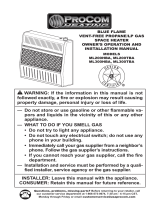
End Cap
Leg Extension
Base Foot
Fastener
Screw
Figure 2 - Foot Assembly
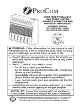
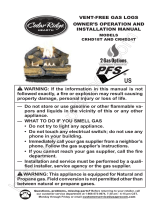
THEORY OF OPERATION
The Fuel System: The hose/regulator assem-
bly attaches to the propane gas supply. The
propane gas moves through the automatic
control valve, burn rate adjustment valve and
out the injector.
The Air System: The motor turns the fan. The
fan pushes air into and around the combustion
chamber. This air is heated and provides a
stream of clean, hot air.
The Ignition System: The high voltage ignitor
sends voltage to the spark ignitor. The spark
ignitor ignites the fuel and air mixture.
The Safety Control System: This system
causes the heater to shut down if the flame
goes out. The motor will continue to run, but
no heat is produced.
Air For
Combustion
Air For
Heating
Cool
Air In
(Back)
Motor
Hose/
Regulator
Assembly
Spark Ignitor
Combustion
Chamber
Figure 3 - Cross Section Operational View
Fan
Clean
Heated
Air Out
(Front)
Power
Cord
Injector
Thermal
Limit Switch
High Voltage Ignitor
Automatic Control Valve
ASSEMBLY
IMPORTANT: Do not use this product without
leg and foot assembly.
Plastic Foot and Leg Extensions
1. Insert leg extensions into outlet end cap
until small hole lines up with larger hole,
visible from inside of outlet end cap (see
Figure 2). Fasten leg extensions with
provided Fastener screws.
2. Insert plastic base foot into each leg ex-
tension and set heater to desired angle.
Small post screws on plastic foot will snap
into holes in leg extensions.

www.usaprocom.com
160495-01A6
Figure 4 - Regulator Position
Propane
Tank
Propane Supply
Valve
Regulator
Hose
POL
Fitting
VENTILATION
WARNING: Review and un-
derstand the warnings in the
Safety, page 3. They are needed
to safely operate this heater. Fol-
low all local codes when using
this heater.
WARNING: Test all gas piping
and connections for leaks after
installation or servicing. Never
use an open ame to check for
a leak. Apply a noncorrosive
leak detection uid to all joints.
Bubbles forming show a leak.
Correct all leaks at once.
1. Provide propane supply system (see
Propane Supply).
2. Connect POL tting on hose/regulator
assembly to propane tank(s). Turn POL
tting counterclockwise into threads on
tank. Tighten rmly using wrench.
IMPORTANT: Position regulator so that
hose leaving the regulator is in a hori-
zontal position (see Figure 4). This places
the regulator vent in the proper position to
protect it from the weather.
WARNING: Follow the mini-
mum fresh, outside air ventila-
tion requirements. If proper
fresh, outside air ventilation is
not provided, carbon monoxide
poisoning can occur. Provide
proper fresh, outside air ventila-
tion before running heater.
WARNING: Provide a fresh
air opening of at least a 3 ft
2
(0.91 m
2
) for each 100,000 Btu/
Hr (105,500 k/j) rating. Provide
extra fresh air if more heaters
are being used.
INSTALLATION
PROPANE SUPPLY
Propane gas and propane tank(s) are to be
furnished by the user.
Use this heater only with a propane vapor
withdrawal supply system. See Chapter 5
of the Standard for Storage and Handling of
Liqueed Petroleum Gas, ANSI/NFPA 58 and/
or CAN/CGA B149.2. Your local library or re
department will have this booklet.
The amount of propane gas ready for use
from propane tanks varies. Two factors decide
this amount:
1. The amount of propane gas in tank(s)
2. The temperature of tank(s)
The chart below shows the number of 100 lb
(45 kg) tanks needed to run this heater.
Average Temp No. Of Tanks
At Tank Location 100 lb (45 kg)
Above 20° F (-7° C) 2
20° F (-7° C) to -0° F (-18° C) 3
Less gas is vaporized at lower temperatures.
You may need a larger tank in colder weather.
Your local propane gas dealer will help you
select the proper supply system.

www.usaprocom.com
7160495-01A
OPERATION
Figure 5 - Hose and Inlet Connector
Hose
Inlet Connector
Gas Valve Button
WARNING: Review and un-
derstand the warnings in the
Safety, page 3. They are needed
to safely operate this heater. Fol-
low all local codes when using
this heater.
TO START HEATER
1. Follow all installation, ventilation and
safety information.
2. Locate heater on stable and level surface.
Make sure strong drafts do not blow into
front or rear of heater.
3. Plug power cord of heater into a three-
prong, grounded extension cord. Exten-
sion cord must be at least 6 feet long.
Extension cord must be UL listed.
Extension Cord Wire Size Requirements
Up to 50 ft (15.24 m) long, use 18 AWG
rated cord.
51 to 100 ft (15.54 to 30.48 m) long, use
16 AWG rated cord.
101 to 200 ft (30.78 to 60.96 m) long, use
14 AWG rated cord.
4. Plug extension cord into a 120 volt/60
hertz, 3-hole, grounded outlet.
5. Open propane supply valve on propane
tank(s) slowly. Note: If not opened slowly,
excess-flow check valve on propane
tank will signicantly reduce gas ow. If
this happens, you may hear a click inside
the regulator assembly and/or notice the
heater burning at a very low heat output.
You will not be able to increase heat output
when you adjust heat setting knob. Do not
run heater in this condition. To reset the
excess ow check valve, close propane/LP
supply valve and open again slowly.
6. Press and hold in gas valve button. Heater
should ignite within a few seconds. Note:
If heater fails to ignite, hose may have air
in it. If so, keep gas valve button pressed
and wait 20 seconds. Release gas valve
button and wait 20 seconds for unburned
fuel to exit heater. Repeat step 6.
7. After heater ignites, wait 30 seconds. This
activates the automatic control system.
Release the gas control valve button.
8. Adjust burn rate with knob.
TO STOP HEATER
1. Tightly close propane supply valve on
propane tank(s).
2. Wait a few seconds. Heater will burn gas
left in supply hose.
3. Unplug heater.
TO RESTART HEATER
1. Wait ve minutes after stopping heater.
2. Repeat steps under To Start Heater.
INSTALLATION
3. Connect hose to valve inlet (see Figure 4,
page 6). Tighten rmly using a wrench.
IMPORTANT: Use extra hose or piping
if needed. Install extra hose or piping
between hose/regulator assembly and
propane tank. You must use the regulator
supplied with heater.
4. Open propane supply valve on propane
tank(s) slowly. Note: If not opened slowly,
excess-ow check valve on propane tank
will signicantly reduce gas ow. If this
happens, you may hear a click inside
the regulator assembly and/or notice the
heater burning at a very low heat output.
You will not be able to increase heat output
when you adjust heat setting knob. Do not
run heater in this condition. To reset the
excess ow check valve, close propane/LP
supply valve and open again slowly.
5. Check all connections for leaks. Apply a
noncorrosive leak detection fluid to gas
joints. Bubbles forming show a leak that
must be corrected.
6. Close propane supply valve.

www.usaprocom.com
160495-01A8
MAINTENANCE
WARNINGS
• Never service heater while it
is plugged in, connected to
propane supply, operating or
hot. Severe burns and electri-
cal shock can occur.
• Keep heater clear and free
from combustible materials,
gasoline and other ammable
vapors and liquids.
• Do not block the ow of com-
bustion or ventilation air.
1. Keep heater clean. Clean heater annually
or as needed to remove dust and debris. If
heater is dirty or dusty, clean heater with
a damp cloth. Use household cleaners on
difcult spots.
2. Inspect heater before each use. Check
connections for leaks. Apply noncorro-
sive leak detection fluid to connections.
Bubbles forming show a leak. Correct all
leaks at once.
3.
Inspect hose/regulator assembly before
each use. If hose is highly worn or cut, re-
place with hose specied by manufacturer.
4. Have heater inspected yearly by a quali-
ed service agency.
5. Keep inside of heater free from combustible
and foreign objects.
6. Clean fan blades each season or as
needed.
SERVICE PROCEDURES
WARNING: Never service
heater while it is plugged in,
connected to propane supply,
operating or hot. Severe burns
and electrical shock can occur.
ELECTRICAL SYSTEM
The entire electrical system for this heater is
contained within the top cover. If any part of
the electrical system is damaged, you must
replace with OEM parts (see page 13).
MOTOR
1. Remove screws on top cover using a
Phillips head screw driver.
2. Remove top cover.
3. Detach the motor and fan wires from ter-
minal block under top cover (see Figure
6, page 9).
4. Remove fan guard from rear of heater.
Fan guard will snap out of shell.
5. Reach into rear of heater shell. Carefully
pull wires through hole in the bracket.
Note: Pull wires through hole one at a time.
6. Remove screws holding motor mount to
shell. Use 5/16" nut driver or Phillips head
screw driver.
7. Carefully pull motor and fan out of shell.
IMPORTANT: Be careful not to damage
fan. Do not set motor and fan down with
the weight resting on fan. This could dam-
age fan pitch.
STORAGE
CAUTION: Disconnect heater
from propane supply tank(s).
1. Store propane tank(s) in safe manner. See
Chapter 5 of Standard for Storage and
Handling of Liqueed Petroleum Gases,
ANSI/NFPA 58. Follow all local codes.
Always store propane tanks outdoors.
2. Place plastic cover caps over brass ttings
on inlet connector and hose/regulator as-
sembly.
3. Store in dry, clean and safe place. Do
not store hose/regulator assembly inside
heater combustion chamber.
4. When taking heater out of storage, always
check inside of heater. Insects and small
animals may place foreign objects in
heater. Keep inside of heater free from
combustible and foreign objects.

www.usaprocom.com
9160495-01A
8. Use hex wrench to loosen set screw which
holds fan to motor shaft (see Figure 7).
Remove fan. Be careful not to damage
the fan blade pitch.
9. Use a nut driver to remove two nuts that
attach motor to motor mounting bracket.
10. Disconnect the green power cord wire
from motor and remove black and white
wire terminals.
11. Discard old motor.
12. Attach green power cord wire to new motor.
13. Replace black and white terminals.
14. Attach new motor to motor mounting
bracket with 2 nuts. Tighten nuts rmly.
15. Place fan onto motor shaft of new mo-
tor. Make sure set screw contacts flat
Terminal
Block
Figure 6 - Removing Fan and Motor
Top
Cover
Motor
Motor Mounting Bracket
Hole in Bracket
SERVICE PROCEDURES
surface on motor shaft. Tighten set screw
rmly (40-50 inch-pounds [46.08-57.60
kilogram-centimeters]).
16. Place motor and fan guard into rear of
heater shell. Make sure power cord is
properly located.
17. Line up mounting holes in shell with
holes on motor mount. Replace 4 screws
through shell and motor mount.
18. Route motor wires through hole in top of
shell (see Figure 6).
19. Reconnect motor and fan wires to the
same posts on terminal block as removed
in step 3, page 8 (see Figure 6).
20. Replace top cover.
21. Replace fan guard.
Figure 7 - Setscrew
Location
Setscrew
FAN
Clean fan every 500 hours of operation or
as needed.
1. Remove screws on top cover using a
Phillips head screw driver.
2. Remove top cover.
3. Detach the 2 black motor wires from ter-
minal block under top cover. Be sure to
detach only wires coming from motor.
4. Remove fan guard from rear of heater.
Fan guard will snap out of shell.
5. Reach into rear of heater shell. Carefully
pull motor wires through hole in bracket.
Note: Pull wires through hole one at a time.
6. Remove screws holding motor mount to
shell. Use 5/16" nut driver or Phillips head
screw driver.

www.usaprocom.com
160495-01A10
SERVICE PROCEDURES
A
Fan
Hub
Setscrew
Motor
Figure 10 - Fan Cross Section
Model Distance A
125 0.5" (12.7 mm)* or
0.9" (22.9 mm)*
175 0.25" (6.4 mm)
Motor
Shaft
* Depending
on Motor Shaft
Figure 9 - Fan, Motor Shaft and Setscrew
Identication
Motor
Shaft
Fan
Setscrew
7. Carefully pull motor and fan out of shell.
IMPORTANT: Be careful not to damage
fan. Do not set motor and fan down with
the weight resting on fan. This could dam-
age fan pitch.
8. Turn motor and fan around. Place motor
and fan into shell backwards. Note: Motor
will go into shell rst (see Figure 8).
9. Line up rear mounting holes in shell with
rst hole on each side of motor mount (see
Figure 8). Note: When holes are lined up,
fan should be outside of shell.
10. Holding mounting screws, carefully reach
through fan blades into rear of heater. Be
careful not to damage fan pitch. Insert
screw through motor mount and shell.
With free hand, attach screw nger tight.
Repeat process for other mounting hole.
11. Use 1/8" hex wrench to loosen setscrew
which holds fan to motor shaft (see Fig-
ure 9).
12. Slip fan off motor shaft.
13. Clean fan using soft cloth moistened with
a cleaning solvent.
14. Dry fan thoroughly.
15. Replace fan on motor shaft. Place set-
screw on flat of shaft. See chart in Figure
10 for distance of fan hub from end of
motor shaft. Tighten setscrew rmly (40-
50 inch-pounds).
16. Remove screws securing motor mount to
shell.
17. Pull motor and fan from shell. Turn motor
and fan around. Carefully place back in
shell. Note: Fan will go into shell rst.
18. Line up mounting holes in shell with
holes on motor mount. Replace 4 screws
through shell and motor mount.
19. Route motor wires through hole in top of
shell (see Figure 6, page 9).
20. Reconnect motor wires to the same posts
on terminal block as removed in step 3,
page 8 (see Figure 6, page 9).
21. Replace top cover.
22. Replace fan guard.
Figure 8 - Fan and Motor Reversed for
Cleaning
Fan
Motor Mounting Bracket

www.usaprocom.com
11160495-01A
Figure 11 - Removing Ignitor Mounting
Screw and Ignitor
Ignitor
Ignitor
Wire
Mounting Screw
Figure 12 - Clearance Between Ignitor
Electrode and Burner
Ignitor Electrode
Gap
Area
SERVICE PROCEDURES
IGNITOR
WARNING: Make sure heater
is disconnected from propane
supply. Heater could ignite caus-
ing severe burns.
1. Remove motor and fan guard from heater
(see page 8, steps 1 through 7).
2. Remove orange ignitor wire from ignitor
electrode.
3. Remove ignitor mounting screw from
rear head using nut-driver or standard
screwdriver (see Figure 11).
4. Remove ignitor from rear head.
5. Install new ignitor. Attach ignitor to rear
head with ignitor mounting screw.
6. Install orange ignitor wire onto quick con-
nect terminal on ignitor electrode.
7. Set gap between ignitor electrode and
burner to 0.17" (43.18 cm) (see Figure 12).
8. Place motor and fan guard into rear
of heater shell (see page 9, steps 16
through 21).

www.usaprocom.com
160495-01A12
TROUBLESHOOTING
WARNING: Never service heater while it is plugged in, connected
to propane supply, operating or hot. Severe burns and electrical
shock can occur.
WARNING: Use only in areas free of high dust content.
Problem Possible Cause Corrective Action
Fan does not turn when
heater is plugged in.
1. No electrical power to heater.
2. Fan hitting inside of heater
shell.
3. Fan blades bent.
4. Defective motor.
1. Check voltage to electrical
outlet. If voltage is good,
check heater power cord for
breaks.
2. Adjust motor/fan guard to
keep fan from hitting inside
of heater shell. Bend fan
guard if necessary.
3.
Replace fan. See Fan, page 8.
4. Replace motor. See Service
Procedures, page 8.
Heater will not ignite. 1. User did not follow installa-
tion or operation instructions
properly.
2. No spark at ignitor. To test
for spark, follow step 8 under
Ignitor, page 11. If you see
spark at ignitor, have heater
serviced by qualied service
person. If no spark seen:
A) Loose or disconnected
ignitor wire
B) Wrong spark gap
C) Piezo ignitor loose
D) Bad ignitor electrode
1. Repeat installation and op-
eration instructions. See
Installation, page 6 and
Operation, page 7.
2. A) Check ignitor wire. Tight-
en or reattach loose ignitor
wire. See Figure 10, page
11 for ignitor wire location
B) Set gap between ignitor
electrode and target plate to
0.17" (0.43 cm)
C) Replace ignitor electrode.
See Ignitor, page 11.
Heater shuts down while
running.
1. High surrounding air tem-
perature causing thermal
limit device to shut down
heater.
2. Restricted air flow.
3. Damaged fan.
4. Excessive dust or debris in
surrounding area.
1. This can happen when run-
ning heater in temperatures
above 85° F (29.44° C). Run
heater in cooler tempera-
tures.
2 Check heater inlet and out-
let. Remove any obstruc-
tions.
3. Replace fan. See Fan, page 8.
4. Clean heater. See Mainte-
nance, page 8.

www.usaprocom.com
13160495-01A
ACCESSORIES
Purchase these accessories from your local dealer. If they can not supply these accessories,
call ProCom Heating, Inc. at 1-866-573-0674 for information.
TECHNICAL SERVICES
You may have further questions about installation, operation, or troubleshooting. If so, contact
ProCom Heating, Inc. at 1-866-573-0674. When calling please have your model and serial
numbers of your heater ready.
You can also visit ProCom Heating, Inc.’s web site at www.usaprocom.com.
WIRING DIAGRAM
160518-01A
Black** or Orange**/
Negro** o Naranja**/
Noir** ou orange**
L1
L2
White/Blanco/
Blanc
Blue*/Azul*/Bleu*
Blue*/Azul*/Bleu*
Blue/Azul/Bleu
White/Blanco/
Blanc
White/Blanco/Blanc
Black/
Negro/Noir
Black/Negro/Noir
Black/Negro/Noir
Black/Negro/Noir
Green/
Verde/
Vert
Orange/
Naranja
Orange/
Naranja
Orange/
Naranja
Orange/
Naranja
Thermocouple/Termopar
CONNECTION DIAGRAM/DIAGRAMA DE CONEXIONES/
DIAGRAMME DE CONNEXION
SCHEMATIC DIAGRAM/DIAGRAMA ESQUEMÁTICO/
DIAGRAMME DE CIRCUIT
60,000/125,000/175,000 Models/Modelos
Relay/Relé/Relais
Motor/
Moteur
Ignitor/
Encendedor/
Allumeur
High-Limit Switch/
Interruptor de
límite alto/
Commutateur de
limite supérieure
• If any original wiring as supplied with the heater must be replaced, it must be replaced with type AWG 105° C
wire or its equivalent except as indicated (*Type SF2-200. **UL Style 3257 250° C)
• Si es necesario reemplazar algún cable suministrado originalmente con el calentador, éste se debe reemplazar con
cable tipo AWG 105° C o su equivalente, excepto cuando se indica lo contrario (*Tipo SF2-200. **UL Style 3257 250° C)
* Si le câblage fourni avec l'appareil de chauffage doit être remplacé, faites-le avec du câble de type AWG 105° C
ou son équivalent, sauf indication contraire (*Type SF2-200. **UL Style 3257 250° C)
Line Cord/
Cable de línea/
Cordon électrique
Motor/
Moteur
High Limit Switch/
Interruptor de límite alto/
Interrupteur de
limite supérieure
White/Blanco/Blanc
Black/Negro/Noir
115V
60HZ
Gas
Valve
Relay/
Relé/
Relais
Thermocouple/
Termopar
Green/Verde/Vert
L1
L2
Ignitor/
Encendedor/
Allumeur
Válvula de gas/
Robinet de gaz
Electrode/Electrodo/
Électrode
Electrode/Electrodo/
Électrode
• Label all wires prior to disconnecting.
REPLACEMENT PARTS
Note: Use only original replacement parts. This will protect your warranty coverage for parts
replaced under warranty.
PARTS NOT UNDER WARRANTY
Contact authorized dealers of this product.
If they can’t supply original replacement
part(s) call Customer Service toll free at
1-866-573-0674 for referral information.
When calling Customer Service have ready:
• Model number of your heater
• The replacement part number
PARTS UNDER WARRANTY
Contact authorized dealers of this product.
If they can’t supply original replacement
parts, call Customer Service toll free at
1-866-573-0674 for referral information.
When calling Customer Service or your
dealer, have ready:
• Your name
• Your address
• Model and serial number of your heater
• How heater was malfunctioning
• Type of gas supply and Propane/LP tank
size
• Purchase date
Usually, we will ask you to return the defective
part to the factory

www.usaprocom.com
15160495-01A
PARTS
MODELS PCFA125V AND PCFA175V
This list contains replaceable parts used in your heater. When ordering parts, follow the
instructions listed under Replacement Parts on page 13 of this manual.
Item PCFA125V PCFA175V Description Qty
1 ** ** Shell 1
2 ** ** Combustion Chamber 1
3 160504-01 160504-01 Cage Tube 4
4 ** ** End Cap 2
5 160238-01 160238-01 Fastener Screw 2
6 160497-01 160497-01 Fan Guard 1
7 160503-01 160503-01 Foot Tube 2
8 160502-01 160502-01 Base Foot 1
9 160482-02 160482-02 Burner Assembly 1
10 160510-01 160523-01 Rear Plate 1
11 160481-02 160481-02 Ignitor Electrode 1
12 160102-03 160102-03 Screw, HWH AB 8-32 x 0.38 1
13 160440-03 160440-04 Thermostat Switch 1
14 160441-02 160441-02 Screw, Thermal Hex 4-40 x 1/4 1
15 160449-02 160449-02 Thermocouple 1
16 160505-01 160524-01 Fan 1
17 160499-01 160525-01 Motor 1
18 160500-01 160500-01 Motor Bracket 1
19 160318-01 160318-01 Power Cord 1
20 PF06-1201-D PF06-1201-D Strain Relief Bushing 1
21 160477-01 160477-01 Brass Adaptor 1
22 160476-01 160476-01 Control Valve 1
23 160509-01 160509-01 Brass Elbow 1/4 NPT Female/Male 2
24 160294-03 160294-04 Ball Valve Assembly 1
25 160478-01 160478-01 Brass Fitting, 1/4 NPT 1
26 160304-01 160304-01 Control Knob 1
27 160480-05 160480-05 Tube 1
28 160474-02 160474-03 Injector 1
29 160508-01 160508-01 Female Elbow 1
30 160483-01 160483-01 Terminal Block 1
31 160485-01 160485-01 Ignitor Assembly 1
32 160479-01 160479-01 Relay Assembly 1
PARTS AVAILABLE - NOT SHOWN
160519-01 160519-01 Operation Decal 1
160493-01 160493-02 Model Data Decal 1
160518-01 160518-01 Wiring Diagram Decal 1
160468-01 160468-01 Hose/Regulator Assembly 1
** Not a eld replaceable part.

160495-01
Rev. A
07/13
REGISTER YOUR PRODUCT AT WWW.USAPROCOM.COM
IMPORTANT: We urge you to register your product within 10 days of date of installation, complete
with entire serial number which can be found on the rating plate. Please ll out the warranty infor-
mation above for your personal records. Retain this manual for future reference.
Always specify model and serial numbers when communicating with customer service.
We reserve the right to amend these specications at any time without notice. The only warranty applicable
is our standard written warranty. We make no other warranty, expressed or implied.
LIMITED WARRANTY
ProCom Heating, Inc. warrants this product to be free from defects in materials and components for ONE
(1) year from the date of rst purchase, provided that the product has been properly installed by a qualied
installer in accordance with all local codes and instructions furnished with the unit, operated and main-
tained in accordance with all applicable instructions. To make a claim under this warranty, the Bill of Sale
or cancelled check must be presented.
RESPONSIBILITY OF OWNER
This warranty is extended only to the original retail purchaser. This warranty covers the cost of part(s)
required to restore this heater to proper operating condition. Warranty part(s) MUST be obtained through
ProCom Heating, Inc. who will provide original factory replacement parts. Failure to use original factory
replacement parts voids this warranty. The heater MUST be installed by a qualied installer in accordance
with all local codes and instructions furnished with the unit.
WHAT IS NOT COVERED
This warranty does not apply to parts that are not in original condition because of normal wear and tear or
parts that fail or become damaged as a result of misuse, accidents, lack of proper maintenance or defects
caused by improper installation. Travel, diagnostic cost, labor, transportation and any and all such other
costs related to repairing a defective heater will be the responsibility of the owner.
TO THE FULL EXTENT ALLOWED BY THE LAW OF THE JURISDICTION THAT GOVERNS THE SALE
OF THE PRODUCT, THIS EXPRESS WARRANTY EXCLUDES ANY AND ALL OTHER EXPRESSED
WARRANTIES AND LIMITS THE DURATION OF ANY AND ALL IMPLIED WARRANTIES. INCLUDING
WARRANTIES OF MERCHANTABILITY AND FITNESS FOR A PARTICULAR PURPOSE TO TWO (2)
YEARS ON ALL COMPONENTS FROM THE DATE OF FIRST PURCHASE. PROCOM HEATING, INC.'S
LIABILITY IS HEREBY LIMITED TO THE PURCHASE PRICE OF THE PRODUCT AND PROCOM HEAT-
ING, INC. SHALL NOT BE LIABLE FOR ANY OTHER DAMAGES WHATSOEVER INCLUDING INDIRECT.
INCIDENTAL OR CONSEQUENTIAL DAMAGES.
Some states do not allow a limitation on how long an implied warranty lasts or an exclusion or limitation of
accidental or consequential damages, the above limitation on implied warranties, or exclusion or limitation
on damages may not apply to you.
This warranty gives you specic legal right, and you may also have other rights that vary from state to state.
WARRANTY
KEEP THIS WARRANTY
Model _______________________________
Serial No. ____________________________
Date Purchased _______________________
Keep receipt for warranty verication.
ProCom Heating, Inc.
Bowling Green, KY 42101
www.usaprocom.com
1-866-573-0674

www.usaprocom.com
29160495-01A
PROCEDIMIENTOS DE SERVICIO
Figura 12 - Distancia mínima entre el
electrodo del encendido y del quemador
Electrodo del
encendido
Área de la
separación
DIAGRAMA DE CABLEADO
160518-01A
Black** or Orange**/
Negro** o Naranja**/
Noir** ou orange**
L1
L2
White/Blanco/
Blanc
Blue*/Azul*/Bleu*
Blue*/Azul*/Bleu*
Blue/Azul/Bleu
White/Blanco/
Blanc
White/Blanco/Blanc
Black/
Negro/Noir
Black/Negro/Noir
Black/Negro/Noir
Black/Negro/Noir
Green/
Verde/
Vert
Orange/
Naranja
Orange/
Naranja
Orange/
Naranja
Orange/
Naranja
Thermocouple/Termopar
CONNECTION DIAGRAM/DIAGRAMA DE CONEXIONES/
DIAGRAMME DE CONNEXION
SCHEMATIC DIAGRAM/DIAGRAMA ESQUEMÁTICO/
DIAGRAMME DE CIRCUIT
60,000/125,000/175,000 Models/Modelos
Relay/Relé/Relais
Motor/
Moteur
Ignitor/
Encendedor/
Allumeur
High-Limit Switch/
Interruptor de
límite alto/
Commutateur de
limite supérieure
• If any original wiring as supplied with the heater must be replaced, it must be replaced with type AWG 105° C
wire or its equivalent except as indicated (*Type SF2-200. **UL Style 3257 250° C)
• Si es necesario reemplazar algún cable suministrado originalmente con el calentador, éste se debe reemplazar con
cable tipo AWG 105° C o su equivalente, excepto cuando se indica lo contrario (*Tipo SF2-200. **UL Style 3257 250° C)
* Si le câblage fourni avec l'appareil de chauffage doit être remplacé, faites-le avec du câble de type AWG 105° C
ou son équivalent, sauf indication contraire (*Type SF2-200. **UL Style 3257 250° C)
Line Cord/
Cable de línea/
Cordon électrique
Motor/
Moteur
High Limit Switch/
Interruptor de límite alto/
Interrupteur de
limite supérieure
White/Blanco/Blanc
Black/Negro/Noir
115V
60HZ
Gas
Valve
Relay/
Relé/
Relais
Thermocouple/
Termopar
Green/Verde/Vert
L1
L2
Ignitor/
Encendedor/
Allumeur
Válvula de gas/
Robinet de gaz
Electrode/Electrodo/
Électrode
Electrode/Electrodo/
Électrode
5. Instale el encendido nuevo. Fije el encen-
dido a la cabeza posterior con el tornillo
de montaje del encendido.
6. Instale el cable del encendedor de color
naranja en el terminal de conexión rápida
en el electrodo de encendido.
7. Ajuste la distancia entre el electrodo del
encendido y del quemador a 4.3 mm
(0.17") (consulte la gura 12).
8. Coloque el motor y el resguardo del ven-
tilador en la parte posterior de la cubierta
del calentador (consulte página 27, pasos
16-21).

www.usaprocom.com
47160495-01A
PROCÉDURES D'ENTRETIEN
Figure 12 - Espace entre l'électrode
d'allumage et le brûleur
Électrode
d'allumage
Espace
7. Assurez-vous que l'espace entre l'élec-
trode d'allumage et le brûleur 43,18 mm
(0,17 po) (voir gure 12).
8. Installez le moteur et la grille du ventilateur
à l'arrière de l'habillage de l'appareil de
chauffage (voir page 44, étapes 16-21).
SCHÉMA DE CÂBLAGE
160518-01A
Black** or Orange**/
Negro** o Naranja**/
Noir** ou orange**
L1
L2
White/Blanco/
Blanc
Blue*/Azul*/Bleu*
Blue*/Azul*/Bleu*
Blue/Azul/Bleu
White/Blanco/
Blanc
White/Blanco/Blanc
Black/
Negro/Noir
Black/Negro/Noir
Black/Negro/Noir
Black/Negro/Noir
Green/
Verde/
Vert
Orange/
Naranja
Orange/
Naranja
Orange/
Naranja
Orange/
Naranja
Thermocouple/Termopar
CONNECTION DIAGRAM/DIAGRAMA DE CONEXIONES/
DIAGRAMME DE CONNEXION
SCHEMATIC DIAGRAM/DIAGRAMA ESQUEMÁTICO/
DIAGRAMME DE CIRCUIT
60,000/125,000/175,000 Models/Modelos
Relay/Relé/Relais
Motor/
Moteur
Ignitor/
Encendedor/
Allumeur
High-Limit Switch/
Interruptor de
límite alto/
Commutateur de
limite supérieure
• If any original wiring as supplied with the heater must be replaced, it must be replaced with type AWG 105° C
wire or its equivalent except as indicated (*Type SF2-200. **UL Style 3257 250° C)
• Si es necesario reemplazar algún cable suministrado originalmente con el calentador, éste se debe reemplazar con
cable tipo AWG 105° C o su equivalente, excepto cuando se indica lo contrario (*Tipo SF2-200. **UL Style 3257 250° C)
* Si le câblage fourni avec l'appareil de chauffage doit être remplacé, faites-le avec du câble de type AWG 105° C
ou son équivalent, sauf indication contraire (*Type SF2-200. **UL Style 3257 250° C)
Line Cord/
Cable de línea/
Cordon électrique
Motor/
Moteur
High Limit Switch/
Interruptor de límite alto/
Interrupteur de
limite supérieure
White/Blanco/Blanc
Black/Negro/Noir
115V
60HZ
Gas
Valve
Relay/
Relé/
Relais
Thermocouple/
Termopar
Green/Verde/Vert
L1
L2
Ignitor/
Encendedor/
Allumeur
Válvula de gas/
Robinet de gaz
Electrode/Electrodo/
Électrode
Electrode/Electrodo/
Électrode
/