Electro-Voice CPS2.4 User manual
- Category
- Supplementary music equipment
- Type
- User manual
Page is loading ...
Page is loading ...

CONTRACTOR PRECISION SERIES
3
CONTENTS
Introduction . . . . . . . . . . . . . . . . . . . . . . . . . . . . . . . . . . . . . . . . . . . . . . . . . . . . . . . . . . . . . . . . . 5
Welcome . . . . . . . . . . . . . . . . . . . . . . . . . . . . . . . . . . . . . . . . . . . . . . . . . . . . . . . . . . . . . . . . . . . . . . . 5
Unpacking and Inspection. . . . . . . . . . . . . . . . . . . . . . . . . . . . . . . . . . . . . . . . . . . . . . . . . . . . . . . . . . 5
Scope of Delivery and Warranty . . . . . . . . . . . . . . . . . . . . . . . . . . . . . . . . . . . . . . . . . . . . . . . . . . . . . 5
Features and Description . . . . . . . . . . . . . . . . . . . . . . . . . . . . . . . . . . . . . . . . . . . . . . . . . . . . . . . . . . 5
Responsibility of the User . . . . . . . . . . . . . . . . . . . . . . . . . . . . . . . . . . . . . . . . . . . . . . . . . . . . . . . . . . 5
Installation . . . . . . . . . . . . . . . . . . . . . . . . . . . . . . . . . . . . . . . . . . . . . . . . . . . . . . . . . . . . . . . . . . 7
Controls, Indicators and Connections . . . . . . . . . . . . . . . . . . . . . . . . . . . . . . . . . . . . . . . . . . . . . . . . . 7
Operating Voltage . . . . . . . . . . . . . . . . . . . . . . . . . . . . . . . . . . . . . . . . . . . . . . . . . . . . . . . . . . . . . . . . 8
Mains Switch . . . . . . . . . . . . . . . . . . . . . . . . . . . . . . . . . . . . . . . . . . . . . . . . . . . . . . . . . . . . . . . . . . . . 8
Mounting . . . . . . . . . . . . . . . . . . . . . . . . . . . . . . . . . . . . . . . . . . . . . . . . . . . . . . . . . . . . . . . . . . . . . . . 8
Ventilation . . . . . . . . . . . . . . . . . . . . . . . . . . . . . . . . . . . . . . . . . . . . . . . . . . . . . . . . . . . . . . . . . . . . . . 8
Groundlift. . . . . . . . . . . . . . . . . . . . . . . . . . . . . . . . . . . . . . . . . . . . . . . . . . . . . . . . . . . . . . . . . . . . . . . 9
High Pass Filter (HPF) . . . . . . . . . . . . . . . . . . . . . . . . . . . . . . . . . . . . . . . . . . . . . . . . . . . . . . . . . . . . 9
Power on delay . . . . . . . . . . . . . . . . . . . . . . . . . . . . . . . . . . . . . . . . . . . . . . . . . . . . . . . . . . . . . . . . . . 9
Selecting the Mode Of Operation and Audio Output Cabeling . . . . . . . . . . . . . . . . . . . . . . . . . . . . . . 10
Audio Input Cabeling. . . . . . . . . . . . . . . . . . . . . . . . . . . . . . . . . . . . . . . . . . . . . . . . . . . . . . . . . . . . . . 11
Operation . . . . . . . . . . . . . . . . . . . . . . . . . . . . . . . . . . . . . . . . . . . . . . . . . . . . . . . . . . . . . . . . . . . 12
Volume Control . . . . . . . . . . . . . . . . . . . . . . . . . . . . . . . . . . . . . . . . . . . . . . . . . . . . . . . . . . . . . . . . . . 12
Indications . . . . . . . . . . . . . . . . . . . . . . . . . . . . . . . . . . . . . . . . . . . . . . . . . . . . . . . . . . . . . . . . . . . . . . 12
Standby Mode (POWER REMOTE) . . . . . . . . . . . . . . . . . . . . . . . . . . . . . . . . . . . . . . . . . . . . . . . . . . 13
Fan Cooling. . . . . . . . . . . . . . . . . . . . . . . . . . . . . . . . . . . . . . . . . . . . . . . . . . . . . . . . . . . . . . . . . . . . . 13
Options . . . . . . . . . . . . . . . . . . . . . . . . . . . . . . . . . . . . . . . . . . . . . . . . . . . . . . . . . . . . . . . . . . . . . 14
RCM-810. . . . . . . . . . . . . . . . . . . . . . . . . . . . . . . . . . . . . . . . . . . . . . . . . . . . . . . . . . . . . . . . . . . . . . . 14
INHALT
Einführung . . . . . . . . . . . . . . . . . . . . . . . . . . . . . . . . . . . . . . . . . . . . . . . . . . . . . . . . . . . . . . . . . . 19
Willkommen. . . . . . . . . . . . . . . . . . . . . . . . . . . . . . . . . . . . . . . . . . . . . . . . . . . . . . . . . . . . . . . . . . . . . 19
Auspacken und Inspektion . . . . . . . . . . . . . . . . . . . . . . . . . . . . . . . . . . . . . . . . . . . . . . . . . . . . . . . . . 19
Lieferumfang und Garantie . . . . . . . . . . . . . . . . . . . . . . . . . . . . . . . . . . . . . . . . . . . . . . . . . . . . . . . . . 19
Eigenschaften & Beschreibung . . . . . . . . . . . . . . . . . . . . . . . . . . . . . . . . . . . . . . . . . . . . . . . . . . . . . . 19
Verantwortung des Betreibers. . . . . . . . . . . . . . . . . . . . . . . . . . . . . . . . . . . . . . . . . . . . . . . . . . . . . . . 19
Installation . . . . . . . . . . . . . . . . . . . . . . . . . . . . . . . . . . . . . . . . . . . . . . . . . . . . . . . . . . . . . . . . . . 20
Bedienelemente, Anzeigen und Anschlüsse. . . . . . . . . . . . . . . . . . . . . . . . . . . . . . . . . . . . . . . . . . . . 20
Betriebsspannung . . . . . . . . . . . . . . . . . . . . . . . . . . . . . . . . . . . . . . . . . . . . . . . . . . . . . . . . . . . . . . . . 21
Netzschalter . . . . . . . . . . . . . . . . . . . . . . . . . . . . . . . . . . . . . . . . . . . . . . . . . . . . . . . . . . . . . . . . . . . . 21
Einbau . . . . . . . . . . . . . . . . . . . . . . . . . . . . . . . . . . . . . . . . . . . . . . . . . . . . . . . . . . . . . . . . . . . . . . . . . 21
Kühlung . . . . . . . . . . . . . . . . . . . . . . . . . . . . . . . . . . . . . . . . . . . . . . . . . . . . . . . . . . . . . . . . . . . . . . . . 21
Groundlift. . . . . . . . . . . . . . . . . . . . . . . . . . . . . . . . . . . . . . . . . . . . . . . . . . . . . . . . . . . . . . . . . . . . . . . 22
Hochpassfilter (HPF). . . . . . . . . . . . . . . . . . . . . . . . . . . . . . . . . . . . . . . . . . . . . . . . . . . . . . . . . . . . . . 22
Einschaltverzögerung . . . . . . . . . . . . . . . . . . . . . . . . . . . . . . . . . . . . . . . . . . . . . . . . . . . . . . . . . . . . . 22
Betriebsart (MODE) und Verkabelung des Audio-Ausgangs . . . . . . . . . . . . . . . . . . . . . . . . . . . . . . . 23
Verkabelung des Audio-Eingangs . . . . . . . . . . . . . . . . . . . . . . . . . . . . . . . . . . . . . . . . . . . . . . . . . . . . 24
Betrieb . . . . . . . . . . . . . . . . . . . . . . . . . . . . . . . . . . . . . . . . . . . . . . . . . . . . . . . . . . . . . . . . . . . . . 25
Eingangspegel-Regler. . . . . . . . . . . . . . . . . . . . . . . . . . . . . . . . . . . . . . . . . . . . . . . . . . . . . . . . . . . . . 25
Anzeigen . . . . . . . . . . . . . . . . . . . . . . . . . . . . . . . . . . . . . . . . . . . . . . . . . . . . . . . . . . . . . . . . . . . . . . . 25
Standby-Modus (POWER REMOTE) . . . . . . . . . . . . . . . . . . . . . . . . . . . . . . . . . . . . . . . . . . . . . . . . . 26
Lüfter . . . . . . . . . . . . . . . . . . . . . . . . . . . . . . . . . . . . . . . . . . . . . . . . . . . . . . . . . . . . . . . . . . . . . . . . . . 26
Optionen. . . . . . . . . . . . . . . . . . . . . . . . . . . . . . . . . . . . . . . . . . . . . . . . . . . . . . . . . . . . . . . . . . . . 27
RCM-810. . . . . . . . . . . . . . . . . . . . . . . . . . . . . . . . . . . . . . . . . . . . . . . . . . . . . . . . . . . . . . . . . . . . . . . 27
Specifications/Technische Daten . . . . . . . . . . . . . . . . . . . . . . . . . . . . . . . . . . . . . . . . . . . . . . . 30
Mains Operation & Resulting Temperature. . . . . . . . . . . . . . . . . . . . . . . . . . . . . . . . . . . . . . . . . . . . . 31
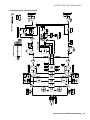
Block Diagram / Blockschaltbild . . . . . . . . . . . . . . . . . . . . . . . . . . . . . . . . . . . . . . . . . . . . . . . . . . . . . 33
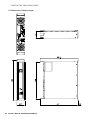
Dimensions / Abmessungen . . . . . . . . . . . . . . . . . . . . . . . . . . . . . . . . . . . . . . . . . . . . . . . . . . . . . . . . 34

4 Owner‘s Manual
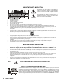
IMPORTANT SAFETY INSTRUCTIONS
1. Read these instructions.
2. Keep these instructions.
3. Heed all warnings.
4. Follow all instructions.
5. Do not use this apparatus near water.
6. Clean only with a dry cloth.
7. Do not cover any ventilation openings. Install in accordance with the manufacture’s instructions.
8. Do not install near heat sources such as radiators, heat registers, stoves, or other apparatus (including amplifiers) that produce heat.
9. Do not defeat the safety purpose of the polarized or the grounding-type plug. A polarized plug has two blades with one wider than the other.
A grounding type plug has two blades and a third grounding prong. The wide blade or the third prong are provided for your safety. I the
provided plug does not fit into your outlet, consult an electrician for replacement of the obsolete outlet.
10. Protect the power cord from being walked on or pinched particularly at plugs, convenience receptacles, and the point where they exit from
the apparatus.
11. Only use attachments/accessories specified by the manufacturer.
12. Use only with the cart, tripod, bracket, or table specified by the manufacturer, or sold with the apparatus. When a cart is used, use caution
when moving the cart/apparatus combination to avoid injury from tip-over.
13. Unplug this apparatus during lightning storms or when unused for a long period of time.
14. Refer all servicing to qualified service personnel. Servicing is required when the apparatus has been damaged in any way, such as power-
supply cord or plug is damaged, liquid has been spilled or orbjects have fallen into the apparatus, the apparatus has been exposed to rain
or moisture, does not operate normally, or has been dropped.
15. Do not expose this equipment to dripping or splashing and ensure that no objects filled with liquids, such as vases, are placed on the
equipment.
16. To completely disconnect this equipment from the AC Mains, disconnect the power supply cord plug from the AC receptacle.
17. The mains plug of the power supply cord shall remain readily operable.
IMPORTANT SERVICE INSTRUCTIONS
CAUTION: These servicing instructions are for use by qualified personnel only. To reduce the risk of electric shock, do not
perform any servicing other than that contained in the Operating Instructions unless you are qualified to do so.
Refer all servicing to qualified service personnel.
1. Security regulations as stated in the EN 60065 (VDE 0860 / IEC 65) and the CSA E65 - 94 have to be obeyed when servicing the appliance.
2. Use of a mains separator transformer is mandatory during maintenance while the appliance is opened, needs to be operated and is
connected to the mains.
3. Switch off the power before retrofitting any extensions, changing the mains voltage or the output voltage.
4. The minimum distance between parts carrying mains voltage and any accessible metal piece (metal enclosure), respectively between the
mains poles has to be 3 mm and needs to be minded at all times. The minimum distance between parts carrying mains voltage and any
switches or breakers that are not connected to the mains (secondary parts) has to be 6 mm and needs to be minded at all times.
5. Replacing special components that are marked in the circuit diagram using the security symbol (Note) is only permissible when using
original parts.
6. Altering the circuitry without prior consent or advice is not legitimate.
7. Any work security regulations that are applicable at the locations where the appliance is being serviced have to be strictly obeyed. This
applies also to any regulations about the work place itself.
8.
All instructions concerning the handling of MOS-circuits have to be observed
.
WEEE RECYCLING/DISPOSAL INSTRUCTIONS
The lightning flash with arrowhead symbol, within an
equilateral triangle is intended to alert the user to the
presence of uninsulated „dangerous voltage“ within the
product’s enclosure that may be of sufficent magnitude
to constitute a risk of electric shock to persons.
The exclamation point within an equilateral triangle is
intended to alert the user to the presence of important
operating and maintance (servicing) instructions in the
literature accompanying the appliance.
NOTE: SAFETY COMPONENT (MUST BE REPLACED BY ORIGINAL PART)
The Wheelie Bin symbol found on the product or in the manual indicates that this product must not be dis-
posed of with other waste. It is in our category the manufacturer’s responsibility to properly dispose of their
waste electrical and electronic equipment (WEEE) at the end of its life. Due to the differences in each EU
country’s management of WEEE, please contact your local distributor. We are committed to facilitate our own
electronic-waste-management-system, for the free of charge return of all EVI Audio GmbH products: Telex,
Dynacord, ElectroVoice, Midas Consoles, KlarkTeknik and RTS. Arrangements are made with the dealer
where you purchased the equipment from, for the returning of all unusable equipment at no cost, to the fac-
tory in Straubing, for environmental protective disposal.

CONTRACTOR PRECISION SERIES
Owner‘s Manual 5
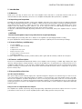
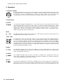
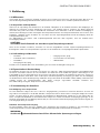
1 Introduction
1.1 Welcome
Thank you for choosing an Electro-Voice CPS series amplifier. Please take time to consult this manual so that you can
understand all the features built into your Electro-Voice amplifier and fully utilize all its performance capabilities.
1.2 Unpacking and Inspection
Carefully open the packaging and take out the power amplifier. Inspect the power amp’s enclosure for damages that might
have happened during transportation. Each amplifier is examined and tested in detail before leaving the manufacturing site to
ensure that it arrives in perfect condition at your place. Please inform the transport company immediately, if the power
amplifier shows any damage. Being the addressee, you are the only person who can claim damages in transit. Keep the
cardboard box and all packaging materials for inspection by the transport company.
Keeping the cardboard box including all packing materials is also recommended, if the power amplifier shows no external
damages.
When shipping the power amp, make sure to always use its original box and packaging materials. Packing
the power amplifier like it was packed by the manufacturer guarantees optimum protection from transport damage.
1.3 Scope of Delivery and Warranty
• 1 Power Amplifier
• 1 Owner‘s Manual (this document)
• 1 Mains Cord
• 1 Output connector, 4 pole
• 2 Input connector, 3 pole
• 1 Power Remote connector, 2 pole
• 1 Warranty Certificate
Keep the original invoice that states the purchase/delivery date together with the warranty certificate at a safe place.
1.4 Features and Description
Electro-Voice CONTRACTOR PRECISION SERIES Series amplifiers offer a package of reliable high output power, high
efficiency and legendary pro audio performance. They are the premium choice as system drive for a variety of Electro-Voice‘s
installation loudspeakers like e.g. EVI, FRi, FRX or Variplex families. Their comprehensive protection system includes circuitry
against overheating, overload, short circuit, HF and DC as well as back-EMF and inrush current. Loudspeakers are protected
by turn-on-delay relays.
1.5 Responsibility of the User
Speaker System Damage
CPS power amps provide extremely high power output that might be dangerous for human beings as well as for the
connected speaker systems. High output voltages can damage or even destroy the connected speaker systems, especially,
when the CPS amplifier is operated in bridged mode. Prior to connecting any loudspeakers, make sure to check the speaker
system’s specifications for continuous and peak power handling capacities. Even if amplification has been reduced through
lowering the input level controls on the amplifier’s front panel, it is still possible to achieve full power output with a sufficiently
high input signal.
Danger at the Loudspeaker/Power Outputs
CPS amplifiers are capable of producing dangerously high voltage output that is present at the output connectors. To protect
yourself from electric shock, do not touch any blank speaker cables during operation of the power amp.
CAUTION:
Do not ship the power amp in any other but its original packaging.

CONTRACTOR PRECISION SERIES
6 Owner‘s Manual
HF-Interference (FCC Information USA)
1. IMPORTANT: Do not modify this unit! Changes or modifications not expressly approved by the manufacturer could void the
user‘s authority, granted by the FCC, to operate the equipment.
2. NOTE:This equipment has been tested and found to comply with the limits for a Class A digital device, pursuant to Part 15
of the FCC Rules. These limits are designed to provide reasonable protection agains harmful interference in a residential
installation. This equipment generates, uses and can radiate radio frequency energy and, if not installed and used in
accordance with the instructions, may cause harmful interference to radio communications. However, there is no guarantee
that interference will not occur in a particular installation. If this equipment does cause harmful interference to radio or
television reception, which can be
determined by turning the equipment off and on, the user is encouraged to try to correct the interference by
one or more of the following measures:
• Reorient or relocate the receiving antenna
• Increase the separation between the equipment and receiver
• Connect the equipment into an outlet on a circuit different from that to which the receiver is connected
• Consult the dealer or an experienced radio/TV technician for help
This Class A digital apparatus complies with Canadian ICES-003.
Cat appareil numérique de la classe A est conforme à la norme NMB-003 du Canada.
WARNING:
The terminals marked with are hazardous live and the external wiring connected to these
terminals requires installation by an instructed person or the use of ready-made leads of
cords.
This is a Class A product. In a domestic environment this product may cause radio inter-
ferences in which case the user may be required to take adequate measures.

CONTRACTOR PRECISION SERIES
Owner‘s Manual 7
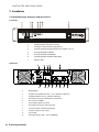
2 Installation
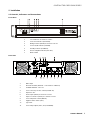
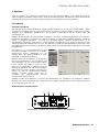
2.1 Controls, Indicators and Connections
Front View
Rear View
1 Level Indicators for channels 1 and 2
2 Protections Indicator (PROTECT)
3 Muting Indicator (MUTE) for channels 1 and 2
4 Power On/Off Indicator (POWER)
5 Standby Indicator (STANDBY)
6 Remote Amplifier Indicator (IRIS-Net)
7 Mains Switch
1 Mains Input
2
Ground Lift Switch (CIRCUIT
⊥ TO CHASSIS SWITCH)
3 POWER REMOTE connector
4 Power On Delay selection switch (ON DELAY)
5 Expansion Slot
6 Audio Inputs (INPUT) for channels 1 and 2
7 Input Level Control (LEVEL) for channels 1 and 2
8 Power Amp Mode Switch (MODE)
9 Highpass Filter Switch (HPF)
10 Type Plate
11 Power Amp Outputs (CH 1, CH 2, BRIDGED)

CONTRACTOR PRECISION SERIES
8 Owner‘s Manual
2.2 Operating Voltage
The power amplifier receives its power supply via the MAINS IN connector. Only the provided power cord may be used.
During installation, always separate the power amplifier from the mains. Connect the power amplifier only to a mains network,
which corresponds to the requirements indicated on the type plate.
Mains Operation & Resulting Temperature
The power drawn from the mains network is converted into output power to feed the connected loudspeaker systems and into
heat. The difference between power consumption and dispensed power is called power dissipation (P
d
). The amount of heat
resulting from power dissipation might remain inside of a rack-shelf and needs to be diverted using appropriate measures.
The tables on page 31 allow the determination of power supply and cabling requirements. The tables are meant as auxiliary
means for calculating temperatures inside of a rack-shelf system/cabinet and the ventilation efforts necessary.
The column P
d
lists the leakage power in relation to different operational states. The column BTU/hr lists the dispensed heat
amount per hour. Power consumption is direct proportional for other mains voltages. The following conversion factors are
meant for easy conversion: 100V = 2.3; 120V = 1.9; 240V = 0.96
2.3 Mains Switch
The Mains Switch on the front panel separates the power amp from the mains. Turning the
Mains Switch to ON starts booting up the power amp. A soft start circuit compensates
mains inrush current peaks and thus prevents triggering AC mains fuse when switching on
the amplifier. Speaker system switch-on is delayed by approximately 2 seconds via output
relays, effectively suppressing any possible power-on noise, which otherwise might be
heard through the loudspeakers. PROTECT-LED light and fans are at high speed during
this delay. This indicates all protections are working fine.
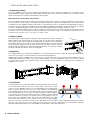
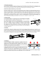
2.4 Mounting
CPS amplifiers have been designed for installation in a conventional 19-inch rack case. Attach the power amp with its frontal
rack mount ears using 4 screws and washers as shown in following illustration.
Additionally securing the amplifier at the rear becomes necessary, if the rack case in which the power amplifier has been
installed will be transported. Failure to do so may result in damage to the power amplifier as well as to the rack case. Attach
the power amp as shown in the illustration using 4 case nuts and screws. Brackets for securing the power amplifier are
available as accessories.
2.5 Ventilation
As with all Electro-Voice power amps with fan cooling, the airflow direction is front-
to-rear, obviously because there is more cold air outside of the rack case than
inside. The power amplifier remains cooler and dissipating the developing waste
heat in a specific direction gets easier. In general, setting up or mounting the
power amplifier has to be done in a way that fresh air can enter unhindered at the
front and exhausted air can exit at the rear. When installing the power amp in a
case or rack system, attention should be paid to these details to provide sufficient
ventilation. Allow for an air duct of at least 60 mm x 330 mm between the rear
panel of the power amplifier and the inner wall of the cabinet/rack case. Make
sure that the duct reaches up to the cabinet’s or the rack case’s top ventilation
louvers. Leave room of at least 100 mm above the cabinet/rack case for ventilation. Since temperatures inside of the cabinet/
rack case can easily rise up to 40 °C during operation of the power amp, it is mandatory to bear in mind the maximum
allowable ambient temperature for all other appliances installed in the same cabinet/rack case.

CONTRACTOR PRECISION SERIES
Owner‘s Manual 9
For fixed amplifier installations in a device control room that incorporate a central air-cooling system or air conditioners,
calculating the maximum heat emission may be necessary. Please also take notice of the information on page 31.
2.6 Groundlift
The ground lift switch allows eliminating noise loops. When operating the power amplifier together with other
equipment in a rack case, setting the switch to the GROUNDED position is recommended. Set the switch to
UNGROUNDED, when the power amplifier is operated together with appliances with differing ground
potentials.
2.7 High Pass Filter (HPF)
The Hi-Pass filter (50 Hz, 18 dB/oct) allows effective attenuation of low frequency audio signals, which could
cause saturation problems with connected output transformers. Set the switch to the 50Hz position for
activating the High Pass Filter. Set the switch to the OFF position if no attenuation of low frequency audio
signals is required.
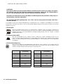
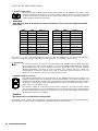
2.8 Power on delay
The ON DELAY switch at the amplifier rear panel allows selecting the power on delay time.
Following table shows possible switch settings and corresponding delay times.
CAUTION:
Blocking/closing the power amp’s ventilation louvers is not permissible. Without sufficient
cooling/ventilation, the power amplifier may automatically enter protect mode. Keep ventilati-
on louvers free from dust to ensure unhindered airflow.
Do not use the power amplifier near heat sources, like heater blowers, stoves or any other heat
radiating devices.
To ensure trouble-free operation, make certain that the maximum allowable ambient tempera-
ture of +40°C is not exceeded.
ON DELAY Delay time
(in s)
ON DELAY Delay time
(in s)
0 0.52 8 1.05
1 0.59 9 1.15
2 0.63 A 1.25
3 0.69 B 1.40
4 0.75 C 1.49
5 0.84 D 1.55
6 0.90 E 1.61
7 0.95 F 1.69

CONTRACTOR PRECISION SERIES
10 Owner‘s Manual
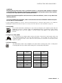
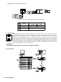
2.9 Selecting the Mode Of Operation and Audio Output Cabeling
The MODE switch on the power amp‘s rear panel defines how the audio inputs handle the input signals. Possible settings are
DUAL, PARALLEL or BRIDGED.
DUAL
In DUAL mode, the two channels of the power amplifier work independent from each other. This mode
of operation is being used for all 2-channel applications, like stereo operation. Using the input level
controls on the power amp’s rear panel allows independently adjusting the channels’ amplification.
PARALLEL
In PARALLEL mode, the inputs of channel 1 and channel 2 are directly electrically linked. The audio
signal has to be applied to the input connectors of channel 1. Using the input level controls to
independently control the amplification of the two channels is still possible because only the channels’
inputs are linked. PARALLEL operation is the mode of choice, whenever the same input signal drives
multiple power amp channels of a large system installation.
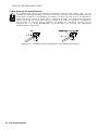
See illustration right for connecting speakers in DUAL or PARALLEL
mode. The correct connection is also indicated at the amplifiers rear
panel.
BRIDGED
In BRIDGED mode both amp channels work in push-pull operation to provide doubled output voltage.
The audio signal has to be applied to the input connectors of channel 1, amplification is set via input
level control of channel 1 only.
Setting the MODE switch on the power amp‘s rear panel to BRIDGED lets the power
amplifier run in bridged mode operation and speaker connection has to be
established using pins 1+ und 2-, see illustration right. The correct connection is also
indicated at the amplifiers rear panel.
CAUTION:
In PARALLEL mode, the input signal has to be fed to input channel 1 only.
CAUTION:
In BRIDGED mode, the input signal has to be fed to input channel 1 only. Amplification is set
via input level control of channel 1 only.
In BRIDGED mode operation, it is not allowable for the load connected to fall below a value of
4 ohms. Extremely high voltages can be present at the output. The connected speaker sy-
stems must be able to handle such voltages. Make sure to completely read and fully observe
power rating specifications of the speaker systems to be used and to check them against the
output power capacity of the power amp.

CONTRACTOR PRECISION SERIES
Owner‘s Manual 11
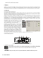
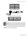
2.10 Audio Input Cabeling
Inputs are electronically balanced. Whenever possible, using balanced audio signal feeds at the input of the power
amplifier is always preferred. Unbalanced connections should only be used if the cables are very short and no
interfering signals are to be expected in the vicinity of the power amplifier. In this case, bridging the screen
(shielding) and the pin of the inverting input inside of the connector is mandatory. Otherwise, a 6 dB drop in level
could result. Please also see following illustration. Due to their immunity against external interference sources,
such as dimmers, mains connections, HF-control lines, etc., using balanced cabling and connections is always
preferable.
Illustration 2.1: Balanced / unbalanced connection of input

CONTRACTOR PRECISION SERIES
12 Owner‘s Manual
3 Operation
3.1 Volume Control
In DUAL and PARALLEL mode, the level controls LEVEL on the power amp’s rear panel are used to control
the amplification of the corresponding channel. Turning the control to the right increases and turning it to the
left decreases the volume. In BRIDGED mode operation, the output volume of the power amp is only
controlled by the CH 1 level control. Any changes in the setting of the CH 2 level control are ignored.
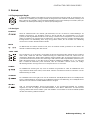
3.2 Indications
PROTECT
The PROTECT LED lights indicating that one of the internal protection circuits against thermal overload,
short-circuit, Back-EMF, HF-occurrence at the output, etc., has been activated. In that case, the output
relays separate the power amps from the load connected to prevent the connected loudspeaker systems
and the power amplifiers as well from being damaged. Whatever caused the fault – e.g. a short-circuited
speaker cable – needs to be remedied. In case of thermal overload you have to wait until the power
amplifier automatically regains normal operation.
MUTE
The MUTE LED lights red whenever the power amp’s output signal is being muted, which happens when
manually muting the output signal via IRIS-Net™.
-30dB...LIMIT
Level indication is realized via vertical LED chains on the power amp’s front panel that individually indicate
the actual levels of each channel at -30dB, -10dB and -3dB below full modulation. The LIMIT LED lights as
soon as the integrated dynamic audio limiter is activated and the power amplifier is driven at the clipping
limit or generally at its maximum capacity. Short-term blinking is not a problem, because the internal limiter
controls input levels of up to +21 dBu down to a THD of approximately 1 %. If, on the other hand, the LIMIT
LED light constantly, reducing the volume is recommended to prevent the loudspeaker systems connected
from being damaged by probable overload.
POWER
The POWER LED lights green when the power amplifier is on. If the POWER-LED does not light, despite
the fact that the amplifier has been switched on, this indicates that the power amp is not connected to the
mains or the primary fuse has blown.
STANDBY
The STANDBY-LED lights yellow when the power amp is in standby mode. Standby mode reduces the
amp’s power consumption to an absolute minimum. Activating the standby mode is possible via IRISNet™
or the POWER REMOTE port at the amp‘s rear panel.
IRIS-Net
The IRIS-Net-LED lights blue if an IRIS-Net™-compatible remote control module has been installed in the
power amp’s extension slot and successful data communication has been established. The IRIS-Net LED
blink slowly whenever the “Find” function in IRIS-Net™ is being used to locate a power amplifier in the rack.

CONTRACTOR PRECISION SERIES
Owner‘s Manual 13
3.3 Standby Mode (POWER REMOTE)
POWER REMOTE provides a simple way to remotely power-on/off the power amplifier. The POWER
REMOTE function is only useful for appliances not employing a Remote Control Modul. Controlling CPS
amplifiers with Remote Control Module installed per POWER REMOTE is not recommended.
Leaving the pins of POWER REMOTE socket open the appliance power is switched on. When connecting
the pins the applicance enters standby mode.
3.4 Fan Cooling
The power amplifier has two fans. The fans are switched in three performance-optimized levels, i.e. they are not running
permanently but the speed of the fans is controlled depending on the temperature. That in return ensures very silent running
during idle state.
The temperatures of the power amps‘s channels are registered and monitored individually.

CONTRACTOR PRECISION SERIES
14 Owner‘s Manual
4 Options
Installing one of the optionally available extension modules in the extension slot on the rear panel lets you expand the power
amp’s functional range. As an example, the following paragraphs describe the RCM-810 Remote Control Module. Please
read and follow the instructions provided in the documentation that you have received together with each extension module.
4.1 RCM-810
System Description and Features
The RCM-810 Remote Control Module is a digital controller module for live sound reinforcement, PA and fixed installation
applications. Installing the RCM-810 turns a conventional amp into a remote amplifier, which, at any time, provides complete
overview of the overall system status and control of all system parameters.
RCM-810 modules allow the integration of amplifiers into a remote control network with up to 250 units. This offers the
possibility to control and monitor an entire PA system from one or more PCs using the IRIS-Net - Intelligent Remote &
Integrated Supervision - software package. All operational states, e.g. power-on status, temperature, activation of protections,
load impedance, etc., are centrally registered and displayed in IRIS-Net. This provides the possibility to react and to
selectively intervene even before critical operational states arise. Programming an automatic reaction, when specific
thresholds are being exceeded or fallen below, is also possible.
All parameters, like power on/off, muting, etc. can be
controlled in real-time and stored in the amplifier. In the
event of network failure or loss of power, all settings stay
intact, independent of the control by the network.
Furthermore, the RCM-810 provides a control port with
freely programmable control inputs and control outputs.
Control inputs (GPI's) allow the connection of switches.
IRIS-Net offers the possibility to program a variety of logic
functions for the inputs. Control outputs (GPO's) allow the
connection of external components, which, for example, are
used to signal specific states to peripheral equipment.
Consequently, an amplifier with a RCM-810 module
installed corresponds to highest safety requirements. For
further details about configuration, control and monitoring of
amps with installed RCM-810 modules, please refer to the
documentation of the IRIS-Net. The latest version of IRIS-Net is available at www.electrovoice.com.
Controls and Connections
1 ADDRESS Selector Switch
The two address selector switches are for setting the network address of the RCM-810. CAN networks
support addresses in the range of 01 to 250 (FA hex). Addressing has to be carried out in the hexadecimal
number system. The LOW selector switch sets the lower digit, while HIGH sets the higher digit.
Illustration 4.1: Controls and Connections of the RCM-810
CAUTION:
Each address may exist only once in a system. Otherwise, network conflicts may arise.

CONTRACTOR PRECISION SERIES
Owner‘s Manual 15
Address 0 (00 hex, delivery status) disables remote communication between the RCM-810 and the bus. The module does not
appear in the system, even though it is physically connected to the CAN-bus.
2 STATUS LED
The STATUS-LED is for monitoring the communication on the CAN bus. The LED blinks rhythmically every 3
seconds, when the module’s address is set to “00“, which means that it is disconnected from the CAN bus
and software control. The LED blinks rhythmically in intervals of one second, when an address in the range of
01 to 250 has been assigned to the module and there has not yet been any activity on the CAN bus. As soon
as communication on the CAN bus is recognized, the LED lights for at least 100 ms, when the power
amplifier sends data on the CAN bus.
3 REMOTE CAN BUS Connection
The RCM-810 module provides two RJ-45 sockets for connecting to the REMOTE CAN BUS. These sockets
are connected in parallel and serve as inputs as well as for daisy-chaining the devices on the remote
network. Cabling in a rack system can be established using commercially available RJ-45 network cables.
However, CAN guidelines have to be observed for longer cable lengths. Both ends of the CAN-bus must be
terminated using 120 Ω terminating plugs.
The CAN bus allows using different data rates, whereas the data rate is inversely proportional to the bus
length. For smaller network setups, data rates can be as high as 500 kbit/s. For broader networks, reducing
the data rate becomes necessary (down to the minimum data rate of 10 kbit/s).
The following table illustrates the relation between data rate and bus length or network size. The use of CAN repeaters is
strongly recommended for busses that exceed 1000 meters in length.
HIGH LOW Address HIGH LOW Address
0 0 Stand-alone 8 0...F 128...143
0 1...F 1...15 9 0...F 144...159
1 0...F 16...31 A 0...F 160...175
2 0...F 32...47 B 0...F 176...191
3 0...F 48...63 C 0...F 192...207
4 0...F 64...79 D 0...F 208...223
5 0...F 80...95 E 0...F 224...239
6 0...F 96...111 F 0...A 240...250
7 0...F 112...127 F B...F reserved
Table 4.1: CAN addresses
NOTE:
The data rate of the CAN bus is preset to 10 kbit/s.
Transfer rate (in kbit/s) Bus length (in m)
500 100
250 250
125 500
62,5 1000
20 2500
10 5000
Table 4.2: Transfer rate and bus length

CONTRACTOR PRECISION SERIES
16 Owner‘s Manual
4 CONTROL PORT
The CONTROL PORT of the RCM-810 provides two control inputs, two control outputs and reference
connections for +5V and ground. The control inputs are configurable via IRIS-Net™. They can be used for
example for switching between power on / standby modes. The two control contacts IN1 and IN2 are
internally connected via pull-up resistors and carry +5V (open). The control inputs can be activated using
external switches, pushbuttons or relays to connect them to ground potential (pin 3). The two control outputs
OUT1 and OUT2 are open collector outputs, which are highly resistive in the non-active state (off). In active
state (on) the outputs are connected to ground. The control outputs are configurable via IRIS-Net™ and are
used to signal internal states. LEDs, indicators or relays can be driven directly. The +5V reference connector
provides voltage supply for connected components.
System Example
Illustration 4.2: Pin-assignment of CAN jack and CAN plug
Pin Name
Colour
T568A T568B
2 CAN_GND Green Orange
4CAN_H(+) Blue
5 CAN_L (-) Blue striped
Table 4.3: Overview CAN plug
CAUTION:
The maximally allowable current at the +5V output is 200 mA.

CONTRACTOR PRECISION SERIES
Owner‘s Manual 17
Page is loading ...
Page is loading ...
Page is loading ...
Page is loading ...
Page is loading ...
Page is loading ...
Page is loading ...
Page is loading ...
Page is loading ...
Page is loading ...
Page is loading ...
Page is loading ...

CONTRACTOR PRECISION SERIES
30 Owner‘s Manual / Bedienungsanleitung
Specifications/Technische Daten
Amplifier at rated conditions, both channels driven, 8 Ω load, unless otherwise specified.
Depending on the ambient temperature, the unit might not operate continously at 2 Ω load in Dual Mode or 4 Ω in Bridged Mode.
In addition input power exceeds 1.1 times rated power consumption with 2 Ω load in Dual Mode or 4 Ω load in Bridged Mode
CPS2.4 CPS2.6 CPS2.9 CPS2.12
Load Impedance 2 Ω 4 Ω 8 Ω 2 Ω 4 Ω 8 Ω 2 Ω 4 Ω 8 Ω 2 Ω 4 Ω 8 Ω
Maximum Midband Output Power
THD = 1%, 1 kHz, Dual Channel
650 W 450 W 270 W 900 W 600 W 380 W 1250 W 900 W 550 W 1800 W 1200 W 750 W
Rated Output Power
THD < 0.1%, 20 Hz...20 kHz
- 400 W 200 W - 500 W 250 W - 800 W 400 W - 1100 W 550 W
Maximum Single Channel Output Power
Dynamic-Headroom, IHF-A
1150 W 660 W 350 W 1700 W 950 W 480 W 2450 W 1400 W 700 W 3400 W 1800 W 950 W
Maximum Single Channel Output Power
Continuous, 1 kHz
850 W 540 W 310 W 1200 W 750 W 420 W 1700 W 1100 W 630 W 2400 W 1500 W 850 W
Maximum Bridged Output Power
THD = 1%, 1 kHz
- 1300 W 900 W - 1800 W 1200 W - 2800 W 1800 W - 3600 W 2400 W
Maximum RMS Voltage Swing
THD = 1%, 1 kHz
55.3 V 65.1 V 78.8 V 90.6 V
Power Bandwidth
THD = 1%, ref. 1 kHz, half power @ 4 Ω
< 10 Hz...30 kHz
Voltage Gain, ref. 1 kHz 32.0 dB
Input Sensitivity
rated power @ 8 Ω, 1 kHz
+2.2 dBu (1.0 V
rms
) +3.1 dBu (1.11 V
rms
) +5.1 dBu (1.39 V
rms
) +6.6 dBu (1.66 V
rms
)
THD at rated output power
MBW = 80 kHz, 1 kHz
< 0.03%
IMD-SMPTE, 60 Hz, 7 kHz < 0.1%
DIM30, 3.15 kHz, 15 kHz < 0.05%
Maximum Input Level +21 dBu (8.69 V
rms
)
Crosstalk
ref. 1 kHz, at rated output power
< -80 dB
Frequency Response, ref. 1 kHz 10 Hz...40 kHz (±1 dB)
Input Impedance, active balanced 20 kΩ
Damping Factor, 1 kHz > 300
Slew Rate 25 V/μs 26 V/μs 27 V/μs 30 V/μs
Signal to Noise Ratio Amplifier
A-weighted
> 106 dB > 107 dB > 109 dB > 110 dB
Output Noise, A-weighted < -71 dBu
Output Stage Topology Class AB Class H
Power Requirements 240 V, 230 V, 120 V or 100 V; 50 Hz...60 Hz (factory configured)
Power Consumption
1/8 maximum output power @ 4 Ω
550 W 700 W 700 W 850 W
Mains Fuse 240 V / 230 V: T10AH;
120 V / 100 V: T20AH
240 V / 230 V: T12AH;
120 V / 100 V: T25AH
240 V / 230 V: T15AH;
120 V / 100 V: T25AH
240 V / 230 V: T15AH;
120 V / 100 V: T30AH
Protection Audio limiters, High temperature, DC, HF, Back-EMF, Peak current limiters, Inrush current limiters, Turn-
on delay
Cooling Front-to-rear, 3-stage-fans
Ambient Temperatur Limits +5 °C...+40 °C (40 °F...105 °F)
Safety Class I
Dimensions (W x H x D), mm 483 x 88.1 x 421.5
Weight 12.6 kg (27.8 lbs) 14.8 kg (32.6 lbs) 16.3 kg (35.9 lbs) 17.7 kg (39.0 lbs)
Signal Processing Lo-Cut 50 Hz / 18 dB, switchable
Optional 2-Way crossover, internal filter card, 24 dB, LR
500 Hz (NRS 90250), 800 Hz (NRS 90251)

CONTRACTOR PRECISION SERIES
Owner‘s Manual / Bedienungsanleitung 31
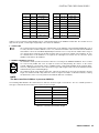
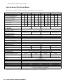
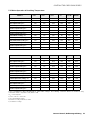
5.1 Mains Operation & Resulting Temperature
Power consumption is direct proportional for other mains voltages. The following conversion factors are meant for easy
conversion: 100V = 2.3; 120V = 1.9; 240V = 0.96
1) P
d
= Power Dissipation
2) 1 BTU = 1055.06 J = 1055.06 Ws
3) Sine Signal Modulation (1 kHz)
4) Pink Noise according to EN60065 / 7. Edition
5) 10% Mains Over Voltage
CPS2.4
U
mains
in V I
mains
in A P
mains
in W P
out
in W
P
d
in W
1
BTU/hr
2
Idle
230 0.3 38 0 38 130
Max. Output Power @ 8 Ω
3
230 4.9 800 540 260 887
Max. Output Power @ 4 Ω
3
230 8.0 1450 900 550 1877
1/3 Max. Output Power @ 4 Ω
3
230 5.1 900 300 600 2047
1/8 Max. Output Power @ 4 Ω
3
230 3.4 550 112.5 437.5 1493
1/8 Max. Output Power @ 4 Ω
4
230 3.0 470 112.5 357.5 1220
1/8 Max. Output Power @ 4 Ω
4 5
253 3.2 560 135 425 1450
Normal Mode (-10 dB) @ 4 Ω
3
230 3.0 450 80 370 1262
Rated Output Power (0 dB) @ 4 Ω
3
230 7.6 1380 800 580 1979
Alert (Alarm) Mode (-3 dB) @ 4 Ω
3
230 5.7 1000 400 600 2047
Max. Output Power @ 2 Ω
3
230 12.1 2250 1300 950 3242
1/8 Max. Output Power @ 2 Ω
3
230 5.2 900 162.5 737.5 2516
1/8 Max. Output Power @ 2 Ω
4
230 4.8 750 162.5 587.5 2005
CPS2.6
U
mains
in V I
mains
in A P
mains
in W P
out
in W
P
d
in W
1
BTU/hr
2
Idle
230 0.4 46 0 46 157
Max. Output Power @ 8 Ω
3
230 6.7 1110 760 350 1194
Max. Output Power @ 4 Ω
3
230 10.8 1970 1200 770 2627
1/3 Max. Output Power @ 4 Ω
3
230 6.9 1150 400 750 2559
1/8 Max. Output Power @ 4 Ω
3
230 4.6 740 150 590 2013
1/8 Max. Output Power @ 4 Ω
4
230 4.0 630 150 480 1638
1/8 Max. Output Power @ 4 Ω
4 5
253 4.5 760 190 570 1945
Normal Mode (-10 dB) @ 4 Ω
3
230 3.9 610 100 510 1740
Rated Output Power (0 dB) @ 4 Ω
3
230 10.0 1800 1000 800 2730
Alert (Alarm) Mode (-3 dB) @ 4 Ω
3
230 7.5 1320 500 820 2798
Max. Output Power @ 2 Ω
3
230 16.6 3260 1800 1460 4982
1/8 Max. Output Power @ 2 Ω
3
230 7.1 1160 225 935 3190
1/8 Max. Output Power @ 2 Ω
4
230 6.2 1040 225 815 2781

CONTRACTOR PRECISION SERIES
32 Owner‘s Manual / Bedienungsanleitung
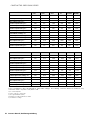
Power consumption is direct proportional for other mains voltages. The following conversion factors are meant for easy
conversion: 100V = 2.3; 120V = 1.9; 240V = 0.96
1) P
d
= Power Dissipation
2) 1 BTU = 1055.06 J = 1055.06 Ws
3) Sine Signal Modulation (1 kHz)
4) Pink Noise according to EN60065 / 7. Edition
5) 10% Mains Over Voltage
CPS2.9
U
mains
in V I
mains
in A P
mains
in W P
out
in W
P
d
in W
1
BTU/hr
2
Idle
230 0.4 46 0 46 157
Max. Output Power @ 8 Ω
3
230 9.4 1740 1100 640 2184
Max. Output Power @ 4 Ω
3
230 15.3 2810 1800 1010 3446
1/3 Max. Output Power @ 4 Ω
3
230 8.7 1450 600 850 2900
1/8 Max. Output Power @ 4 Ω
3
230 3.6 560 225 335 1143
1/8 Max. Output Power @ 4 Ω
4
230 3.6 540 225 315 1075
1/8 Max. Output Power @ 4 Ω
4 5
253 4.1 690 275 415 1416
Normal Mode (-10 dB) @ 4 Ω
3
230 3.2 460 160 300 1024
Rated Output Power (0 dB) @ 4 Ω
3
230 14.4 2640 1600 1040 3549
Alert (Alarm) Mode (-3 dB) @ 4 Ω
3
230 10.2 1770 800 970 3310
Max. Output Power @ 2 Ω
3
230 21.6 4090 2800 1290 4402
1/8 Max. Output Power @ 2 Ω
3
230 5.1 850 350 500 1706
1/8 Max. Output Power @ 2 Ω
4
230 5.0 810 350 460 1570
CPS2.12
U
mains
in V I
mains
in A P
mains
in W P
out
in W
P
d
in W
1
BTU/hr
2
Idle
230 0.5 57 0 57 194
Max. Output Power @ 8 Ω
3
230 12.2 2100 1500 600 2047
Max. Output Power @ 4 Ω
3
230 19.7 3620 2400 1220 4163
1/3 Max. Output Power @ 4 Ω
3
230 11.2 1900 800 1100 3753
1/8 Max. Output Power @ 4 Ω
3
230 4.7 720 300 420 1433
1/8 Max. Output Power @ 4 Ω
4
230 4.7 705 300 405 1382
1/8 Max. Output Power @ 4 Ω
4 5
253 5.3 880 375 505 1723
Normal Mode (-10 dB) @ 4 Ω
3
230 4.1 625 220 405 1382
Rated Output Power (0 dB) @ 4 Ω
3
230 18.9 3340 2200 1140 3890
Alert (Alarm) Mode (-3 dB) @ 4 Ω
3
230 13.4 2330 1100 1230 4197
Max. Output Power @ 2 Ω
3
230 27.5 5165 3600 1565 5340
1/8 Max. Output Power @ 2 Ω
3
230 10.5 1810 450 1360 4640
1/8 Max. Output Power @ 2 Ω
4
230 10.2 1730 450 1280 4368
Page is loading ...
Page is loading ...
Page is loading ...

Subject to change withou prior notice. V3 1/16/09 / F01U076727
AMERICAS EUROPE, AFRICA & MIDDLE-EAST ASIA & PACIFIC RIM
Bosch Security Systems, Inc.
12000 Portland Ave South
Burnsville, MN 55337, USA
USA-Phone:1-800-392-3497
Fax: 1-800-955-6831
Canada-Phone: 1-866-505-5551
Fax:1-866-336-8467
Latin America-Phone: 1-952-887-5532
Fax: 1-952-736-4212
Bosch Sicherheitssysteme GmbH
Robert-Koch-Straße 100
D-85521 Ottobrunn, Germany
Contact & Visitor Address
EVI Audio GmbH
Hirschberger Ring 45
D-94315 Straubing, Germany
Phone: +49 9421 706-0
Fax: +49 9421 706-265
Telex Pte. Ltd.
3015A Ubi Road 1
05-10 Kampong Ubi
Industrial Estate
Singapore 408705
Phone: +65 6746-8760
Fax: +65 6746-1206
-
 1
1
-
 2
2
-
 3
3
-
 4
4
-
 5
5
-
 6
6
-
 7
7
-
 8
8
-
 9
9
-
 10
10
-
 11
11
-
 12
12
-
 13
13
-
 14
14
-
 15
15
-
 16
16
-
 17
17
-
 18
18
-
 19
19
-
 20
20
-
 21
21
-
 22
22
-
 23
23
-
 24
24
-
 25
25
-
 26
26
-
 27
27
-
 28
28
-
 29
29
-
 30
30
-
 31
31
-
 32
32
-
 33
33
-
 34
34
-
 35
35
-
 36
36


Electro-Voice CPS2.4 User manual
- Category
- Supplementary music equipment
- Type
- User manual
Ask a question and I''ll find the answer in the document
Finding information in a document is now easier with AI
in other languages
Related papers
-
Electro-Voice Contractor Precision CPS4 Owner's manual
-
-
-
-
Electro-Voice CP-Series Power Amps CP1800 Owner's manual
-
-
-
-
-
Other documents
-
DYNACORD Power Amplifier DSA 8209 User manual
-
Renkforce MP-8000 Owner's manual
-
Dynacord SL 2400 Owner's manual
-
-
Omnitronic E-900 User manual
-
DYNACORD PowerMate 600 Owner's manual
-
-
IMG Stage Line STA-1800 Owner's manual
-
Stageline STA-250 User manual
-