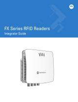
Zebra RFID User guide

Type
User guide
Zebra RFID –
EtherNet/IP
Sample Application
MN-003923-01EN
User Guide
2
ZEBRA and the stylized Zebra head are trademarks of Zebra Technologies Corporation, registered in
many jurisdictions worldwide. All other trademarks are the property of their respective owners.
© 2020 Zebra Technologies Corporation and/or its affiliates. All rights reserved.
Information in this document is subject to change without notice. The software described in this document
is furnished under a license agreement or nondisclosure agreement. The software may be used or copied
only in accordance with the terms of those agreements.
For further information regarding legal and proprietary statements, please go to:
SOFTWARE:www.zebra.com/linkoslegal
COPYRIGHTS:www.zebra.com/copyright
WARRANTY:www.zebra.com/warranty
END USER LICENSE AGREEMENT: www.zebra.com/eula
Terms of Use
Proprietary Statement
This manual contains proprietary information of Zebra Technologies Corporation and its subsidiaries
(“Zebra Technologies”). It is intended solely for the information and use of parties operating and
maintaining the equipment described herein. Such proprietary information may not be used, reproduced,
or disclosed to any other parties for any other purpose without the express, written permission of Zebra
Technologies.
Product Improvements
Continuous improvement of products is a policy of Zebra Technologies. All specifications and designs are
subject to change without notice.
Liability Disclaimer
Zebra Technologies takes steps to ensure that its published Engineering specifications and manuals are
correct; however, errors do occur. Zebra Technologies reserves the right to correct any such errors and
disclaims liability resulting therefrom.
Limitation of Liability
In no event shall Zebra Technologies or anyone else involved in the creation, production, or delivery of the
accompanying product (including hardware and software) be liable for any damages whatsoever
(including, without limitation, consequential damages including loss of business profits, business
interruption, or loss of business information) arising out of the use of, the results of use of, or inability to
use such product, even if Zebra Technologies has been advised of the possibility of such damages. Some
jurisdictions do not allow the exclusion or limitation of incidental or consequential damages, so the above
limitation or exclusion may not apply to you.
Revision History
Change Date Description
MN-003923-01EN Rev. A April 2020 Initial Release
3
Contents
List of Figures..................................................................................................................................... 5
List of Tables....................................................................................................................................... 8
About This Guide................................................................................................................................ 9
Introduction ...................................................................................................................... 9
Chapter Descriptions........................................................................................................ 9
Related Documents and Software ................................................................................... 9
Notational Conventions .................................................................................................. 10
Getting Started.................................................................................................................................. 11
Introduction .................................................................................................................... 11
Requirements................................................................................................................. 11
Hardware Requirements......................................................................................... 11
Software Requirements .......................................................................................... 11
Setting Up the FX9600 Reader with EtherNet/IP Application ........................................ 12
Update the Reader Software .................................................................................. 12
Install EtherNet/IP License ..................................................................................... 12
Install and Run the EtherNet/IP Application ........................................................... 13
Setting Up Sample App with Studio 5000 Logix Designer and PLC Controller.......................... 15
Installing Studio 5000 Logix Designer............................................................................ 15
Installing Zebra RFID AOP Extension............................................................................ 15
Using RFID-EIP Sample Application.............................................................................. 15
Using Non-compatible Versions of Studio 5000 Logix Designer and PLC ............. 16
Importing Rungs............................................................................................... 21
Configuring the Application ............................................................................................ 22
Setting the Reader IP With the Module .................................................................. 22
Configure For the Appropriate Controller ............................................................... 23
Contents
4
Updating the Configuration for MSG Instructions ................................................... 24
Loading the Project to the PLC Controller...................................................................... 25
Configure Driver for EtherNet/IP and Find Controller using RSLinx....................... 25
Set the Controller Path in Project ........................................................................... 27
Load Project to PLC Controller............................................................................... 28
RFID Configuration and Operations Using the EtherNet/IP (EIP) Sample App........................... 32
Reading Reader Capabilities ......................................................................................... 32
Customize Configuration for RFID Operation ................................................................ 34
Reader Profile......................................................................................................... 34
Changing the Active Profile in the Reader ....................................................... 38
Antenna Configuration............................................................................................ 38
Configuring Pre-Filter ............................................................................................. 40
Configuring Access/Post-Filter ............................................................................... 43
Trigger Configuration.............................................................................................. 44
GPIO Configuration ................................................................................................ 45
Reading Event Report ............................................................................................ 46
Performing Inventory...................................................................................................... 47
Start Inventory Operation ....................................................................................... 48
Read Inventory Data............................................................................................... 49
Stop Inventory Operation........................................................................................ 49
Performing Access Operation ........................................................................................ 50
Access Read Operation.......................................................................................... 51
Access Write Operation.......................................................................................... 51
Access Response Data .......................................................................................... 52
Error Codes and Troubleshooting .................................................................................................. 53
Error Codes....................................................................................................................53
EtherNet/IP Stack Error .......................................................................................... 53
RFID Operation Specific Error................................................................................ 55
Troubleshooting ............................................................................................................. 57
Unable to Load Sample Application ....................................................................... 57
Setting Proper Requested Packet Interval (RPI) .................................................... 57
I/O Not Responding Status..................................................................................... 58
Application EtherNet/IP Adapter Application Not Running............................... 58
Reader IP Not Configured/Reachable.............................................................. 58
Communication Path Not Set Properly In MSG Instructions............................ 58
Unable to Perform Inventory or Access Operation........................................... 59
Response Data format ..................................................................................... 59
5
List of Figures
Figure 1: Reader Administration Console ..................................................................... 12
Figure 2: License Manager ........................................................................................... 13
Figure 3: User Application Page ................................................................................... 13
Figure 4: User Application Page - Successful Install .................................................... 14
Figure 5: Create a New Project ..................................................................................... 16
Figure 6: New Project Defaults ..................................................................................... 16
Figure 7: New Empty Project ........................................................................................ 17
Figure 8: Controller Properties ...................................................................................... 17
Figure 9: Change Ethernet/IP Mode ............................................................................. 18
Figure 10: Linear IP Mode ............................................................................................ 18
Figure 11: Module Type ................................................................................................ 19
Figure 12: New Module ................................................................................................. 19
Figure 13: Module Definition ......................................................................................... 20
Figure 14: Newly Added RFID Module .......................................................................... 20
Figure 15: MainProgram - MainRoutine ........................................................................ 21
Figure 16: Import Rungs ............................................................................................... 21
Figure 17: Imported Rungs Window .............................................................................. 22
Figure 18: Module Properties ........................................................................................ 23
Figure 19: Change Controller ........................................................................................ 23
Figure 20: Configuration Dialogue ................................................................................ 24
Figure 21: Communication Tab ..................................................................................... 24
Figure 22: RSLinx Classic Window ............................................................................... 25
Figure 23: Configure Drivers ......................................................................................... 26
Figure 24: Driver Configuration ..................................................................................... 26
Figure 25: RSWho - 1 Dialogue .................................................................................... 27
List of Figures
6
Figure 26: Who Active Dialogue .................................................................................... 28
Figure 27: Project Path ................................................................................................. 28
Figure 28: COMMUNICATIONS > Download ............................................................... 29
Figure 29: Download Confirmation ................................................................................ 29
Figure 30: Download Status .......................................................................................... 30
Figure 31: Set Remote Run .......................................................................................... 30
Figure 32: Green Status Modes .................................................................................... 31
Figure 33: Rung Instructions for Reading Capabilities .................................................. 32
Figure 34: ENABLE.GetReaderCaps flag = TRUE ....................................................... 33
Figure 35: ReaderCaps Data ........................................................................................ 33
Figure 36: Rungs Performing an Operation .................................................................. 35
Figure 37: Specifying the Profile Index Number ........................................................... 35
Figure 38: Controller Tags ............................................................................................ 36
Figure 39: Obtaining the Number of Profiles ................................................................. 36
Figure 40: Number of Available Profiles ........................................................................ 37
Figure 41: Active Profile Instance from Profile List Class ............................................. 37
Figure 42: Active Profile Instance ................................................................................. 38
Figure 43: Get and Set Antenna Configuration ............................................................. 38
Figure 44: Specify Antenna ID ...................................................................................... 39
Figure 45: Antenna Configuration Values ..................................................................... 39
Figure 46: Antenna ID to Modify ................................................................................... 40
Figure 47: Pre-filter Explicit Message ........................................................................... 40
Figure 48: Specify the Filter Index ................................................................................ 41
Figure 49: PreFilterConfig Tag ...................................................................................... 41
Figure 50: Modify the MSG Instruction .......................................................................... 42
Figure 51: Delete a Pre-filter ......................................................................................... 42
Figure 52: AccessPostFilter Operation ......................................................................... 43
Figure 53: AccessPostFilter Tag ................................................................................... 43
Figure 54: Configure Trigger Values ............................................................................. 44
Figure 55: Trigger Values .............................................................................................. 44
Figure 56: GPIO Configuration ...................................................................................... 45
Figure 57: GPIOConfig Tags ......................................................................................... 45
Figure 58: Generate Events .......................................................................................... 46
List of Figures
7
Figure 59: Set Event Type ............................................................................................ 46
Figure 60: Inventory Operation ..................................................................................... 47
Figure 61: Green Enabled Status .................................................................................. 47
Figure 62: Modifying OutputInventoryCommand .......................................................... 48
Figure 63: Reading Inventory Data ............................................................................... 49
Figure 64: Stop Inventory Operation ............................................................................. 49
Figure 65: Access Operation/Read Access Data .......................................................... 50
Figure 66: Access Operation ......................................................................................... 50
Figure 67: Access Read Operation ............................................................................... 51
Figure 68: Access Write Operation ............................................................................... 52
Figure 69: Access Response Data ................................................................................ 52
Figure 70: Module Properties Window .......................................................................... 58
Figure 71: Module Properties Window .......................................................................... 59
Figure 72: Style Window ............................................................................................... 60
8
List of Tables
Table 1: Rung Instructions ............................................................................................ 32
Table 2: Profile List Explicit Message Data Model ........................................................ 34
Table 3: OutputInventoryCommand Field Descriptions ................................................ 48
Table 4: EtherNet/IP Stack Errors ................................................................................. 53
Table 5: RFID Operation Specific Errors ....................................................................... 55
9
About This Guide
Introduction
This guide describes how to use the EtherNet/IP (EIP) sample application with the FX Series RFID reader
using Studio 5000 Logix Designer.
IMPORTANT: If you have a problem with your equipment, contact Zebra Global Customer Support for
your region. Contact information is available at: www.zebra.com/support
.
Chapter Descriptions
Topics covered in this guide are as follows:
Getting Started provides the pre-requisites to run the EtherNet/IP application with the RFID reader.
Setting Up Sample App with Studio 5000 Logix Designer and PLC Controller explains how to setup
Studio 5000 Logix Designer with the sample application and how to load the sample application to the
PLC controller.
RFID Configuration and Operations Using the EtherNet/IP (EIP) Sample App explains how to configure
the reader with RFID specific configuration to perform Inventory and Access operations.
Error Codes and Troubleshooting lists the error codes specific to the EtherNet/IP protocol and RFID
operation, and includes information to troubleshoot common issues when running the application.
Related Documents and Software
The following documents provide more information.
FX Series RFID Fixed Reader Integration Guide
FX Series RFID Fixed Reader FX Connect Licensing Management User Guide
RFID Reader Software Interface Control Guide
EtherNet/IP Deliverable
For the latest version of this guide and all guides, go to www.zebra.com/support
.
About This Guide
10
Notational Conventions
The following conventions are used in this document:
•Bold text is used to highlight the following:
Dialog box, window and screen names
Drop-down list and list box names
Check box and radio button names
Icons on a screen
Key names on a keypad
Button names on a screen.
Bullets (•) indicate:
Action items
Lists of alternatives
Lists of required steps that are not necessarily sequential.
Sequential lists (such as those that describe step-by-step procedures) appear as numbered lists.
11
Getting Started
Introduction
This chapter explains the pre-requisites and procedures to install the Studio 5000 Logix Designer; add the
Zebra RFID reader AOP (Add-On Profile) extension to Studio 5000 Logix Designer; and, configure/use the
sample application with custom RFID configurations.
Requirements
This section describes software and hardware requirements and how to use the Zebra FX9600 RFID
reader with an EtherNet/IP industrial protocol.
Hardware Requirements
Zebra FX9600 RFID Reader
PLC compliant with EtherNet/IP
NOTE: The EtherNet/IP stack in the FX9600 RFID reader requires two I/O connections with the PLC and
consumes approximately 6KB of memory for all data.
Software Requirements
FX9600 RFID Reader updated with 3.6.21 build or later
Zebra EtherNet/IP license installed on Reader
Studio 5000 Logix Designer v32.0 or later
AOP installed with Studio 5000 Logix Designer
RSLinx Classic v32 or later
Sample project downloaded from Zebra Support Central
Project Rungs and Data Types from Zebra Support Central
Getting Started
12
Setting Up the FX9600 Reader with EtherNet/IP Application
The FX9600 reader is enabled with the EtherNet/IP stack with the embedded application. The EtherNet/IP
application is available with FX9600 build version 3.6.21, and later, and can be downloaded as an
installable Debian package. See Update the Reader Software for information about updating the FX9600
reader with appropriate version.
EtherNet/IP is a licensed feature and requires the installation of a Zebra EIP license before using the
application with the Zebra FX9600 RFID reader. See Install EtherNet/IP License for information about
obtaining and installing the license.
When the license is successfully installed, the user can run the EIP application through the web console.
See Install and Run the EtherNet/IP Application for information about installing and running the application.
Update the Reader Software
To use the EIP functionality, the FX9600 Reader must run firmware version 3.6.21, or later. Verify the
current running version from the FX9600 Reader web-console shown in Figure 1.
Figure 1 Reader Administration Console
If the reader is running an older software version, upgrade the reader with new version. Download the FX
Series RFID Fixed Reader Integration Guide and follow the instructions in the section Firmware Upgrade.
Download the latest software for the FX9600 Reader at:
www.zebra.com/us/en/support-downloads/software/operating-system/fx9600-series-operating-system.html
.
When the reader runs the appropriate software version, install the EIP license to run the application.
Install EtherNet/IP License
Install the EIP license (for EtherNet/IP) from the FX9600 Reader web-console. Follow the instructions in
the FX Series RFID Fixed Reader FX Connect Licensing Management User Guide to request, obtain, and
install the license for Zebra FX Series readers.
When the license is installed, the licensing information can be viewed from the web-console shown in
Figure 2.
Getting Started
13
Figure 2 License Manager
Install and Run the EtherNet/IP Application
The EIP application can be installed one of two ways:
along with the license by enabling the check-box Install and Run application
or
by installing the application with the web-console as a Debian package.
To install the application as a Debian package:
1. Navigate to the User Application Page and browse for downloaded application Debian package.
Figure 3 User Application Page
2. Click Install. When the application is installed, it is available under Existing Packages in the List of
Installed apps drop-down list.
Getting Started
14
3.
To run the application, click the red START/STOP button The button turns green to show the
application status as running. The user can also choose to AutoStart the application on reader reboot
by selecting the AutoStart check-box.
Figure 4 User Application Page - Successful Install
NOTE: The web-console session logs out upon application start-up. The user must login to the
web-console again to access the reader.
4. When the application starts, PLC Controller connects with it and is ready to perform RFID operations
through the EtherNet/IP protocol.
15
Setting Up Sample App with
Studio 5000 Logix Designer
and PLC Controller
Installing Studio 5000 Logix Designer
If not already installed, the user must install Studio 5000 Logix Designer to use the sample application.
Studio 5000 Logix Designer provides a means to load the program into PLC and to communicate with PLC
to perform operations using sample application. Follow the installation instructions from Rockwell
Automation. A license may be required for Studio 5000.
Download the studio 5000 Logix Designer version from Rockwell Studio at:
www.rockwellautomation.com/global/products/factorytalk/overview.page?pagetitle=Studio-5000-Logix-De
signer&docid=924d2f2060bf9d409286937296a18142.
Installing Zebra RFID AOP Extension
There are custom Add-On Profiles (AOP) extensions which can be used with Studio 5000 Logix Designer.
Install the Zebra RFID AOP as a Studio 5000 extension.
An AOP is used within Studio 5000 Logix Designer to define a specific piece of hardware and how it reacts
within the control system. AOP is the customized extension and it provides the capability to configure the
project for specific hardware with predefined control parameters.
Once AOP is installed, the Zebra RFID module will be available in Studio 5000 Logix Designer. The
designer creates Zebra RFID specific EtherNet/IP assembly objects for input and output assemblies and
creates supporting data structures.
Download the Zebra RFID AOP extension at:
www.zebra.com/us/en/support-downloads/rfid/rfid-readers/fx9600.html
.
Once downloaded, double click the installer and follow on-screen instructions to add the Zebra RFID AOP
extension to Studio 5000 Logix Designer. System may need to restart after installing AOP.
Using RFID-EIP Sample Application
Once Studio 5000 Logix Designer and custom Zebra RFID AOP are installed the user can open the
sample application with Studio 5000 Logix Designer. The sample application is created using Studio 5000
Logix Designer v32.12 and CompactLogix 5380 Controller (Model 5069-L306ER).
IMPORTANT: There are some limitations with Studio 5000 Logix Designer that might require modifications
in the sample application. If Studio 5000 Logix Designer and the PLC versions are not compatible with the
setup, see Using Non-compatible Versions of Studio 5000 Logix Designer and PLC on page 16 for details.
Setting Up Sample App with Studio 5000 Logix Designer and PLC Controller
16
With compatible versions of Studio 5000 Logix Designer and the PLC, the user can open the sample
application with a (dot)ACD extension in Studio 5000 Logix Designer. See Configuring the Application on
page 22 for application configuration.
Using Non-compatible Versions of Studio 5000 Logix Designer and PLC
If Studio 5000 Logix Designer and the PLC versions are not compatible, the user needs to create a new
project to import the Rungs which are available in the sample application package. Follow the steps below
to create a new project and import the Rungs.
1. Start Studio 5000 Logix Designer and choose to create a new project.
2. Choose the appropriate controller and provide name of the project as shown in Figure 5.
Figure 5 Create a New Project
3. Click Next.
Figure 6 New Project Defaults
Setting Up Sample App with Studio 5000 Logix Designer and PLC Controller
17
4.
Leave the default options as is and click Finish. A newemptyprojectgenerates.
5. Configure the controller properties by right clicking on Ethernet Connection from I/O Configuration in
left panel as shown in Figure 7.
Figure 7 New Empty Project
6. The user can edit the controller configuration as per their controller and requirement.
Figure 8 Controller Properties
7. The sample application uses LinearIPmodeforEtherNet/IP.ClickChangeIPMode....
8. IntheNewmode:dropdownbox,changetheIPmodefromDualIPtolinearasshowninFigure 9.
Setting Up Sample App with Studio 5000 Logix Designer and PLC Controller
18
Figure 9 Change Ethernet/IP Mode
9. Click OK in the Change EtherNet/IP mode dialogue.
10. Click OK ion Controller Properties dialogue.
11. The controller mode is changed to Linear IP mode as shown in Figure 10.
Figure 10 Linear IP Mode
12. Add the new RFID module to the project for RFID assembly operation by right clicking Ethernet
Controller under I/O Configuration in the left plane in Figure 10
.
13. Select New Module to open a module selection dialogue with all available modules.
14. Enter FX9600 in the filter text box to display the Zebra specific RFID Reader Module (FX9600) shown
in Figure 11.
Setting Up Sample App with Studio 5000 Logix Designer and PLC Controller
19
Figure 11 Module Type
15. Select the FX9600 module and click Create.
Figure 12 New Module
16. Add the module related information shown in Figure 12.
a. Name: <Name of the module as per your choice>
b. Description: <Module Description> (optional)
c. IP Address: <IP Address of RFID Reader>
d. Theusercanalsochoosethemoduledefinition(twoavailableconfigurations)byclickingChange...
belowModuleDefinition.TheModuleDefinitiondialoguewindowdisplaysandtheusercan
choosetheconnectionfromthedropdownmenu.
Setting Up Sample App with Studio 5000 Logix Designer and PLC Controller
20
Figure 13 Module Definition
Select Inventory Response Extended Size EPC ID, Access Response or Inventory Response
Standard Size EPC ID, Access Response. Both connections support Inventory and Access
operations. The main difference is in the inventory response. The first connection can be used when
the user needs to support TAGs with max 64 Bytes EPC length. The second connection can read up
to 12 Bytes EPC length only, which is the standard EPC ID length. The advantage of using standard
EPC length is that more EPC IDs (more tags) can be reported per each refresh cycle.
17. Click OK. (In this example, Inventory Response Standard Size EPC ID, Access Response was
selected.)
18. Click OK again in the New Module dialogue window.
19. Click on Close to close the module selection dialogue. The new Zebra RFID module is added in the
project.
Figure 14 Newly Added RFID Module
  • Page 1 1
  • Page 2 2
  • Page 3 3
  • Page 4 4
  • Page 5 5
  • Page 6 6
  • Page 7 7
  • Page 8 8
  • Page 9 9
  • Page 10 10
  • Page 11 11
  • Page 12 12
  • Page 13 13
  • Page 14 14
  • Page 15 15
  • Page 16 16
  • Page 17 17
  • Page 18 18
  • Page 19 19
  • Page 20 20
  • Page 21 21
  • Page 22 22
  • Page 23 23
  • Page 24 24
  • Page 25 25
  • Page 26 26
  • Page 27 27
  • Page 28 28
  • Page 29 29
  • Page 30 30
  • Page 31 31
  • Page 32 32
  • Page 33 33
  • Page 34 34
  • Page 35 35
  • Page 36 36
  • Page 37 37
  • Page 38 38
  • Page 39 39
  • Page 40 40
  • Page 41 41
  • Page 42 42
  • Page 43 43
  • Page 44 44
  • Page 45 45
  • Page 46 46
  • Page 47 47
  • Page 48 48
  • Page 49 49
  • Page 50 50
  • Page 51 51
  • Page 52 52
  • Page 53 53
  • Page 54 54
  • Page 55 55
  • Page 56 56
  • Page 57 57
  • Page 58 58
  • Page 59 59
  • Page 60 60
  • Page 61 61

Zebra RFID User guide

Type
User guide

Ask a question and I''ll find the answer in the document

Finding information in a document is now easier with AI