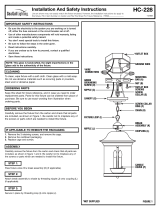
*PARALLEL WIRE (ROUND & SMOOTH) *PARALLEL WIRE (SQUARE & RIDGED)
BLACK WHITE
GROUP A:
CONNECT TO BLACK HOUSE WIRE
GROUP B:
CONNECT TO WHITE HOUSE WIRE
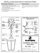
GROUNDING INSTRUCTIONS: The gr
een gr
ounding screw (D) is to
be inserted into the hole with two raised dimples provided on the
mounting bar (A). Wrap the ground wire from the fixture (if supplied)
and the gr
ound wir
e from the outlet box (bar
e metal or green
insulated wir
e) around the green grounding screw (D) on the
mounting bar (A). If uninsulated ground wire is on the mounting bar,
connect the ground wire from the fixture (if supplied) and the outlet
box to it using a small wire connector (not supplied).
NEVER CONNECT GROUND WIRE TO BLACK OR WHITE POWER
SUPPL
Y WIRES.
INSTALLATION (continued) HC-332
STEP 2:
A. Take note of the color of the wire(s) on your fixture. Identify which
group your fixture wire(s) falls into and connect the wires according
t
o the directions below:
STEP 3:
I
nstall glass or polycarbonate diffuser panels (E) in the cage (F)
(if applicable).
Make sure no bare wires can be seen outside wire connectors.
Install lamps.
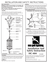
FINAL ASSEMBLY
STEP 5:
STEP 6:
Raise cage (F) over the fixture pan (G) and secure in place with
fixture mounting screws (J).
STEP 7:
A. Take note of the color of the wire(s) on your fixture. Identify which
group your fixture wire(s) falls into and connect the wires according
to the directions below:
*Note: When parallel wire is used, the tracer wire is square shaped or
ridged and less tracer wire is round in shape or smooth
(Seen best when viewed from wire end). To separate wires, grasp the
ends of each wire and pull apart.
B. Take your fixture wire(s) from group A and place evenly against
the black wire from the outlet box.
DO NOT twist wires together
before using wire connectors.
C. Fit a wire connector (not supplied) over the wires and thread the
connector clockwise until you feel a firm resistance.
D. Gently try to remove the wires from the connector, If you can
remove the wires, carefully re-do steps B and C, as above and check
again for a firm connection.
E. Connect the fixture wire from group B to the white wire from the
outlet box in the same manner.
A
fter wires are connected, tuck them carefully inside outlet box and
then raise the fixture pan (G) against ceiling and secure with cap
nut (H).
STEP 4: