
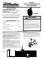
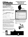
STAR250
TM
WIRELESS
ACCESS CONTROL
RECEIVER
WARNING
CAUTION
WARNING
WARNING
Removable memory modules and RF module are included
in this product. Jumper J2 must remain in the default posi-
tion unless otherwise noted. THERE ARE NO OTHER SER-
VICEABLE PARTS.
TABLE OF CONTENTS
DESCRIPTION
PAGE
Mounting Instructions for STAR250...................1
Programming For STAR250...........................2 & 3
STAR250 Features.............................................4
Electrical Connections for STAR250..................4
SPECIFICATIONS
SUPPLY VOLTAGE: 12-24 VOLTS AC OR DC
OPERATING CURRENT: 250 mA MAXIMUM
OPERATING TEMP RANGE: -40 TO +149F
(-40 TO +65C)
FREQUENCY: 433.92
RELAY CONTACT RATING: 1 AMP @ 24 VOLTS AC OR DC
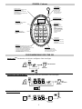
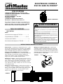
MOUNTING INSTRUCTIONS FOR STAR250
Location: Select a convenient location near your device
to be controlled by the STAR250. For best performance,
the STAR250 should be mounted in Line-Of-Sight with
your intended transmitting location. Avoid mounting the
STAR250 in or on metallic enclosures. If this is
unavoidable, we recommend installing the antenna exten-
sion kit (86LM) for best results. See Remote Antenna
Mounting for proper installation.
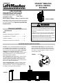
Receiver Mounting: Mount Backplate to desired surface
using M3 hardware (not supplied). Hardware used will
depend on mounting application. (Refer to figure 1 for
Receiver mounting hole locations). Wire electrical connec-
tions to unit. Snap Unit to Back Plate.
Direct Antenna Mounting: Install the supplied antenna
onto the STAR250 antenna connector by screwing the
connector clockwise. Slide the seal boot down to meet
the O-Ring, covering the antenna hardware.
SEAL BOOT
ANTENNA
ANTENNA
CONNECTOR
PATENTS PENDING
FIGURE 1
FIGURE 2
Remote Antenna Mounting: Use the optional 86LM
antenna extension kit to mount the remote antenna as
high and far from metal as possible for best radio range
(See figure 2). Contact LiftMaster customer service to
order the model 86LM.
To prevent possible SERIOUS INJURY or DEATH from electrocution:
• Be sure power is not connected BEFORE installing the receiver.
To prevent possible SERIOUS INJURY or DEATH from a moving gate
or garage door:
• ALWAYS keep remote controls out of reach of children. NEVER per-
mit children to operate, or play with remote control transmitters.
• Activate gate of door ONLY when it can be seen clearly,is proper-
ly adjusted, and there are no obstructions to door travel.
• ALWAYS keep gate or garage door in sight until completely closed.
NEVER permit anyone to cross path of moving gate or door.
1

2
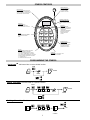
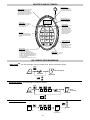
PROGRAMMING THE STAR250
Add
#
PRESS
PRESS
TO EXIT
AUTO
PRESS
Add
#
PRESSENTER LOCATION (1-250)
PRESS
TO EXIT
AUTO
PRESS
2 3 4
PRESS
TO
CONFIRM
ENTER LOCATION (1-250)
END
PRESS
2 3 4
Delete Delete
Rapid Learn
TM
- Add transmitter to next available location.
Adding Transmitter- Add transmitter to a specific location.
Deleting a Transmitter- To delete a user.
1
4
789
0
#
56
23
Add Delete
Block
*
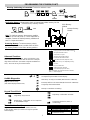
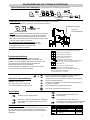
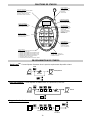
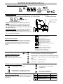
STAR KEY
USED TO ENTER ADVANCED FUNCTIONS:
*,1- LAST TRANSMITTER RECEIVED
*,2- NO. OF UNUSED MEMORY LOCATIONS
*,3- NO. OF OCCUPIED MEMORY LOCATIONS
*,4- NO. OF BLOCKED TRANSMITTER LOCATIONS
*,5- FIRST BLOCKED TRANSMITTER LOCATION
*,7- SOFTWARE VER. #
*,0- AUDIBLE DIAGNOSTICS OFF/ON
POUND KEY
USED AS AN ESC OR EXIT KEY FOR
ALL FUNCTIONS OR MODES.
DELETE KEY
USED TO DELETE A
TRANSMITTER FROM THE
SELECTED MEMORY LOCATION
ANTENNA CONNECTION
FOR CONNECTION TO THE
DIRECT ANTENNA
OR THE ANTENNA EXTENSION
KIT.
POWER INDICATOR
SCROLLING DASHES ON
DIGITAL DISPLAY WHEN
AC OR DC POWER IS
APPLIED TO THE UNIT.
NUMERIC KEYPAD
USED FOR PROGRAMMING
AND QUERYING
TRANSMITTER LOCATIONS.
ALSO USED TO ENTER
ADVANCED FUNCTIONS.
DIGITAL DISPLAY
DISPLAYS TRANSMITTER LOCATION
NUMBERS WHEN PROGRAMMING OR
ACCESS IS GRANTED. ALSO DISPLAYS
USER PROMPTS AND MESSAGES.
BLOCK KEY
USED TO BLOCK THE
RECEIVER FROM GRANTING
ACCESS TO THE SELECTED
TRANSMITTER.
TRANSMITTER REMAINS IN
MEMORY, AND MAY BE
UNBLOCKED IN THE
FUTURE.
ADD KEY
USED TO ENTER TRANSMITTERS
AND ENTER RAPID LEARN
TM
MODE.
STAR250 FEATURES

3
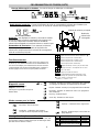
PROGRAMMING THE STAR250 (CON’T)
Advanced Functions
Step 1. For advanced functions, press and hold the (*) key
and a number key at the same time to select the correspon-
ding advanced function. (See table at right for available func-
tions.) Press the ‘#’ key to exit the function.
Audible Diagnostics
Step 1. Activate Transmitter.
Step 2. Listen for beep.
(LED will be displayed when OFF)
Transmitter location Query
Step 1. Enter a transmitter location number (001-250)
to view location status (See table to the right for possible
status displays).
PRESS
TO
CONFIRM
ENTER LOCATION (1-250)
END
(UNBLOCK)
PRESS
2 3 4
Block Block
OR
*
1
*
2
*
3
*
4
*
5
5
*
6
*
7
#
*
0
Memory location of last transmitter received.
# of open transmitter locations.
# of locations occupied.
# of blocked transmitter locations.
First blocked transmitter location.
*
If no transmitters are programmed into the STAR250,
then (---) will be displayed.
*
Next blocked location (Repeat to scroll).
Duplicate memory- See Duplicating memory.
Version #
Press to exit functions.
Audible diagnostics OFF/ON
(LED will be displayed when OFF)
*
6
PRESS SIMULTANEOUSLY
,
END
~6 SECONDS
OPn
Occ
bLc
Out
Transmitter location is empty
Transmitter location is occupied
Transmitter location is blocked
Transmitter location is out of range
no beep
Display Description
Beeper
no beep
no beep
long beep
(not between 1 & 250)
Triple Beep- Confirmation of Delete.
Long Beep- Blocked Tx, Error, or
Out of Range
Double Beep- Transmitter is valid & learned into STAR250
accompanied by transmitter location display.
Slow Beep- Security+ Transmitter (Not learned in STAR250).
Fast Beep- Billion Code Transmitter (Not learned in STAR250).
Long Beep- Blocked transmitter.
No Beep- Transmitter not working.
Single Beep- Key Pressed.
Double Beep- Confirmation of an accepted Tx
or valid Add/Block input.
Keypad Sound
Alerts
Blocking (Unblocking) a Transmitter- To block or unblock a user.
Duplicating Memory- Allows user to back up learned transmitter memory into the
provided backup memory module.
Note- To duplicate memory, plug memory module
into back up slot and press *,6. Once duplication is
complete, remove the backup memory module and
store in a separate location.
Backup Memory
Module
Main Memory
Module
Restoring Memory- To restore memory, simply
place the duplicate memory module from the back-
up memory location in the main memory position.

4
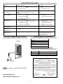
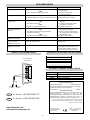
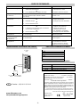
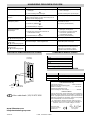
ELECTRICAL CONNECTIONS FOR STAR250
Model 23024E
Transformer
To wall
outlet
RECEIVER
(Bottom)
RELAY
COM
N.O.
CONTACT
12-24V
AC/DC
STAR250 COMPATIBLE TRANSMITTERS
Transmitters
4330E
4332E
4333E
4335E
Keypads
747E
STAR250 OPTIONAL ACCESSORIES
CGI Part Number Description
041A2743X Watertight Box Field Install Kit
86LM Antenna Extension Kit
23024E Transformer 230V/24V/AC
TROUBLESHOOTING GUIDE
Problem Probable Cause(s) Solution
No Display 1. Faulty/intermittent power connections to unit
Or
2. No power to unit
1. Check power connections to
unit
2. Supply power to unit
No Beep when
transmitting
Audible Diagnostics may have been turned OFF
(right-most decimal point will be lit on the
display)
Press "*" and "0" keys at the same
time.
Transmitter does not
activate operator
1. Transmitter not learned into system
Or
2. Transmitter is blocked
Or
3. Transmitter battery is dead
1. Add transmitter to memory
2. Pay your rent
3. Replace transmitter battery
Transmitter won't learn
into memory
1. Memory may be full
Or
2. Transmitter may not be a recognized
Chamberlain transmitter
Or
3. Transmitter battery is dead
1. Delete unused transmitters
from memory
2. Verify transmitter is listed in
compatible transmitters
section
3. Replace transmitter battery
Unit does not function,
[E 1] displayed
Main memory module missing or damaged Replace Main memory module
Duplication function does
not work,
[E 2] displayed
Backup memory module missing or damaged-
If included
Replace Backup memory module
Keypad does not respond,
[E 3] displayed
Keypad has a stuck key Cycle power.
If unit exhibits this condition
again after 2 minutes, contact
Technical Service
Declaration of Conformity
Universal Radio Receiver.....................................Model No.Star250-xxx
are in conformity to the applicable sections of Standards.ETS 300 683,
per the provisions & all amendments of the EU Directives ....1999/5/EC
Declaration of Incorporation
Universal Radio Receiver Model No. Star250-433, when installed and
maintained according to all the Manufacturer’s instructions in combination
with a Gate or Garage Door System, which have also been installed and
maintained according to all the Manufacturer’s instructions, meets the pro-
visions of EU Directive 98/37/EC and all ammendments.
I, the undersigned, hereby declare that the equipment specified
above and any accessory listed in the manual conforms to the
above Directives and Standards.
Chamberlain GmbH
D-66793 Saarwellingen
September 2002
Colin B. Willmott
Chefingenieur
For Service: +(44) 0845-602-4285
GB
www.liftmaster.com
Page is loading ...
Page is loading ...
Page is loading ...
Page is loading ...
Page is loading ...
Page is loading ...
Page is loading ...
Page is loading ...
Page is loading ...
Page is loading ...
Page is loading ...
Page is loading ...
-
 1
1
-
 2
2
-
 3
3
-
 4
4
-
 5
5
-
 6
6
-
 7
7
-
 8
8
-
 9
9
-
 10
10
-
 11
11
-
 12
12
-
 13
13
-
 14
14
-
 15
15
-
 16
16


Chamberlain LiftMaster STAR 250 - 433 MHz Owner's manual
- Type
- Owner's manual
- This manual is also suitable for
Ask a question and I''ll find the answer in the document
Finding information in a document is now easier with AI
in other languages
Related papers
-
Chamberlain LiftMaster SUB324 Owner's manual
-
-
-
-
-
-
-
-
Other documents
-
Merlin E8003 User manual
-
 Seip A-Series Installation guide
-
Fadini Astro 43 MQB Owner's manual
-
 Seip C Series Installation guide
-
Nice BIO Owner's manual
-
LiftMaster LMWEKITU User manual
-
Erone SEL39R433-P4 Use And Installation Manual
-
 BTX 2.4 GHz Programming Manual
-
 Seip Easy SM Owner's manual
-
 Seip M50 Installation guide


