Page is loading ...

Operator stations
User Manual Version 2.00
POLARIS Panel PC 19.1" and Panel PC 15"
Type 17-71V1-....

Wichtiger Hinweis zum Transport und Versand
! Empfindliche Geräte !
Es ist unbedingt erforderlich das Gerät in der Originalverpackung
zu versenden, um Beschädigungen am Gerät zu vermeiden.
Important note concerning transportation and shipping
! Sensitive equipment !
It is absolutely necessary to deliver the equipment in the original
packaging in order to avoid damage occuring with the equipment.
Important : concerne l’expédition et le transport
! Produits fragiles !
Il est important d’expédier le matériel dans l’emballage
d’origine afin d’éviter tout dégât dû au transport.

USER MANUAL
POLARIS
Panel PC 19.1'' / Panel PC 15''
English


User manual
POLARIS Panel PC 19.1'' and Panel PC 15''
Version 2.00 Page 5 of 46
E_BMS790_POLARIS_PanelPC_19+15_Rev1.doc • User manual for POLARIS Panel PC 19.1" and 15" • Revision 1 / Status: January, 3
rd
, 2006 • Technical data subject to change
Contents
1. System description..................................................................................................................................... 7
2. Technical data POLARIS Panel PC...................................................................................................... 10
2.1 Characteristics data Panel PC 19.1'' und Panel PC 15''............................................................. 10
2.2 General data .............................................................................................................................. 10
2.3 Characteristics data Panel PC 19.1''.......................................................................................... 11
2.4 Characteristics data Panel PC 15''............................................................................................. 12
2.5 Characteristics data keyboard.................................................................................................... 13
2.6 Characteristics data mouse, trackball and touchpad.................................................................. 14
2.6.1 Mouse........................................................................................................................................ 14
2.6.2 Trackball .................................................................................................................................... 14
2.6.3 Touchpad................................................................................................................................... 14
3. Terminal assignment................................................................................................................................ 16
3.1 Terminal assignment Ex e.......................................................................................................... 16
3.2 Terminal assignment Ex i........................................................................................................... 17
3.3 Electrical installation .................................................................................................................. 17
3.3.1 EMC notes ................................................................................................................................. 17
3.3.2 Interference suppression............................................................................................................ 18
3.3.3 Shielding .................................................................................................................................... 18
3.3.4 Connection of shielding.............................................................................................................. 19
3.3.5 Examples of how shielding can be connected ........................................................................... 19
3.3.6 Connection of Ethernet cable to POLARIS Panel PCs .............................................................. 20
4. Overview of connection diagram ............................................................................................................ 21
4.1 Possible connection ................................................................................................................... 21
5. Notes on the installation of POLARIS Panel PC .................................................................................... 22
5.1 Safety instructions...................................................................................................................... 22
5.1.1 Safety-relevant notice ................................................................................................................ 22
5.2 Maintenance .............................................................................................................................. 22
5.2.1 Servicing .................................................................................................................................... 22
5.2.2 Inspection .................................................................................................................................. 22
5.3 Installation options ..................................................................................................................... 23
5.3.1 Cable glands / Conduits............................................................................................................. 23
5.4 Mechanical installation............................................................................................................... 24
5.4.1 Recommended enclosure .......................................................................................................... 24
5.4.2 Special installation instructions .................................................................................................. 24
5.4.3 Cover Ex i terminal box.............................................................................................................. 24
5.4.4 General data .............................................................................................................................. 25
5.4.5 Installation guidelines................................................................................................................. 26

User manual
POLARIS Panel PC 19.1'' and Panel PC 15''
Version 2.00 Page 6 of 46
E_BMS790_POLARIS_PanelPC_19+15_Rev1.doc • User manual for POLARIS Panel PC 19.1" and 15" • Revision 1 / Status: January, 3
rd
, 2006 • Technical data subject to change
Contents
6. Connection cables (pin assignment) ...................................................................................................... 27
6.1 RS 422 interface ........................................................................................................................ 27
6.2 RS 485 interface ........................................................................................................................ 28
6.3 PROFIBUS-DP interface............................................................................................................ 29
6.4 Supply module for BCS 302
ex
.................................................................................................... 30
7. Installation additional components......................................................................................................... 31
7.1 Connection of Ex i keyboard to the POLARIS Panel PC............................................................ 31
7.2 Connection of BARTEC USB Ex i memory stick........................................................................ 31
7.3 Connection of USB CD Rom drive............................................................................................. 31
7.4 Connection of USB mouse and USB keyboard.......................................................................... 31
8. Configuration of POLARIS Panel PCs................................................................................................. 32
8.1 Network (Ethernet) setup ........................................................................................................... 32
8.2 Calibration of touch screen ........................................................................................................ 35
8.2.1 Touch screen signs and symbols in notification area................................................................. 36
9. Accessories............................................................................................................................................... 37
Appendix EC-Declaration of Conformity ................................................................................................ 39
EG-Baumusterprüfbescheinigung.......................................................................................... 40
EC-TYPE-EXAMINATION CERTIFICATE (Translation).......................................................... 43
Additional information............................................................................................................. 46

User manual
POLARIS Panel PC 19.1'' and Panel PC 15''
Version 2.00 Page 7 of 46
E_BMS790_POLARIS_PanelPC_19+15_Rev1.doc • User manual for POLARIS Panel PC 19.1" and 15" • Revision 1 / Status: January, 3
rd
, 2006 • Technical data subject to change
1. System description
POLARIS Panel PCs are the extension of the proven and tested BAT family. The equipment is characterised by its
excellent brilliance and its very wide reading angle. The screen of the
POLARIS Panel PCs 19.1" is a TFT-Display with
SXGA resolution (1,280 x 1,024 pixels) and the
POLARIS Panel PC 15" with XGA resolution (1,024 x 768 pixels). The
Panel PCs are based on a fast Intel
®
Pentium
®
M processor and include all standard interfaces.
The 19.1" and 15" Panel PCs are the highlights of the POLARIS series. These devices are perfectly suitable for controlling
complex systems such as chemical and pharmaceutical production lines.
Due to the innovative POLARIS series, the familiar comfort of PCs is now also available in hazardous areas, in zones 1 + 2
as well as in 21 + 22.
An intrinsically safe keyboard and mouse, trackball and touchpad are available for front panel installation. Optional a touch
screen (intrinsically safe) is also possible, providing absolute maximum operating convenience.
Keyboard
Mouse
Touchpad
Trackball
POLARIS Panel PC 19.1''
POLARIS Panel PC 15"

User manual
POLARIS Panel PC 19.1'' and Panel PC 15''
Version 2.00 Page 8 of 46
E_BMS790_POLARIS_PanelPC_19+15_Rev1.doc • User manual for POLARIS Panel PC 19.1" and 15" • Revision 1 / Status: January, 3
rd
, 2006 • Technical data subject to change
The front panel fitting permits easy installation. On request, the devices can also be supplied in the form of complete system
solutions in a stainless steel enclosure for wall, floor or ceiling mounted installation.
By means of WLAN technology, individual computers or network equipment such as printers or DSL access points can be
connected to an existing local network (LAN) wirelessly or local networks can be set up completely wirelessly. Powerful
visualisation and operation of processes is now possible directly on site. Wired electrical connections are established via a
terminal box in type of protection “e” (increased safety).
An intrinsically safe USB interface for a USB Ex i memory stick allows for easy transmission of equipment configuration.
Examples:
POLARIS Panel PC with Touch-Screen
USB Ex i memory stick

User manual
POLARIS Panel PC 19.1'' and Panel PC 15''
Version 2.00 Page 9 of 46
E_BMS790_POLARIS_PanelPC_19+15_Rev1.doc • User manual for POLARIS Panel PC 19.1" and 15" • Revision 1 / Status: January, 3
rd
, 2006 • Technical data subject to change
Windows
®
XP Professional is preinstalled in Panel PCs as a standard. Thus various software packages can be run on
Panel PCs such as customer-specific software or other standard visualisation software. Of course, the operator can also
work with the BARTEC programming package “BMS Graf pro”.
D
i
e
V
e
r
w
e
n
d
u
n
g
d
i
e
s
e
r
C
D
-
R
O
M
l
i
e
g
t
i
m
a
u
s
s
c
h
l
i
e
ß
l
i
c
h
e
n
V
e
r
a
n
t
w
o
r
t
u
n
g
s
b
e
r
e
i
c
h
d
e
s
A
n
w
e
n
d
e
r
s
.
F
ü
r
e
v
e
n
t
u
e
l
l
d
a
b
e
i
e
n
t
s
t
e
h
e
n
d
e
S
c
h
ä
d
e
n
w
i
r
d
s
e
i
t
e
n
s
B
A
R
T
E
C
k
e
i
n
e
H
a
f
t
u
n
g
ü
b
e
r
n
o
m
m
e
n
.
BMS Graf pro – Version V6.x.x.x

User manual
POLARIS Panel PC 19.1'' and Panel PC 15''
Version 2.00 Page 10 of 46
E_BMS790_POLARIS_PanelPC_19+15_Rev1.doc • User manual for POLARIS Panel PC 19.1" and 15" • Revision 1 / Status: January, 3
rd
, 2006 • Technical data subject to change
2. Technical data POLARIS Panel PC
2.1 Characteristics data Panel PC 19.1'' und Panel PC 15''
Type
: 17-71V2-.0../.000
Ex protection type
:
II 2G Ex e q [ib] IIC T4
II 2D tD A21 T 80°C IP 6X (front side)
Certification
: IBExU05ATEX1117 X
2.2 General data
Construction
: Front panel fitting
System solution in stainless steel enclosure for
wall, floor or ceiling mounting
Computer capacity
:
Pentium
®
M Processor, 1.1 GHz
Graphic memory 32 MB
512 MB RAM, 20 GB memory
Operating system
:
Windows
®
XP Embedded (pre-installed)
Open platform for customer-specific visualisation software,
e. g. ProTool, WIN CC flexible, etc.
Interface
: Ethernet 10BaseT
RS422/RS485 or PROFIBUS-DP
USB for Ex i memory stick
2 x PS/2 intrinsically for intrinically safe keyboard and mouse
Optional interface modules
: Supply module for hand-held scanner
WLAN
USB-Touch
additional USB
Power supply
: AC 230 V ± 10 %, 50 Hz to 60 Hz
Max. power take-up P
max
: 70 W
Admissible ambient temperature
: Storage -20 °C to +50 °C
Operation 0 °C to +50 °C
Material
: Front Polyester foil on aluminium sheet
Rear side Sheet steel
Protection class
: IP 65 (front side)
Below +10 °C the unit has to be heated in order to guarantee the lifetime of the backlight illumination.

User manual
POLARIS Panel PC 19.1'' and Panel PC 15''
Version 2.00 Page 11 of 46
E_BMS790_POLARIS_PanelPC_19+15_Rev1.doc • User manual for POLARIS Panel PC 19.1" and 15" • Revision 1 / Status: January, 3
rd
, 2006 • Technical data subject to change
2.3 Characteristics data Panel PC 19.1''
Display
: 19.1" TFT graphic display
SXGA resolution 1,280 x 1,024 pixels
16.7 million colours
Brightness 250 cd/m
2
Visible area approx. 380 x 305 mm
Contrast 700:1
Antireflection coating glass pane
Optional touch screen
Dimensions
: 498 mm x 400.5 mm x approx. 135 mm
Wall cut-out
: 484 mm x 386.5 mm ± 0.5 mm
Weight
: approx. 33 kg
Backlight illumination
: CFL technology
Service-life approx. 40,000 hours at +25 °C

User manual
POLARIS Panel PC 19.1'' and Panel PC 15''
Version 2.00 Page 12 of 46
E_BMS790_POLARIS_PanelPC_19+15_Rev1.doc • User manual for POLARIS Panel PC 19.1" and 15" • Revision 1 / Status: January, 3
rd
, 2006 • Technical data subject to change
2.4 Characteristics data Panel PC 15''
Display
: 15" TFT graphic display
XGA resolution 1,024 x 768 pixels
262,144 colours
Brightness 350 cd/m
2
Visible area approx. 304 x 228 mm
Contrast 400:1
Antireflection coating glass pane
Optional touch screen
Dimensions
: 411 mm x 332 mm x approx. 135 mm
Wall cut-out
: 394.5 mm x 315.5 mm ± 0.5 mm
Weight
: approx. 23 kg
Backlight illumination
: CFL technology
Service-life approx. 50,000 hours at +25 °C

User manual
POLARIS Panel PC 19.1'' and Panel PC 15''
Version 2.00 Page 13 of 46
E_BMS790_POLARIS_PanelPC_19+15_Rev1.doc • User manual for POLARIS Panel PC 19.1" and 15" • Revision 1 / Status: January, 3
rd
, 2006 • Technical data subject to change
2.5 Characteristics data keyboard
Type
: 17-71VZ-40../....
Ex protection type
:
II 2G Ex ib IIC T4
II 2D tD A21 T 80°C IP 6X (front side)
Certification
: IBExU05ATEX1117 X
Keyboard
: Front panel fitting
Dimensions
: 420 mm x 170 mm (weight x height)
Installation depth
: 18 mm
Wall cut-out
: 390 mm x 140 mm
Weight
: approx. 700 g
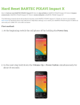
Dimensions and wall cut-out for keyboard
140.00 mm
390.00 mm
3.30 mm
150.00 mm
85.00 mm
100.00 mm
300.00 mm
400.00 mm
170.00 mm
420.00 mm
Hole diameter: 3.3 mm

User manual
POLARIS Panel PC 19.1'' and Panel PC 15''
Version 2.00 Page 14 of 46
E_BMS790_POLARIS_PanelPC_19+15_Rev1.doc • User manual for POLARIS Panel PC 19.1" and 15" • Revision 1 / Status: January, 3
rd
, 2006 • Technical data subject to change
2.6 Characteristics data mouse, trackball and touchpad
2.6.1 Mouse
Ex protection type
:
II 2G Ex ib IIC T4
Certification
: IBExU05ATEX1117 X
Type : 17-71VZ-10../....
Dimensions : 130 mm x 170 mm (weight x height)
Wall-cut out : 100 mm x 140 mm
Installation depth : 15 mm
Weight : approx. 270 g
2.6.2 Trackball
Ex protection type
:
II 2G Ex ib IIC T4
II 2D tD A21 T 80°C IP 6X (front side)
Certification
: IBExU05ATEX1117 X
Type : 17-71VZ-20../….
Dimensions : 130 mm x 170 mm (weight x height)
Wall-cut out : 100 mm x 140 mm
Installation depth : 43 mm
Weight : approx. 500 g
2.6.3 Touchpad
Ex protection type
:
II 2G Ex ib IIC T4
Certification
: IBExU05ATEX1117 X
Type : 17-71VZ-30../….
Dimensions : 130 mm x 170 mm (weight x height)
Wall-cut out : 100 mm x 140 mm
Installation depth : 15 mm
Weight : approx. 250 g

User manual
POLARIS Panel PC 19.1'' and Panel PC 15''
Version 2.00 Page 15 of 46
E_BMS790_POLARIS_PanelPC_19+15_Rev1.doc • User manual for POLARIS Panel PC 19.1" and 15" • Revision 1 / Status: January, 3
rd
, 2006 • Technical data subject to change
Dimensions and wall cut-out for mouse, trackball and touchpad
100.00 mm
140.00 mm
110.00 mm
3.30 mm
85.00 mm
170.00 mm
130.00 mm
150.00 mm
Hole diameter: 3.3 mm

User manual
POLARIS Panel PC 19.1'' and Panel PC 15''
Version 2.00 Page 16 of 46
E_BMS790_POLARIS_PanelPC_19+15_Rev1.doc • User manual for POLARIS Panel PC 19.1" and 15" • Revision 1 / Status: January, 3
rd
, 2006 • Technical data subject to change
3. Terminal assignment
3.1 Terminal assignment Ex e
Terminal Interface Signal Remarks
X10 Supply L AC 230 V ± 10 %
X11 Supply N Neutral
X12 Supply PE Protective earth
Configuration of RS422 interface of Ethernet 10BaseT
X13 Ethernet RxD + 10BaseT Receive positive
X14 Ethernet RxD - 10BaseT Receive negative
X15 Ethernet TxD + 10BaseT Transmit positive
X16 Ethernet TxD - 10BaseT Transmit negative
Configuration of RS422 interface
X17 Jumper between terminal X17 and X18 for
X18
Termination On/Off
activation of the terminator resistors
X19 Interface COM 1 TxD B (TxD+) Transmission cable Input
X20 Interface COM 1 TxD A (TxD-) Transmission cable Input
X21 Interface COM 1 RxD B (RxD+) Receiving cable Input
X22 Interface COM 1 RxD A (RxD-) Receiving cable Input
X23 Interface COM 1 TxD B (TxD+) Transmission cable Output
X24 Interface COM 1 TxD A (TxD-) Transmission cable Output
X25 Interface COM 1 RxD B (RxD+) Receiving cable Output
X26 Interface COM 1 RxD A (RxD-) Receiving cable Output
When interface used with PROFIBUS-DP interface in place of RS422:
Configuration of PROFIBUS-DP interface
Terminal Interface Signal Remarks
X17 GND PROFIBUS PE Additional ground
X18 not connected N.C.
X19 Interface COM 1 Termination B2 Bridge for terminating network (B1-B2)
X20 Interface COM 1 Termination A2 Bridge for terminating network (A1-A2)
X21 Interface COM 1 Termination B1 Bridge for terminating network (B1-B2)
X22 Interface COM 1 Termination A1 Bridge for terminating network (A1-A2)
X23 Interface COM 1 Out B Signal B Output
X24 Interface COM 1 Out A Signal A Output
X25 Interface COM 1 In B Signal B Input
X26 Interface COM 1 In A Signal A Input

User manual
POLARIS Panel PC 19.1'' and Panel PC 15''
Version 2.00 Page 17 of 46
E_BMS790_POLARIS_PanelPC_19+15_Rev1.doc • User manual for POLARIS Panel PC 19.1" and 15" • Revision 1 / Status: January, 3
rd
, 2006 • Technical data subject to change
3.2 Terminal assignment Ex i
Terminal Interface Colour Signal Remarks
Scanner connection
(optional)
X1 Hand-held scanner +UB Supply voltage +5 V
X2 Supply RxD-I Data input RS232 signal
X3 Supply GND Mass connected to protective earth
PS/2 interface for input devices
X4 PS2 WH/BN VCC Supply voltage
X5 PS2 GN/YE GND Mass connected to protective earth
X6 PS2 PK KB_CLK Keyboard clock signal
X7 PS2 GR KB_DATA Keyboard data signal
X8 PS2 BL MS_CLK Mouse clock signal
X9 PS2 RD MS_DATA Mouse data signal
3.3 Electrical installation
3.3.1 EMC notes
This device is class A equipment and may cause interference in domestic
electrical equipment. If this occurs, the installer of the device may be required to
implement appropriate counter measures.
All connection cables must be shielded. This applies both to data lines and to other cables.
The data cables must be twisted in pairs. Example: 2 x 2 x 0.75 mm² LIYCY TP.
If possible, cables for power supply and data must be laid separately.

User manual
POLARIS Panel PC 19.1'' and Panel PC 15''
Version 2.00 Page 18 of 46
E_BMS790_POLARIS_PanelPC_19+15_Rev1.doc • User manual for POLARIS Panel PC 19.1" and 15" • Revision 1 / Status: January, 3
rd
, 2006 • Technical data subject to change
3.3.2 Interference suppression
Certain basic measures must be taken to ensure freedom from interference when the POLARIS Panel PC are installed:
■ Interference voltages injected into the unit via power and signal cables and static charges
caused by contact are to be conducted to earth (e.g. grounding screw terminal fixed to the back
of the unit). This earthing point must be connected to the PE conductor by means of the
shortest possible low resistance copper conductor or must be integrated in the equipotential
bonding. If this point is not observed, the measures taken to suppress interference and
preclude damage to the device effectively will be impaired.
■ The installation point should be as far as possible away from fields of electromagnetic
interference. This is especially important if there are frequency converters in the vicinity. Under
certain circumstances it will be advisable to set up partitions to isolate the POLARIS Panel PC
from interference.
■ If inductive unit are fitted in the vicinity (e.g. contactor, relay or solenoid coils), especially if they
are powered from the same source, protective circuits (e.g. RC elements) must be installed.
■ Power supply and data cables must be laid so as to avoid interference. This can, for example,
be achieved by avoiding laying such cables in close proximity to high current carrying cables.
3.3.3 Shielding
■ Only cables with braided shielding should be used
(recommended cover density > 80%).
■ Sheet shielding should not be used.
■ Generally, connection of the shielding at both ends results in optimum damping of all
interference frequencies.
■ Connection of the shielding at one side only may be more advisable if a difference in
potential exists and no equipotential bonding cable can be laid.

User manual
POLARIS Panel PC 19.1'' and Panel PC 15''
Version 2.00 Page 19 of 46
E_BMS790_POLARIS_PanelPC_19+15_Rev1.doc • User manual for POLARIS Panel PC 19.1" and 15" • Revision 1 / Status: January, 3
rd
, 2006 • Technical data subject to change
3.3.4 Connection of shielding
■ A low impedance connection to the circuit protective conductor is important to ensure a low
current fault path.
■ When sub-D connectors are used, the shielding should always be connected to the metal
casing of the sub-D plug.
■ The plug casing of some controllers is not always well connected to earth. In such cases it
may prove advantageous to insulate the shielding from the sub-D plug of the controller and
connect it directly with the protective earth conductor by means of a cable that should be
kept as short as possible (0.75 mm² …1.5 mm²).
3.3.5 Examples of how shielding can be connected
Connection of shielding at both ends of the cables linking the controller and POLARIS Panel PC:
Generally, connection of the shielding at both ends results in optimum damping of all interference frequencies. This method
is to be recommended when there is good equipotential bonding between the individual units. In such cases it is possible to
make use of the controller’s voltage supply cable even if this is not electrically isolated.
Controller
Earth
POLARIS
Panel PC
Shielding

User manual
POLARIS Panel PC 19.1'' and Panel PC 15''
Version 2.00 Page 20 of 46
E_BMS790_POLARIS_PanelPC_19+15_Rev1.doc • User manual for POLARIS Panel PC 19.1" and 15" • Revision 1 / Status: January, 3
rd
, 2006 • Technical data subject to change
Connection of shielding at one end only of the cables linking the controller and Panel PC:
Connection of the shielding at one end only is recommended when there is inadequate equipotential bonding, or none at all.
In such cases an electrically isolated power supply unit must be used.
If the shielding were connected at both ends, the equipotential bonding current would flow to point A and this must be
avoided at all costs, as the resultant interference pulses could be passed on to the devices via the data cable. When
shielding is connected at one end only it must be on the side that has the lowest resistance earth connection.
Before the equipment goes into service the directions from the controller manufacturer regarding proper assembly and
operation must be read carefully. They should then be applied taking full account of the recommendations we make here.
3.3.6 Connection of Ethernet cable to POLARIS Panel PCs
Shielding
Controller
Difference in potential
Earth
POLARIS
Panel PC
/