CEN-TECH 69660 Owner's manual
- Category
- Power adapters & inverters
- Type
- Owner's manual
This manual is also suitable for
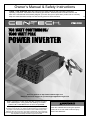
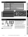
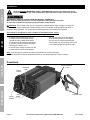
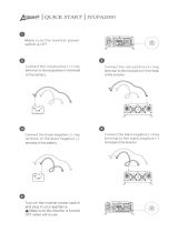
CEN-TECH 69660 is a 750-watt continuous power inverter with a surge power of 1500 watts. It has two 3-prong grounded polarized AC outlets and one 5 VDC 500mA USB outlet. You can safely use it for charging, powering, or running most sensitive electronics or small power tools. CEN-TECH 69660 is equipped with three internal blade-type 30 Amp fuses (professional replacement only). It is small and portable with dimensions of 9-1/4" L x 5-1/4" W x 2-1/2" H.
CEN-TECH 69660 is a 750-watt continuous power inverter with a surge power of 1500 watts. It has two 3-prong grounded polarized AC outlets and one 5 VDC 500mA USB outlet. You can safely use it for charging, powering, or running most sensitive electronics or small power tools. CEN-TECH 69660 is equipped with three internal blade-type 30 Amp fuses (professional replacement only). It is small and portable with dimensions of 9-1/4" L x 5-1/4" W x 2-1/2" H.


-
 1
1
-
 2
2
-
 3
3
-
 4
4
-
 5
5
-
 6
6
-
 7
7
-
 8
8
-
 9
9
-
 10
10
-
 11
11
-
 12
12


CEN-TECH 69660 Owner's manual
- Category
- Power adapters & inverters
- Type
- Owner's manual
- This manual is also suitable for
CEN-TECH 69660 is a 750-watt continuous power inverter with a surge power of 1500 watts. It has two 3-prong grounded polarized AC outlets and one 5 VDC 500mA USB outlet. You can safely use it for charging, powering, or running most sensitive electronics or small power tools. CEN-TECH 69660 is equipped with three internal blade-type 30 Amp fuses (professional replacement only). It is small and portable with dimensions of 9-1/4" L x 5-1/4" W x 2-1/2" H.
Ask a question and I''ll find the answer in the document
Finding information in a document is now easier with AI
Related papers
-
CEN-TECH 64867 Owner's manual
-
-
-
-
-
-
CEN-TECH 60322 User manual
-
-
-
Other documents
-
 Ampeak 8542130508 User guide
-
 Ampeak 13 User guide
-
Stanley PI500S User manual
-
Black & Decker 200 WATT User manual
-
Vector PI500V 500 WATT Power Inverter User manual
-
Armstrong Item 64977 Owner's manual
-
-
DeWalt DXAEPI1000 User manual
-
-
HARBOR FREIGHT 57333 User manual

