Page is loading ...

U
U
U
8
8
8
6
6
6
6
6
6
8
8
8
-
-
-
D
D
D
i
FCC Information and Copyright
This equipment has been tested and found to comply with the limits of a
Class B digital device, pursuant to Part 15 of the FCC Rules. These limits
are designed to provide reasonable protection against harmful
interference in a residential installation. This equipment generates, uses
and can radiate radio frequency energy and, if not installed and used in
accordance with the instructions, may cause harmful interference to radio
communications. There is no guarantee that interference will not occur in
a particular installation.
The vendor makes no representations or warranties with respect to the
contents here of and specially disclaims any implied
warranties of
merchantability or fitness for any purpose. Further the vendor reserves
the right to revise this publication and to make changes to the contents
here of without obligation to notify any party beforehand.
Duplication of this publication, in part or in whole, is not allowed without
first obtaining the vendor’s approval in writing.
The content of this user’s manual is subject to be changed without notice
and we will not be responsible for any mistakes found in this user’s
manual. All the brand and product names are trademarks of their
respective companies.

U
U
U
8
8
8
6
6
6
6
6
6
8
8
8
-
-
-
D
D
D
ii
ENGLISH...................................................................................................1
U8668-D Features.......................................................................................................1
Package contents.......................................................................................................2
Layout of U8668-D......................................................................................................3
Component Index.......................................................................................................4
CPU Installation..........................................................................................................5
DDR DIMM Modules: DDR1-2 ....................................................................................6
Jumpers, Headers, Connectors & Slots...................................................................7
ESPAÑOL ................................................................................................13
Características del U8668-D....................................................................................13
Contenido del Paquete ............................................................................................14
Disposición del U8668-D .........................................................................................15
Indice de los Componentes.....................................................................................16
Instalación de la CPU...............................................................................................17
Módulos DDR DIMM: DDR1-2..................................................................................18
Puentes, Cabezales, Conectores & Ranuras .........................................................19
FRANÇAIS ..............................................................................................25
Caractéristiques de U8668-D...................................................................................25
Contenu de l'Emballage...........................................................................................26
Dessin d’U8668-D.....................................................................................................27
WARPSPEEDER.....................................................................................28
Introduction ..............................................................................................................29
System Requirement................................................................................................29
Installation ................................................................................................................29
Usage ........................................................................................................................30
TROUBLE SHOOTING.........................................................................38
SOLUCIÓN DE PROBLEMAS.............................................................39

M
M
M
o
o
o
t
t
t
h
h
h
e
e
e
r
r
r
b
b
b
o
o
o
a
a
a
r
r
r
d
d
d
D
D
D
e
e
e
s
s
s
c
c
c
r
r
r
i
i
i
p
p
p
t
t
t
i
i
i
o
o
o
n
n
n
1
English
U8668-D Features
CPU
Provides Socket-478.
Supports the Intel Pentium 4 processor up to 3.06GHz.
Running at 400/533MHz Front Side Bus.
Supports Hyper-Treading.
Chipset
North Bridge: P4M266A
South Bridge: VT8235.
Main Memory
Supports up to 2 DDR devices.
Supports 200/266MHz DDR devices.
The largest memory capacity is 2GB.
Super I/O
Chipset: ITE IT8705F.
Slots
Two 32-bit PCI bus master slots.
One AMR slot.
One AGP slot.
On Board IDE
Supports four IDE disk drives.
Supports PIO Mode 4, Master Mode and Ultra DMA 33/66/100/133 Bus
Master Mode.
On Board VGA
Integrated Savage4 2D/3D Graphics Controller and Video Accelerator.
LAN
VT6103
Dual Speed: 10/100Mbps.
Full/Half Duplex.
Auto Negotiation : 10/100 Mbps, Full/Half Duplex.
On Board AC’97 Sound Codec
Compliant with AC’97 specification.
On Board Peripherals

M
M
M
o
o
o
t
t
t
h
h
h
e
e
e
r
r
r
b
b
b
o
o
o
a
a
a
r
r
r
d
d
d
D
D
D
e
e
e
s
s
s
c
c
c
r
r
r
i
i
i
p
p
p
t
t
t
i
i
i
o
o
o
n
n
n
2
Supports 360K, 720K, 1.2MB, 1.44MB and 2.88MB floppy disk drivers.
Supports 1 serial port.
Supports 1 multi-mode parallel port. (SPP/EPP/ECP mode)
Supports PS/2 mouse and PS/2 keyboard.
Supports 2 back USB2.0 ports and 4 front USB2.0 ports.
BIOS
AWARD legal Bios.
Supports APM1.2.
Supports ACPI.
Supports USB Function.
Operating System
Offers the highest performance for MS-DOS, Windows 2000, Windows Me,
Windows XP, SCO UNIX etc.
Dimensions
Flex Form Factor: 19.5cm X22.8cm. (W X L)
Package contents
HDD Cable X1
FDD Cable X1
Flash Memory Writer for BIOS Update X1
USB Cable X1 (Optional)
Rear I/O Panel for Flex Case X1 (Optional)
Fully Setup Driver CD X1

M
M
M
o
o
o
t
t
t
h
h
h
e
e
e
r
r
r
b
b
b
o
o
o
a
a
a
r
r
r
d
d
d
D
D
D
e
e
e
s
s
s
c
c
c
r
r
r
i
i
i
p
p
p
t
t
t
i
i
i
o
o
o
n
n
n
3
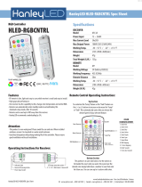
Layout of U8668-D
Soket 478
CPU
JKBMS1
K/B
&
Mouse
JVGA1
COM1
Parallel Port
JCOM1
JPRNT1
VGA
P4M266A
LAN
JGAME1
JWOL1
JCDIN1
AMR1
PCI2
PCI1
AGP1
FDD1
BAT
JSFAN1
JPANEL1
JCI1
IDE1
IDE2
DDR1
DDR2
JCFAN1
JCMOS1
JSPDIFO1
JUSB2
JATXPWR1
JATXPWR2
JAUDIO
JUSBLAN1
USB
&
LAN
Codec
JAUDIO1
1
1
2
15
16
1
1
1
1
1
1
1
2
23
24
1
1
Super
I/O

M
M
M
o
o
o
t
t
t
h
h
h
e
e
e
r
r
r
b
b
b
o
o
o
a
a
a
r
r
r
d
d
d
D
D
D
e
e
e
s
s
s
c
c
c
r
r
r
i
i
i
p
p
p
t
t
t
i
i
i
o
o
o
n
n
n
4
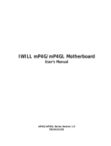
Component Index
A. Back Panel Connectors K. System Fan Connector (JSFAN1)
B. Front Audio Header (JAUDIO1) L. Front Panel Connectors (JPANEL1)
C. Front USB Header (JUSB2) M. Case Open Connector (JCI1)
D. PCI Slots (PCI1-2) N. Clear CMOS (JCMOS1)
E. GAME Header (JGAME1):optional O. IDE Connectors (IDE1-2)
F. Wake OnLAN Header (JWOL1) P. ATX Power Connector (JATXPWR1-2)
G. CD-ROM Audio-In Header (JCDIN1) Q. DDRs (DDR1-2)
H. AMR Slot (AMR1) R. CPU Fan Connector (JCFAN1)
I. Floppy Disk Connector (FDD1) S. AGP Slot (AGP1)
J. Digital Audio Connector (JSPDIFO1)
P4M266A
Codec
JGAME1
A
B
C
D
E
F
G
H
I
J
K
L
M
O
P
N
R
S
Super
I/O
BIOS
LAN

M
M
M
o
o
o
t
t
t
h
h
h
e
e
e
r
r
r
b
b
b
o
o
o
a
a
a
r
r
r
d
d
d
D
D
D
e
e
e
s
s
s
c
c
c
r
r
r
i
i
i
p
p
p
t
t
t
i
i
i
o
o
o
n
n
n
5
CPU Installation
1. Pull the lever sideways away from the socket then raise the lever up to a
90-degree angle.
2. Locate Pin A in the socket and look for the white dot or cut edge in the CPU.
Match Pin A with the white dot/cut edge then insert the CPU.
3. Press the lever down. Then Put the fan on the CPU and buckle it and put the
fan’s power port into the JCFAN1, then to complete the installation.
CPU/ System Fan Headers: JCFAN1/ JSFAN1
JCFAN1
1
Ground
12V
Sense
JSFAN1
1
Ground
12V
Sense
CPU Fan
CPU

M
M
M
o
o
o
t
t
t
h
h
h
e
e
e
r
r
r
b
b
b
o
o
o
a
a
a
r
r
r
d
d
d
D
D
D
e
e
e
s
s
s
c
c
c
r
r
r
i
i
i
p
p
p
t
t
t
i
i
i
o
o
o
n
n
n
6
DDR DIMM Modules: DDR1-2
DRAM Access Time: 2.5V Unbuffered/ Registered DDR 200 MHz (PC1600)/
DDR 266 MHz (PC2100) Type required.
DRAM Type: 64MB/ 128MB/ 256MB/ 512MB/ 1GB DIMM Module.(184 pin)
DIMM Socket
Location
DDR Module Total Memory
Size (MB)
DDR 1 64MB/128MB/256MB/512MB/1GB
*1
DDR 2 64MB/128MB/256MB/512MB/1GB
*1
Max is
2GB
! The list shown above for DRAM configuration is only for reference.
How to install DDR DIMM Module
1. The DDR DIMM socket has a “ Plastic
Safety Tab”, and the DDR DIMM memory
module has an Asymmetrical notch”, so the
DDR DIMM memory module can only fit into
the slot in one direction.
2. Push the tabs out. Insert the DDR DIMM
memory modules into the socket at a
90-degree angle, then push down vertically
so that it will fit into the place.
3. The Mounting Holes and plastic tabs
should fit over the edge and hold the DDR
DIMM memory modules in place.

M
M
M
o
o
o
t
t
t
h
h
h
e
e
e
r
r
r
b
b
b
o
o
o
a
a
a
r
r
r
d
d
d
D
D
D
e
e
e
s
s
s
c
c
c
r
r
r
i
i
i
p
p
p
t
t
t
i
i
i
o
o
o
n
n
n
7
Jumpers, Headers, Connectors & Slots
Hard Disk Connectors: IDE1/ IDE2
The motherboard has a 32-bit Enhanced PCI IDE Controller that provides PIO
Mode 0~4, Bus Master, and Ultra DMA 33/ 66/ 100/ 133 functionality. It has two
HDD connectors IDE1 (primary) and IDE2 (secondary).
The IDE connectors can connect a master and a slave drive, so you can connect
up to four hard disk drives. The first hard drive should always be connected to
IDE1.
Floppy Disk Connector: FDD1
The motherboard provides a standard floppy disk connector that supports 360K,
720K, 1.2M, 1.44M and 2.88M floppy disk types. This connector supports the
provided floppy drive ribbon cables.
Audio Modem Riser Slot: AMR1
(Only support slave card)
The AMR specification is an open Industry Standard Architecture and that defines
a hardware scalable riser card interface, which supports audio and modem only.
Peripheral Component Interconnect Slots: PCI1-2
This motherboard is equipped with 2 standard PCI slots. PCI stands for Peripheral
Component Interconnect, and it is a bus standard for expansion cards. This PCI
slot is designated as 32 bits.
Accelerated Graphics Port Slot: AGP1
Your monitor will attach directly to that video card. This motherboard supports
video cards for PCI slots, but it is also equipped with an Accelerated Graphics Port
(AGP). An AGP card will take advantage of AGP technology for improved video
efficiency and performance, especially with 3D graphics.
Front USB Header: JUSB2
JUSB1/2
2
1
Pin Assignment Pin Assignment
12
43
56
87
910
+5V +5V
Data (-)Data (-)
Data (+) Data (+)
Ground Ground
Key NA

M
M
M
o
o
o
t
t
t
h
h
h
e
e
e
r
r
r
b
b
b
o
o
o
a
a
a
r
r
r
d
d
d
D
D
D
e
e
e
s
s
s
c
c
c
r
r
r
i
i
i
p
p
p
t
t
t
i
i
i
o
o
o
n
n
n
8
Power Connectors: JATXPWER1/ JATXPWR2
JATXPWR1
PIN Assignment PIN Assignment
1 +3.3V 11 +3.3V
2 +3.3V 12 -12V
3 Ground 13 Ground
4 +5V 14 PS_ON
5 Ground 15 Ground
6 +5V 16 Ground
7 Ground 17 Ground
8 PW_OK 18 -5V
9 +5V_SB 19 +5V
10 +12V 20 +5V
JATXPWR2
PIN Assignment PIN Assignment
1 12V 3 Ground
2 12V 4 Ground
JATXPWR1
(ATX Main Power Connector)
JATXPWR2
(ATX 12V Power Connector)

M
M
M
o
o
o
t
t
t
h
h
h
e
e
e
r
r
r
b
b
b
o
o
o
a
a
a
r
r
r
d
d
d
D
D
D
e
e
e
s
s
s
c
c
c
r
r
r
i
i
i
p
p
p
t
t
t
i
i
i
o
o
o
n
n
n
9
Front Panel Connector: JPANEL1
Clear CMOS Jumper: JCMOS
※
Clear CMOS Procedures:
1. Remove AC power line.
2. Make JCMOS1 (2-3) closed.
3. Wait for five seconds.
4. Make JCMOS1 (1-2) closed.
5. Let AC power on.
6. Reset your desired password or clear the CMOS data.
SPK
PWR
_
LED
HLED
SLP
RST
2
24
IR
1
23
IRON/OFF
SPK ==> S
p
eaker Conn.
HLED ==> Hard Driver LED
RST ==> Reset Button
IR ==> Infrared Conn.
SLP ==> Sleep Button
PWR_LED ==> Power LED
ON/ OFF ==> Power-on Button
(+) (-)
(+) (-)(+)
JCMOS
Clear CMOS
Data
Pin 1-2 on
Normal
Operation
(default)
Assignment
1
Pin 2-3 on
1

M
M
M
o
o
o
t
t
t
h
h
h
e
e
e
r
r
r
b
b
b
o
o
o
a
a
a
r
r
r
d
d
d
D
D
D
e
e
e
s
s
s
c
c
c
r
r
r
i
i
i
p
p
p
t
t
t
i
i
i
o
o
o
n
n
n
10
Audio Subsystem: JAUDIO1/ JCDIN1
! JF_AUDIO1 only support 2CH.
2
JF_AUDIO1
1
2
10
9
Pin
1
3
5
7
9
Pin
2
4
6
8
10
Mic In
Mic Power
RT Line Out
Reserved
LFT Line Out
Assignment
Ground
Audio Power
RT Line Out
Key
Assignment
LFT Line Out
1
2
JAUDIO1
(Front Audio Header)
1
JCDIN1
(CD-ROM Audio-In Header)
1
2
JAUDIO1
(Front Audio Header)
1
JCDIN1
(CD-ROM Audio-In Header)
12
Front Panel Audio Connector/ Jumper Block
9
10
Audio line out signals are routed to
the back panel audio line out connector.
Pin 5 and 6
Pin 9 and 10
Audio line out and mic in signals are
available for front panel audio connectors.
3
5
7
4
6
12
9
10
3
5
7
4
6
No jumpers
installed
Jumper Setting Configuration

M
M
M
o
o
o
t
t
t
h
h
h
e
e
e
r
r
r
b
b
b
o
o
o
a
a
a
r
r
r
d
d
d
D
D
D
e
e
e
s
s
s
c
c
c
r
r
r
i
i
i
p
p
p
t
t
t
i
i
i
o
o
o
n
n
n
11
Game Header: JGAME1
Digital Audio Connector: JSPDIFO1
Wake OnLAN Header :JWOL1
1
216
15
JGAME1
Pin Assignment PinAssignment
1
34
5
7
9
2
6
8
10
12
13
11
14
1615
+5V +5V
GP4GP6
GP2 GP0
Ground
MIDI-OUTR
GP3 Ground
GP1
GP5
+5V
GP7
MIDI-INR
NC
JSPDIF_OUT
1
SPDIF
_
Out
5VGND
1
5V
JWOL1
Ground
Wake u
p

M
M
M
o
o
o
t
t
t
h
h
h
e
e
e
r
r
r
b
b
b
o
o
o
a
a
a
r
r
r
d
d
d
D
D
D
e
e
e
s
s
s
c
c
c
r
r
r
i
i
i
p
p
p
t
t
t
i
i
i
o
o
o
n
n
n
12
Case Open Connector: JCI1
Back Panel Connectors
PS/2
Keyboard
PS/2
Mouse
COM1
JPRNT1
JCOM1
JKBMS1
USB
JUSB1 JVGA1
USB
JUSBLAN2
Speaker Out
Line In
Mic In
JAUDIO
LAN
Parallel
VGA
Normal
Operation
(default)
AssignmentJCI1
Case Open
No jumper
installed
Normal
Operation
(
default
)
Assignment
1
Pin 1-2 on
1

M
M
M
o
o
o
t
t
t
h
h
h
e
e
e
r
r
r
b
b
b
o
o
o
a
a
a
r
r
r
d
d
d
D
D
D
e
e
e
s
s
s
c
c
c
r
r
r
i
i
i
p
p
p
t
t
t
i
i
i
o
o
o
n
n
n
13
Español
Características del U8668-D
CPU
Proporciona Socket-478.
Soporta procesador Intel Pentium 4 de hasta 3.06GHz.
Corre a 400/ 533MHz Front Side Bus.
Soporta Hyper-Threading.
Chipset
North Bridge: P4M266A
South Bridge: VT8235.
Memoria Principal
Soporta hasta 2 dispositivos DDR.
Soporta dispositivos DDR de 200/ 266MHz.
Capacidad máxima de memoria 2GB.
Super I/O
Chipset: ITE IT8705F.
Ranuras
Dos ranuras de 32-bit PCI bus master.
Una ranura AMR.
Una ranura AGP.
IDE Onboard
Soporta cuarto discos IDE.
Soporta Modos PIO 4, Modo Master y Modo Ultra DMA 33/66/100/133 Bus
Master.
VGA Onboard
Integrated Savage4 2D/3D Controlador Gráfico y Acelerador de Video.
LAN
VT6103
Dual Speed: 10/100Mbps.
Full/Half Duplex.
Auto Negociación : 10/100 Mbps, Full/Half Duplex.
AC’97 Sound Codec Onboard
Constituye con la especificación del AC’97.
Periféricos Onboard
Soporta disquette de 360K, 720K, 1.2MB, 1.44MB y 2.88MB.

M
M
M
o
o
o
t
t
t
h
h
h
e
e
e
r
r
r
b
b
b
o
o
o
a
a
a
r
r
r
d
d
d
D
D
D
e
e
e
s
s
s
c
c
c
r
r
r
i
i
i
p
p
p
t
t
t
i
i
i
o
o
o
n
n
n
14
Soporta 1 puerto serie.
Soporta 1 puerto paralelo multi-mode. (modo SPP/EPP/ECP)
Soporta ratón PS/2 y teclado PS/2.
Soporta 2 puertos USB2.0 traseros y 4 puertos USB2.0 frontales.
BIOS
AWARD legal Bios.
Soporta APM1.2.
Soporta ACPI.
Soporta función USB.
Sistemas Operativos
Ofrece el más alto funcionamiento para MS-DOS, Windows 2000, Windows
Me, Windows XP, SCO UNIX etc.
Dimensiones
Factor de Forma Flex: 19.5cm X22.8cm. (W X L)
Contenido del Paquete
Cable HDD X1
Cable FDD X1
Flash Memory Writer para actualización del BIOS X1
Cable USB X1 (Opcional)
Panel Trasero I/O para carcasa Flex X1 (Opcional)
Configuración completa del Driver CD X1

M
M
M
o
o
o
t
t
t
h
h
h
e
e
e
r
r
r
b
b
b
o
o
o
a
a
a
r
r
r
d
d
d
D
D
D
e
e
e
s
s
s
c
c
c
r
r
r
i
i
i
p
p
p
t
t
t
i
i
i
o
o
o
n
n
n
15
Disposición del U8668-D
Soket 478
CPU
JKBMS1
Teclado
&
Raton
JVGA1
COM1
Puerto Paralelo
JCOM1
JPRNT1
VGA
P4M266A
LAN
JGAME1
JWOL1
JCDIN1
AMR1
PCI2
PCI1
AGP1
FDD1
BAT
JSFAN1
JPANEL1
JCI1
IDE1
IDE2
DDR1
DDR2
JCFAN1
JCMOS1
JSPDIFO1
JUSB2
JATXPWR1
JATXPWR2
JAUDIO
JUSBLAN1
USB
&
LAN
Codec
JAUDIO1
1
1
2
15
16
1
1
1
1
1
1
1
2
23
24
1
1
Super
I/O

M
M
M
o
o
o
t
t
t
h
h
h
e
e
e
r
r
r
b
b
b
o
o
o
a
a
a
r
r
r
d
d
d
D
D
D
e
e
e
s
s
s
c
c
c
r
r
r
i
i
i
p
p
p
t
t
t
i
i
i
o
o
o
n
n
n
16
Indice de los Componentes
A. Conectores del Panel Trasero
K. Conector del Sistema de Ventilación
(JSFAN1)
B. Cabezal Frontal de Audio (JAUDIO1)
L. Conectores del Panel Frontal
(JPANEL1)
C. Cabezal Frontal USB (JUSB2) M. Conector de la Carcasa Abierta (JCI1)
D. Ranuras PCI (PCI1-2) N. Borrar CMOS (JCMOS1)
E. Cabezal de Juego (JGAME1):opcional O. Conectores IDE (IDE1-2)
F. Cabezal Wake On LAN (JWOL1)
P. Conector de Corriente ATX
(JATXPWR1-2)
G. Cabezal de Entrada de Audio del
CD-ROM (JCDIN1)
Q. DDRs (DDR1-2)
H. Ranura AMR (AMR1)
R. Conector de Ventilación del CPU
(JCFAN1)
I. Conector para disquetera (FDD1) S. Ranura AGP (AGP1)
J. Conector de Audio Digital (JSPDIFO1)
P4M266A
Codec
JGAME1
A
B
C
D
E
F
G
H
I
J
K
L
M
O
P
N
R
S
Super
I/O
BIOS
LAN

M
M
M
o
o
o
t
t
t
h
h
h
e
e
e
r
r
r
b
b
b
o
o
o
a
a
a
r
r
r
d
d
d
D
D
D
e
e
e
s
s
s
c
c
c
r
r
r
i
i
i
p
p
p
t
t
t
i
i
i
o
o
o
n
n
n
17
Instalación de la CPU
1. Tire de la palanca del lado del zócalo, luego levante la palanca hasta un ángulo
de 90 grados.
2. Sitúe el contacto A del zócalo y busque el punto blanco o corte el borde en la
CPU. Empareje el contacto A con el punto blanco/ corte del borde, luego inserte
la CPU.
3. Presione la palanca para abajo. Ponga el ventilador en la CPU y abróchelo.
Luego ponga el puerto de corriente del ventilador en el JCFAN1. Y ya habrá
completado su instalación.
CPU/ Cabezales del Sistema de Ventilación: JCFAN1/ JSFAN1
CPU Fan
CPU
JCFAN1
1
Tierra
12V
Sense
JSFAN1
1
Tierra
12V
Sense

M
M
M
o
o
o
t
t
t
h
h
h
e
e
e
r
r
r
b
b
b
o
o
o
a
a
a
r
r
r
d
d
d
D
D
D
e
e
e
s
s
s
c
c
c
r
r
r
i
i
i
p
p
p
t
t
t
i
i
i
o
o
o
n
n
n
18
Módulos DDR DIMM: DDR1-2
DRAM Tiempo de Acceso: 2.5V Unbuffered/ Registered DDR 200 MHz
(PC1600)/ DDR 266 MHz (PC2100) Tipo requerido.
DRAM Tipo: 64MB/ 128MB/ 256MB/ 512MB/ 1GB Módulo DIMM.(contactos 184)
Localización del
Socket DIMM
Módulo DDR Total del
Tamaño de
Memoria (MB)
DDR 1 64MB/128MB/256MB/512MB/1GB
*1
DDR 2 64MB/128MB/256MB/512MB/1GB
*1
Máxima 2GB
! La lista de arriba para la configuración DRAM es solamente para referencia.
Cómo instalar un Módulo DDR DIMM
1. El zócalo DIMM tiene una lengüeta
plástica de seguridad y el módulo de
memoria DIMM tiene una muesca asimétrica,
así el módulo de memoria DIMM puede
caber solamente en la ranura de una sóla
dirección.
2. Tire la lengüeta hacia afuera. Inserte los
módulos de memoria DIMM en el zócalo a
los 90 grados, luego empuje hacia abajo
verticalmente de modo que encaje en el
lugar.
3. Los agujeros de montaje y las lengüetas
plásticas deben caber por sobre el borde y
sostenga los módulos de memoria DIMM en
el lugar.
/