OWNER’S MANUAL
Close Coupled Motor Drive Self
Priming Centrifugal Pump
© 2014 F00628 (03/03/14)
B2X, B3T, B4T, B4Z
Important
For best possible performance and continuous, satisfactory operation,
read these instructions before installing your new pump.
Should service be required, this manual can be a valuable guide.
It should be kept near the installation for ready reference.

Safety 2
Important Safety Instructions
SAVE THESE INSTRUCTIONS - This manual contains
important instructions that should be followed during
installation, operation, and maintenance of the product.
Save this manual for future reference.
This is the safety alert symbol. When you see this
symbol on your pump or in this manual, look for one of
the following signal words and be alert to the potential
for personal injury!
indicates a hazard which, if not avoided, will
result in death or serious injury.
indicates a hazard which, if not avoided,
could result in death or serious injury.
indicates a hazard which, if not avoided,
could result in minor or moderate injury.
NOTICE addresses practices not related to
personalinjury.
The manufacturer cannot anticipate every possible
circumstance that might involve a hazard. The warnings
in this manual, and the tags and decals affixed to the unit
are, therefore, not all-inclusive. If you use a procedure
or operating technique that the manufacturer does not
specifically recommend, you must satisfy yourself that it
is safe for you and others. You must also make sure that
the procedure or operating technique that you choose
does not render the system unsafe.
To avoid risk of serious bodily injury and property
damage, read and follow all safety instructions in this
manual and on equipment carefully before installing this
pump. Keep safety labels in good condition; replace if
missing or damaged.
Electrical Safety
Risk of electric shock. Can shock, burn or
kill. All wiring should be done by a qualified electrician.
• Wiremotorforcorrectvoltage.See“Electrical”
section of this manual and motor nameplate.
• Groundmotorbeforeconnectingtopowersupply.
• MeetNationalElectricalCodeandlocalcodesfor
allwiring.
• Followwiringinstructionsinthismanualwhen
connecting motor to power lines.
General Safety
Risk of explosion. The pump body may
explode if used to boost pressure above 100 psi
(689kPa). Do not use this pump with inlet pressure
greater than 70 psi (483 kPa). If not already in the
piping system, install a pressure relief valve in the pump
discharge line capable of passing the full pump flow at
100 psi (689 kPa). If local code requires installation of a
pressure relief valve capable of handling the full pump
flow at a pressure less than 100 psi (689 kPa), follow the
code requirements.
Risk of fire or explosion. To avoid risk of
fire and explosion, Pump Water Only with this pump. Do
not pump salt water, flammable liquids or chemicals. Do
not use the pump near gas pilot lights or where chemical
or gas fumes are present. Use of an electric pump with
liquids other than water or in an atmosphere containing
chemical or gas fumes may ignite those liquids or
gases and cause injury or death due to an explosion
and/orfire.
Heavy parts.NEVERwalkorreachundera
suspended pump.
• DONOTscrewaneyeboltintothemotorhousing
and attempt to lift assembly! The lifting point built
into the motor case is not designed to support the
combined weight of the motor and pump.
• Thecraneorhoistmusthaveacapacityinexcessof
the combined weight of the motor and pump.
Risk of burns. If water is trapped in the pump
during operation it may turn to steam. Trapped steam
canleadtoanexplosionandburns.Neverrunthepump
with the outlet closed or obstructed.
Risk of freezing. Do not allow pump, piping,
or any other system component containing water to
freeze. Freezing may damage system, leading to injury or
flooding. Allowing pump or system components to freeze
will void warranty.
Pump approved liquids only with this pump.
Periodically inspect pump and system components.
Wear safety glasses at all times when working on pumps.
Keep work area clean, uncluttered and properly lighted;
store properly all unused tools and equipment.
Keep visitors at a safe distance from the work areas.
Makeworkshopschildproof;usepadlocksandmaster
switches; remove starter keys.
California Proposition 65 Warning
This product and related accessories contain
chemicals known to the State of California to cause
cancer, birth defects or other reproductive harm.

Warranty 3
Limited Warranty
BERKELEYwarrantstotheoriginalconsumerpurchaser(“Purchaser”or“You”)oftheproductslistedbelow,thattheywillbefree
from defects in material and workmanship for the Warranty Period shown below.
Product Warranty Period
Water Systems:
Water Systems Products — jet pumps, small centrifugal pumps, submersible pumps and
related accessories
whichever occurs first:
12 months from date of original installation, or
18 months from date of manufacture
Pro-Source™ Composite Tanks 5 years from date of original installation
Pro-Source™ Steel Pressure Tanks 5 years from date of original installation
Pro-Source™Epoxy-LinedTanks 3 years from date of original installation
Sump/Sewage/EffluentProducts
12 months from date of original installation, or
18 months from date of manufacture
Agricultural/Commercial:
Centrifugals–close-coupledmotordrive,framemount,SAEmount,enginedrive,VMS,
SSCX,SSHM,solidshandling,submersiblesolidshandling
12 months from date of original installation, or
24 months from date of manufacture
SubmersibleTurbines,6”diameterandlarger
12 months from date of original installation, or
24 months from date of manufacture
Our limited warranty will not apply to any product that, in our sole judgement, has been subject to negligence, misapplication,
improper installation, or improper maintenance. Without limiting the foregoing, operating a three phase motor with single phase
powerthroughaphaseconverterwillvoidthewarranty.Notealsothatthreephasemotorsmustbeprotectedbythree-leg,
ambient compensated, extra-quick trip overload relays of the recommended size or the warranty is void.
Youronlyremedy,andBERKELEY’sonlyduty,isthatBERKELEYrepairorreplacedefectiveproducts(atBERKELEY’schoice).You
must pay all labor and shipping charges associated with this warranty and must request warranty service through the installing
dealerassoonasaproblemisdiscovered.NorequestforservicewillbeacceptedifreceivedaftertheWarrantyPeriodhas
expired. This warranty is not transferable.
BERKELEYSHALLNOTBELIABLEFORANYCONSEQUENTIAL,INCIDENTAL,ORCONTINGENTDAMAGESWHATSOEVER.
THEFOREGOINGLIMITEDWARRANTIESAREEXCLUSIVEANDINLIEUOFALLOTHEREXPRESSANDIMPLIED
WARRANTIES,INCLUDINGBUTNOTLIMITEDTOIMPLIEDWARRANTIESOFMERCHANTABILITYANDFITNESSFOR
APARTICULARPURPOSE.THEFOREGOINGLIMITEDWARRANTIESSHALLNOTEXTENDBEYONDTHEDURATION
PROVIDEDHEREIN.
Some states do not allow the exclusion or limitation of incidental or consequential damages or limitations on the duration of an
implied warranty, so the above limitations or exclusions may not apply to You. This warranty gives You specific legal rights and
You may also have other rights which vary from state to state.
ThisLimitedWarrantyiseffectiveJune1,2011andreplacesallundatedwarrantiesandwarrantiesdatedbeforeJune1,2011.
In the U.S.: BERKELEY, 293 Wright St., Delavan, WI 53115
In Canada: 269 Trillium Dr., Kitchener, Ontario N2G 4W5

Installation 4
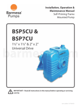
Motor / Pump Lifting Procedure:
Heavy parts.NEVERwalkorreachundera
suspendedpump.DONOTscrewaneyeboltintothe
motor housing and attempt to lift assembly!
The crane or hoist must have a capacity in excess of
the combined weight of the motor and pump. Use a
minimum of two chains or straps to lift motor/pump
assembly.Eachchainorstrapmusthaveacapacityin
excess of the combined weight of the motor and pump.
Wrap the first chain or strap under the fan end of the
motor up tight against the motor feet, and the second
chain or strap under the pump bracket between the
pump end and the motor.
Raisemotor/pumpassemblyslowlytoensurethatthe
chains or straps will not slip when put under tension.
Balance motor and pump with chains or straps to
maintain proper weight distribution. If not balanced,
release tension on the chains or straps and readjust.
Figure 1 - Lifting the assembly
6507 0212

Installation 5
Location
Locatethepumpasnearthewatersourceaspractical.
Makethepiperunasshortandstraightaspossible,
especially if a suction lift is required.
Careful attention should be taken to assure that net
positivesuctionheadavailable(NPSHA)exceedsnet
positivesuctionheadrequired(NPSHR)bythepump
or reduced performance and severe pump damage may
result. If in doubt, check with your nearest Berkeley
professional dealer. Install pump in a clean, dry and
drained location readily accessible for inspection and
maintenance. Provide ample ventilation.
Pump Foundation
Heavy parts. Use care and proper equipment
when handling pump for installation. Pump should be set
on a concrete foundation which is sufficiently substantial
to absorb vibration and which provides a permanent and
rigid support.
There are several types of permanent pump / foundation
installations in use. Those pictured here are typical.
• Ifgroutisused,topofconcreteshouldbeleftrough
to provide a good bonding surface.
• Foundationshouldslopeawayfrompumptoprevent
liquid from pooling.
Piping
System piping should be at least one commercial pipe
size larger than pump connections and flow velocity
should not exceed eight (8) feet per second.
NOTICE Take care to align piping with pump case.
Misalignmentorexcessivepipestraincancause
distortion of pump components resulting in rubbing,
breakage and reduced pump life.
Support pipe in such a way that no force is exerted on
pump connections. Check alignment as follows: with the
pump shut down and isolation valves closed, remove
pipe flange bolts. If the mating flanges come apart or
shift, misalignment is present and causing pressure
on the connections. Adjust pipe supports until flanges
mate without any force. This procedure can be done
throughout piping system.
Refertothefollowingpagesforrecommendedand
not recommended practices in suction connections in
centrifugal installations.
797 0212
Pump or
Motor Frame
1/2" or thicker
Sole Plate tapped
for hold down bolts
Anchor
Bolts
Concrete Foundation
Pump or
Motor Frame
Alignment
Shims
Anchor
Bolt
Steel
Channel
Concrete
Foundation
Grout
Grout
Dam
Drainage
Wedges
Various Heights
Tack
Weld
Concrete
Foundation
Shims

Short length of straight pipe after reducer.
( 2 times pipe diameter minimum )
Suction
Gauge
Straight run, short as possible but
at least 6 times pipe diameter ("D")
after elbow to stabilize flow.
As close
as possible
Pipe diameter ("D")
4 x "D"
minimum
1 x "D" minimum
from bottom
Eccentric Reducer
flat side up.
See Foundation
section.
Support pipe
as required
NOTICE: All connections
must be air tight.
Standard or long
radius elbow.
Slope upward
to pump.
2114 0212
Strainer prevents debris
from entering pump
suction and prevents
entrapment hazard.
Foot valve maintains
pump prime after shutoff.
Installation 6
Recommended
For Suction Lift Applications:
• Usepipe,tubing,orreinforcedhoseto
make suction connection. Hose must have
sufficient strength to resist collapse under
the pressure differential that occurs while
pump is running.
• Suctionpipesizeshouldbeatleastone
commercial pipe size larger than opening
of pump inlet. Flow velocity should not
exceed 8 ft./sec.
• Suctionscreenmustscreenoutsolidsthat
could clog pump impeller.
• Suctionscreenareamustbeatleastfour
times suction pipe area.
• NetPositiveSuctionHeadAvailable
(NPSHA)mustexceedNetPositiveSuction
HeadRequired(NPSHR)bythepumpor
reduced performance and severe pump
damage may result.
• Allsuctionpipingmusthavecontinuous
rise to the pump suction inlet. A 1/4 inch
per foot minimum slope is recommended.

Do not use
Concentric
Reducer.
Concentric Reducer causes high spots
along the suction line resulting in
air pockets.
Long run
not recommended
Unsupported
pipe causes
excessive stress
on pump and fittings.
Excess use of pipe fittings
means potential
air leaks.
No support or
uneven mounting
not recommended.
Pipe diameter
("D") undersized
reduces performance
High suction
lift should
be avoided.
Less than
4 x "D"
Vortex caused by
insufficient submergence
may cause pump to
lose prime.
No strainer
may cause
pump to
clog.
Insufficient bottom
clearance
Elbow immediately in
front of pump intake
not recommended.
2115 0212
Do not install valves
in suction line.
Installation 7
For Suction Lift Applications:
• Suctionpipeslopingdownwardtopumpinletwill
trap air which will reduce performance and may
cause pump to lose prime.
• Suctionpipingthatisundersizedwillcreateexcess
friction losses that may cause cavitation and a
reduction in pump performance.
• Excessfittingsandbendsinsuctionlineresultsin
trapped air, reduced performance, and high friction
losses which may cause cavitation.
Risk of suction entrapment. Strainer must
beused.
NOT Recommended

See Foundation
section.
2214 0212
Water under
pressure
Support pipe
as required
Short run of straight pipe after
reducer (2 times pipe diameter).
Eccentric Reducer
flat side up.
Isolation Valve
full open when
pumping.
Standard or
long radius
elbow.
Suction
Gauge
Straight run, short as possible but
at least 6 times pipe diameter after
pipe fitting to stabilize flow.
Slope upward to pump.
Maintain minumum
liquid level to prevent
vortexing.
Installation 8
For Flooded Suction Applications:
• Usepipe,tubing,orreinforcedhosetomakesuction
connection. Hose must have sufficient strength
to resist collapse under the atmospheric pressure
differential that may occur while pump is running.
• Itisimportant,evenwithafloodedsuction
condition, that proper pipe fittings are used so water
is delivered to impeller eye with a smooth flow and
consistent velocity.
• Suctionpipesizeshouldbeatleastonecommercial
pipe size larger than opening of pipe inlet. Flow
velocity should not exceed 8 ft./sec.
• Anisolationvalveisusedinapressurizedsuction
pipe to permit servicing pump.
• Pipingrunandconnectionfittingsshouldbe
properly aligned and independently supported to
reduce strain on pump case.
• Ifsolidsarepresent,astrainershouldbeusedto
protect the pump.
Recommended

2215 0212
Inverted Eccentric Reducer
may result in air pocket.
Check Valve
in suction pipe
not needed.
Unsupported pipe causes
excessive stress on pump
and fittings.
Concentric Reducer may
cause air pockets.
Valve in upward
position may trap air.
Do not make elbow
connection directly
to pump suction.
Miter elbow or short
radius elbow not
recommended.
Water under
pressure
Do not leave
valve partially
closed.
Installation 9
For Flooded Suction Applications:
• Suctionpipingthatisundersizedwillcreateexcess
friction losses that may cause cavitation and a
reduction in pump performance.
• Excessfittingsandbendsinsuctionlineresultsin
trapped air, reduced performance, and high friction
losses which may cause cavitation.
• Ifcheckvalveisrequiredforbackflowprevention,
locate on the discharge side of pump.
NOT Recommended

Use Concentric Reducer
to mimimize friction losses.
Support piping
as required
Non-Slam or
spring loaded
check valve.
Isolation valve to
permit servicing of
check valve or pump.
Align piping to
minimize flange
stress.
Pressure
Gauge
Discharge pipe diameter
at least one nominal pipe
size larger than discharge
opening in pump.
2118 0212
Installation 10
For Discharge Connection:
• Usepipe,tubingorreinforcedhosetomake
dischargeconnection.Materialselectedmusthave
sufficient strength for operating pressures.
• Dischargepipeshouldbesizedsothatflowvelocity
is below 8 feet per second.
• UseONLYnon-slammingcheckvalvestoprevent
hydraulic shock (water hammer).
• Usegate,ball,orbutterflyvalveforisolation.Valve
should be full open during operation.
• Maintainproperpipesizethroughoutdischarge
system, using as few elbows and tees as possible to
keep friction loss to a minimum.
• Installpressuregaugeafterreducerasshownto
check operating pressure or shut-off head.
Recommended

Do not use Gate Valve
to throttle flow.
Avoid abrupt change
in pipe size.
Avoid undersized
pipe diameter.
Do not force alignment
that can cause flange
stresses.
Do not leave
pipe unsupported.
Avoid check valves
that may cause
hydraulic shock.
2119 0212
Installation 11
For Discharge Connection:
• Avoidexcessfrictionlosscausedbynumerous
fittings, insufficient pipe diameter, and sharp turns in
pipe run.
• Swingtypecheckvalvescanpermitbuild-upof
reverse velocity before closing causing hydraulic
shockor“waterhammer.”
NOT Recommended

Electrical 12
Electrical Connection
Risk of electric shock. Can shock, burn or
kill. All wiring should be done by a qualified electrician.
• Disconnectpowertopumpbeforeservicing.
• Checkvoltageandphasestampedonpumpmotor
nameplate before wiring. Be sure they agree
withyourelectriccurrentsupply.TheyMUST
be the same. If in doubt, check with your local
powercompany.
• Refertotheillustrationbelowforminimum
recommended pumping panel components that help
safeguard your pump during operation.
Minimumrecommendedcomponentstoprotectyour
pump during operation. Check all local electrical codes
prior to installation.
1 Contactor
2 Lightning Arrestor
3 Loss of Prime Protection
4 Fuseable Disconnect
5 Starter
NEMA 3R Enclosure

Installation 13
Before Start-Up
Check Rotation:
Before pump is put into operation, rotational direction
must be checked to assure proper performance of pump.
Refertoillustrationshownbelow.
Risk of electric shock. Can shock, burn or
kill. Disconnect power to pump before servicing. Do not
attempt any wiring changes without first disconnecting
power to pump.
• Single Phase Motors:Refertowiringinformationon
the motor plate to obtain proper rotation.
• Three Phase Motors: If pump runs backwards,
reverse any two leads coming off incoming power
(L1,L2,L3)untilproperrotationisobtained.Reverse
L1andL2,orL2andL3,orL1andL3.
• Pump running backward - Centrifugal pumps
willstillpumpliquids,however,GPMandhead
(discharge pressure) will be a fraction of the
published performance.
Priming The Pump
A self priming pump only needs to be manually
primed at the first start-up. Once primed, under normal
conditions the pump will reprime automatically at each
subsequent start-up.
To prime, remove plug from top of pump case and fill
casewithwater.Replaceplugandstartpump.Unitis
equipped with a flapper type check valve which will
open at start-up and allow pump to evacuate air from
the suction line. After several minutes of operation,
pump will be fully primed and pumping water. Priming
time will vary depending on length and diameter of
suctionline.
Starting:
Risk of burns.Neverrunpumpdry.Running
pump without water will overheat pump and damage
internal parts. Always make sure pump is primed prior to
start-up.
NOTICERefertomaintenancesectionifpumphas
packing for adjustment prior to start-up.
At initial start, prime pump as described in Priming The
Pump. Turn on power to pump. Slowly open discharge
valve until desired flow rate is achieved. Place the
“Hand-Off-Auto”selectorswitchinthe“Auto”position.
The pump will be started automatically when the pilot
device signals the motorstarter.
Stopping:
Pump will stop automatically when the pilot device
de-energizesthemotorstarter.Turnthe“Hand-Off-Auto”
selectorswitchto“Off”positionifyouwanttostopthe
pump while it is running.
Viewed from
this direction
C
l
o
c
k
w
i
s
e
r
o
t
a
t
i
o
n
1129 0212
Direction of pump rotation is
determined by viewing liquid end of
pump from the back or shaft side, and
not from looking into the impeller
eye or front of volute case. A rotation
direction arrow may be cast into the
pump body and shows correct rotation.
Engagestartswitchmomentarily(bumpmotor)
to observe rotational direction.

Operation • Maintenance 14
Operation
NOTICE Do not start or run pump dry or damage to the
mechanical seal will result.
• Wearsafetyglassesatalltimeswhenworking
onpumps.
• Donotallowpumporanysystemcomponentto
freeze. To do so will void warranty.
• Periodicallyinspectpumpandsystemcomponents.
Priming The Pump
A self priming pump only needs to be manually
primed at the first start-up. Once primed, under normal
conditions the pump will reprime automatically at each
subsequent start-up.
Maintenance
Lubrication
LIQUIDENDofpumprequiresnolubrication.
MOTORbearingsarelubricatedatthefactory.
Re-lubricationatintervalsconsistentwiththeamountof
usewillprovidemaximumbearinglife.Refertomotor
InstructionManualforpropermotorlubricationand
maintenance instructions.
Performance Check
Periodically check the output of the pump. If
performance is noticeably reduced, refer to
Troubleshooting.
Observational Maintenance:
When the pump and system operation have been
stabilized, verify that pump unit is operating properly.
Observe the following:
Vibration: All rotating machines can be expected
to produce some vibration. However, excessive
vibration can reduce the life of the unit. If the
vibration seems excessive, discontinue operation,
determine cause of the excessive vibration,
andcorrect.
Noise: When the unit is operating under load, listen
closely for unusual sounds that might indicate
that the unit is in distress. Determine the cause
andcorrect.
Operating Temperature: During operation, heat is
dissipated from the pump and the driver. After a short
period of time, the surface of the pump bracket will
be quite warm (as high as 150°F), which is normal.
If the surface temperature of the pump bracket or
driver is excessive, discontinue operation, determine
cause of the excessive temperature rise, and correct.
Bearings will run hotter for a brief run-in period after
packing, which is normal. However, worn bearings
will cause excessive temperatures and need to be
replaced. The pump unit is cooled by the water
flowing through it, and will normally be at the
temperature of the water being pumped.
Mechanical Seal: Adjustment or maintenance is
normally not required. The seal is enclosed within
the pump and is self adjusting. Seal is cooled and
lubricatedbytheliquidbeingpumped.Referto
pages 15 and 16 for seal removal and replacement.
Do not run pump dry!
Pu mp Protection-Cold Weather/ Wet
Weather Installations:
System Drains: Provide drain valves to empty system,
including pump case, to prevent freezing damage.
Shelter: If possible, provide shelter for unit to protect
from weather. Allow adequate space around pump
unit for service. When effectively sheltered, a
small amount of heat will keep temperature above
freezing. Provide adequate ventilation for unit when
running. For severe weather problems, where other
shelter is not practical, a totally enclosed fan-cooled
enclosure can be considered for electric motors.
Condensation: When the temperature of metal parts is
below dew point and the surrounding air is moist,
water will condense on the metal surfaces and can
cause corrosion damage. In severe situations, a
space heater can be considered to warm the unit.

Maintenance 15
• Removecapscrewsholdingbrackettomotor.
• Installastandardgearpullertoshaftendandmotor
bracket placing puller fingers in the area shown.
• Rotategearpullerjackscrewuntilimpellerclears
shaft.Mechanicalshaftsealwillcomeoffwith
motorbracket.
• Ifasealretainingringispartoftheassembly,itwill
need to be replaced.
• Pushstationarysealoutofsealcavityfromtheback
of bracket.
• Cleansealcavityinbracketthoroughly.
Mechanical Shaft Seal
Removal
Procedure and parts will vary slightly depending on pump style.
• Unfastenhardwareholdingvolutetobracket.
• Removevolutetoexposeimpeller.
• PeeloffoldgasketorO-Ringanddiscard.
• Holdimpellerstationaryandremoveimpellerscrew
and associated hardware.
1135 0212
1137 0212
1139 0212
Key
Shaft
Sleeve
Gear Puller
Finger
Gear Puller
Finger
Gear Puller
Jackscrew
A hexnut placed between the
jackscrew and shaft end will
prevent damage to the shaft
and impeller screw threads.
1138 0212
Stationary
Seat
1140 0212
Stationary Seat
Rotating Seal
Spring
Spring Retainer
1419 0212
3 4
21
5

Maintenance 16
Installation
Procedure and parts will vary slightly depending on pump style.
NOTICE Do not scratch or chip polished ceramic face. Also . . .do not touch polished surface.
• Placebracketonasmooth,flatsurface,pump
sideup.
• ApplyasmallamountofmineraloiltoO-Ringon
stationary seal and press into seal cavity. Cover
ceramic face with cardboard washer and press
straight in using a piece of pipe or tubing.
• Reinstallbracketonmotorusingextremecarenotto
scratch or chip ceramic face of seal with shaft.
• Applyasmallamountofmineraloiltoinside
diameter of rubber ring in rotating seat and
outside of shaft sleeve. Slide rotating seat onto
shaft, polished face first, until it is tight against
ceramicface.
• Compresssealspringandinstallretainingringin
shaft sleeve groove (if used).
• Placeimpellerkeyinmotorshaftkeyway.Slide
impeller on to shaft as far as possible.
• Cleanthreadsthoroughly.
• Applynon-permanentthreadadhesivetoimpeller
capscrew and shaft threads.
• Installimpellerwasher,shakeprooflockwasher,
andcapscrew.
• Installgasketandvoluteonbracket.Useanew
gasketorO-Ringwhenreassemblingtoprevent
leakage ( a coat of grease on gasket will aid in future
disassembly and maintenance).
• Applyanti-seizingcompoundtocapscrewsand
tighten securely.
1146 0212
Polished Face
Cardboard washer
(Supplied with seal)
1142 0212
Shaft
Sleeve
If shaft is threaded, cover threads
with tape to protect seal during
installation.
1143 0212
1144 0212
1145 0212
Key
3 4
21
5

Maintenance 17
Ordering Replacement Parts:
LocatetheBerkeleynameplateonpump.Thisplateis
normally on the pump case or bracket (seal plate). A
typical nameplate is shown here.
To be sure of receiving correct parts, provide all
nameplatedatawhenordering.B.M.(BillofMaterial)
number is most important.
Write the nameplate information below, as nameplates
can become worn or lost.
Model: _________________________________
S.N.orDate: _________________________________
ImpellerDia.: _________________________________
B.M. _________________________________
MODEL
S.N. OR DATE
IMPELLER DIA.
BERKELEY PUMPS
B.M.
199 0212
Provide all nameplate data when
ordering repair parts.
Example only
Example nameplate
B3TQKLS-11
001B12P
B72602
6.563

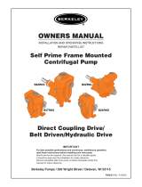
Pump Nomenclature 18
Electric Motor Drive—with fixed seal plate
Mechanical Seal
• Electricmotornotshown.
• Drawingshowstypicalmotordrivepumpwith
a mechanical shaft seal. Parts on some models
will vary slightly.
5530 0212
Seal Retaining
Ring
Mechanical
Seal
Motor
Bracket
T
r
u
a
r
c
Clack
Weight
Rubber Clack
(Check Valve)
Clack
Washer
Suction
Cover
Pump Case
(Volute)
Impeller
Case Gasket
Impeller
Lock Nut

Troubleshooting 19
Cause Corrective Action
Electrical
A.Novoltageinpowersystem.
Check phase-to-phase on line side of starter contactor.
Check circuit breaker or fuses.
B.Novoltageononephase(ThreePhaseunits).
Check phase voltage on line side of starter contactor. Isolate open circuit (circuit breaker, fuse,
broken connections, etc.)
C.Lowvoltageatmotor.
Runningvoltageacrosseachlegofmotormustbe±10%ofnominalvoltageshownon
nameplate.
D.Motorleadsimproperlygroupedforvoltage. Refertoleadgroupingdiagramonmotornameplate.
E.Controlfailure. Check control device, starter contactor, H-O-A selector switch, etc., for malfunction.
F. Thermal overload switch open Check phase-to-phase on line side of starter contactor.
G.Installationfailure. Check motor or windings to ground with megohmmeter.
H. Open windings. Check leg-to-leg with ohmmeter.
I. Frequency variation. Checkfrequencyofpowersystem.Mustbelessthan5%variationfrommotornameplaterating.
Mechanical
A. Flow through pump completely or partially obstructed. Locateandremoveobstruction.Refertorepairinstructionsfordisassembly.
B. Wrong direction of rotation.
Reverserotationofthreephasemotorbyinterchanginganytwoleads.Seemanufacturer’s
instructions for reversing single phase motor.
C. Pump lost prime. Reprime.Inspectsuctionsystemforairleaks.
D. Internal leakage. Checkimpellerforwearofcontrolledclearances(SeeRepairInstructions).
E.Looseparts Inspect.Repair.
F. Stuffing box not properly adjusted Adjust gland.
System
A. Pressure required by system at design flow rate exceeds
pressure rating of pump.
Compare pump pressure and flow rate against pump characteristic curve. Check for closed or
partially closed valve in discharge piping system.
Reducesystempressurerequirement.Increasepressurecapabilityofpump.
B. Obstruction in suction piping Locateandremoveobstruction.
C. Pressure rating of pump exceeds pressure requirement
of system at design flow rate.
Compare pump pressure and flow rate against pump characteristic curve.
Inspect discharge piping system for breaks, leaks, open by-pass valves, etc. If necessary, reduce
flow rate by partially closing discharge valve.
Symptom
Probable Cause
Electrical Mechanical System
A B C D E F G H I A B C D E F A B C
Pump runs, but no water delivered X X X X
Notenoughwaterdelivered X X X X X X X X
Notenoughpressure X X X X X X X X
Excessivevibration X X X X X X
Abnormal noise X X X X X X X
Pump stops X X X X X X X X
Overheating X X X X X X X X X

/