en Important safety information
4
(Important safety
information
Impor t ant saf et y informat i on
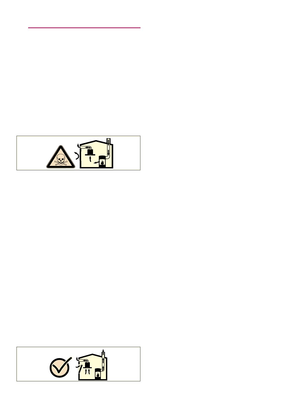
:Warning – Danger of suffocation!
Packaging material is dangerous to children.
Never allow children to play with packaging
material.
:Warning – Danger of death!
Risk of poisoning from flue gases that are
drawn back in.
Always ensure adequate fresh air in the room
if the appliance is being operated in exhaust
air mode at the same time as room air-
dependent heat-producing appliance is being
operated.
Room air-dependent heat-producing
appliances (e.g. gas, oil, wood or coal-
operated heaters, continuous flow heaters or
water heaters) obtain combustion air from the
room in which they are installed and discharge
the exhaust gases into the open air through an
exhaust gas system (e.g. a chimney).
In combination with an activated vapour
extractor hood, room air is extracted from the
kitchen and neighbouring rooms - a partial
vacuum is produced if not enough fresh air is
supplied. Toxic gases from the chimney or the
extraction shaft are sucked back into the living
space.
■ Adequate incoming air must therefore
always be ensured.
■ An incoming/exhaust air wall box alone will
not ensure compliance with the limit.
Safe operation is possible only when the
partial vacuum in the place where the heat-
producing appliance is installed does not
exceed 4 Pa (0.04 mbar). This can be
achieved when the air needed for combustion
is able to enter through openings that cannot
be sealed, for example in doors, windows,
incoming/exhaust air wall boxes or by other
technical means.
In any case, consult your responsible Master
Chimney Sweep. He is able to assess the
house's entire ventilation setup and will
suggest the suitable ventilation measures to
you.
Unrestricted operation is possible if the vapour
extractor hood is operated exclusively in the
circulating-air mode.
:Warning – Risk of fire!
■ Grease deposits in the grease filter may
catch fire.
Clean the grease filter at least every
2 months.
Never operate the appliance without the
grease filter.
Risk of fire!
■ Grease deposits in the grease filter may
catch fire. Never work with naked flames
close to the appliance (e.g. flambéing). Do
not install the appliance near a heat-
producing appliance for solid fuel (e.g.
wood or coal) unless a closed, non-
removable cover is available. There must
be no flying sparks.
Risk of fire!
■ Hot oil and fat can ignite very quickly. Never
leave hot fat or oil unattended. Never use
water to put out burning oil or fat. Switch off
the hotplate. Extinguish flames carefully
using a lid, fire blanket or something similar.
Risk of fire!
■ When gas burners are in operation without
any cookware placed on them, they can
build up a lot of heat. A ventilation
appliance installed above the cooker may
become damaged or catch fire. Only
operate the gas burners with cookware on
them.
Risk of fire!
■ Operating several gas burners at the same
time gives rise to a great deal of heat. A
ventilation appliance installed above the
cooker may become damaged or catch fire.
Never operate two gas burners
simultaneously on the highest flame for
longer than 15 minutes. One large burner of
more than 5 kW (wok) is equivalent to the
power of two gas burners.
:Warning – Risk of burns!
The accessible parts become very hot when in
operation. Never touch hot parts. Keep
children at a safe distance.


