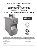
Burnham 205 Installation guide

Type
Installation guide
103698-05 - 2/16
Price - $5.00
INSTALLATION, OPERATING AND
SERVICE INSTRUCTIONS FOR
Series 2
®
Gas - Fired Boiler
9700609
For service or repairs to boiler, call your heating contractor. When seeking information on boiler, provide
Boiler Model Number and Serial Number as shown on Rating Label.
Model Number
2
Boiler Serial Number Installation Date
Heating Contractor Phone Number
Address
2
NOTE: The equipment shall be installed in accordance with those installation regulations in force in the area where the
installation is to be made. These shall be carefully followed in all cases. Authorities having jurisdiction shall be consulted before
installations are made.
All wiring on boilers installed in the USA shall be made in accordance with the National Electrical Code and/or local regulations.
All wiring on boilers installed in Canada shall be made in accordance with the Canadian Electrical Code and/or local regulations.
The City of New York requires a Licensed Master Plumber supervise the installation of this product.
The Massachusetts Board of Plumbers and Gas Fitters has approved the Series 2 boiler. See the Massachusetts Board of Plumbers
and Gas Fitters website, http://license.reg.state.ma.us/pubLic/pl_products/pb_pre_form.asp for the latest Approval Code or
ask your local Sales Representative.
The Commonwealth of Massachusetts requires this product to be installed by a Licensed Plumber or Gas Fitter.
The following dened terms are used throughout this manual to bring attention to the presence of hazards of various risk levels, or
to important information concerning the life of the product.
DANGER
Indicates presence of a hazard which will cause
severe personal injury, death or substantial
property damage if ignored.
CAUTION
Indicates presence of a hazard which will or can
cause minor personal injury or property damage
if ignored.
WARNING
Indicates presence of a hazard which can cause
severe personal injury, death or substantial
property damage if ignored.
NOTICE
Indicates special instructions on installation,
operation, or maintenance which are important
but not related to personal injury hazards.
DANGER
DO NOT store or use gasoline or other ammable vapors or liquids in the vicinity of this or any other appliance.
If you smell gas vapors, DO NOT try to operate any appliance - DO NOT touch any electrical switch or use
any phone in the building. Immediately, call the gas supplier from a remotely located phone. Follow the gas
suppliers instructions or if the supplier is unavailable, contact the re department.
3
WARNING
This boiler requires regular maintenance and service to operate safely. Follow the instructions contained
in this manual.
Improper installation, adjustment, alteration, service or maintenance can cause property damage, personal
injury or loss of life. Read and understand the entire manual before attempting installation, start-up
operation, or service. Installation and service must be performed only by an experienced, skilled and
knowledgeable installer or service agency
This boiler must be properly vented.
This boiler needs fresh air for safe operation and must be installed so there are provisions for adequate
combustion and ventilation air.
The interior of the venting system must be inspected and cleaned before the start of the heating season
and should be inspected periodically throughout the heating season for any obstructions. A clean and
unobstructed venting system is necessary to allow noxious fumes that could cause injury or loss of life
to vent safely and will contribute toward maintaining the boilers efciency.
Installation is not complete unless a pressure relief valve is installed into the tapping located on top of
boiler. - See the Boiler Water Piping Section of this manual for details.
This boiler is supplied with safety devices which may cause the boiler to shut down and not re-start
without service. If damage due to frozen pipes is a possibility, the heating system should not be left
unattended in cold weather; or appropriate safeguards and alarms should be installed on the heating
system to prevent damage if the boiler is inoperative.
This boiler contains very hot water under high pressure. Do not unscrew any pipe ttings nor attempt
to disconnect any components of this boiler without positively assuring the water is cool and has no
pressure. Always wear protective clothing and equipment when installing, starting up or servicing this
boiler to prevent scald injuries. Do not rely on the pressure and temperature gauges to determine the
temperature and pressure of the boiler. This boiler contains components which become very hot when
the boiler is operating. Do not touch any components unless they are cool.
Boiler materials of construction, products of combustion and the fuel contain alumina, silica, heavy metals,
carbon monoxide, nitrogen oxides, aldehydes and/or other toxic or harmful substances which can cause
death or serious injury and which are known to the state of California to cause cancer, birth defects and
other reproductive harm. Always use proper safety clothing, respirators and equipment when servicing
or working nearby the boiler.
Failure to follow all instructions in the proper order can cause personal injury or death. Read all instructions,
including all those contained in component manufacturers manuals which are provided with the boiler
before installing, starting up, operating, maintaining or servicing.
All cover plates, enclosures and guards must be in place at all times.
NOTICE
This boiler has a limited warranty, a copy of which is included with this boiler. It is the responsibility of
the installing contractor to see that all controls are correctly installed and are operating properly when the
installation is complete.
4
TABLE OF CONTENTS
I. Product Description, Specications and Dimensional Data...................... 4
II. Pre-Installation & Boiler Mounting ............................................................ 6
III. Gas Piping................................................................................................. 8
IV. Boiler Water Piping.................................................................................... 9
V. Venting....................................................................................................... 14
VI. Electrical.................................................................................................... 18
VII. System Start-up and Checkout.................................................................. 22
VIII. Operation................................................................................................... 26
IX. Service and Maintenance.......................................................................... 30
X. Troubleshooting........................................................................................ 34
XI. Repair Parts ............................................................................................. 39
Appendix A - Figures............................................................................................. 56
Appendix B - Tables............................................................................................. 58
The Series 2 boilers are low pressure cast iron gas
red hot water boilers designed for use in closed hot
water heating systems. These boilers are Category
I draft hood equipped appliances, which must be
I. PRODUCT DESCRIPTION, SPECIFICATIONS AND DIMENSIONAL DATA
vented by natural draft using a lined masonry or
listed metal chimney system. An adequate supply
of air for combustion, ventilation and dilution of
ue gases must be available in the boiler room.
5
I. PRODUCT DESCRIPTION, SPECIFICATIONS AND DIMENSIONAL DATA
(CONTINUED)
Figure 1: Line Drawing
Boiler
Model
Number
Dimensions [Inches] Gas
Connection
For Automatic
Gas Valve
Water
Content
[gallons]
Recommended
Vent Size
[2]
Approx.
Shipping
Weight
[lb.]
A B C D E F G
202 18-3/4 10-3/4 6-3/8 4 45-5/8 8-1/2 10 [1] 1/2 2.5 3" dia. 212
202X 20 12 6 4 45-5/8 8-1/2 4-3/4 1/2 3.2 4” dia. 262
203 20 12 6 4 45-5/8 8-1/2 4-3/4 1/2 3.2 4” dia. 262
204 23-1/4 15-1/4 7-5/8 5 47-1/8 9-1/8 4-3/4 1/2 4 5" dia. 306
205 26-1/2 18-1/2 9-1/4 6 48-1/2 9-3/4 5-1/4 1/2 4.7 6" dia. 354
206 29-3/4 21-3/4 10-7/8 6 48-1/2 9-3/4 5-1/4 1/2 5.5 6" dia. 414
207 33 25 12-1/2 7 50-1/8 10-3/8 6-5/8 3/4 6.2 7" dia. 458
208 36-1/4 28-1/4 14-1/8 7 50-1/8 10-3/8 6-5/8 3/4 7 7" dia. 514
209 39-1/2 31-1/2 15-3/4 8 52 11 7-1/4 3/4 7.7 8" dia. 550
210 42-3/4 34-3/4 17-3/8 8 52 11 7-1/4 3/4 8.5 8" dia. 608
[1] 202 only. Dimension 'G' includes allowance for 4" x 3" reducer furnished with boiler. See Figure 12.
[2] Refer to the National Fuel Gas Code for equivalent areas of circular and rectangular ue linings.
Maximum Allowable Working Pressure, Water - 50 PSI
Safety Relief Valve Pressure, Water - 30 PSI shipped from factory (std.); 50 PSI - optional
Table 1: Dimensions
6
II. PRE-INSTALLATION AND BOILER MOUNTING
WARNING
If you do not follow these instructions exactly,
a re or explosion may result causing property
damage or personal injury.
A. INSPECT SHIPMENT carefully for any signs of
damage. All equipment is carefully manufactured,
inspected and packed. Our responsibility ceases upon
delivery of Boiler to the carrier in good condition. Any
claims for damage or shortage in shipment must be led
immediately against the carrier by the consignee. No
claims for variances or shortages will be allowed by
Boiler Manufacturer unless presented within sixty (60)
days after receipt of equipment.
B. BOILER INSTALLATION must conform to the
requirements of the authority having jurisdiction, or in
the absence of such requirements, to:
U.S.A. - National Fuel Gas Code, ANSI Z223.1/
NFPA 54.
CANADA - Natural and Propane Installation Code,
CAN/CSA B149.1.
Where required by authority having jurisdiction,
installation must conform to Standard for Controls and
Safety Devices for Automatically Fired Boilers, ANSI/
ASME CSD-1.
C. These Gas Boilers are DESIGN CERTIFIED FOR
INSTALLATION ON COMBUSTIBLE FLOORING.
DO NOT INSTALL THESE BOILERS ON
CARPETING.
NOTICE
Do not drop boiler. Do not bump boiler jacket
against oor.
D. LOCATE BOILER in front of or behind installation
position before removing Crate. Locate on a level oor
as close to chimney as possible. For basement
installations, provide a solid base such as concrete, if
oor is not level or if water may be encountered on
oor around Boiler.
The boiler shall be installed such that the gas ignition
system components are protected from water (dripping,
spraying, rain, etc.) during boiler operation and service
(circulator replacement, control replacement, etc.).
DANGER
Do not install boiler where gasoline or other
ammable vapors or liquids, or sources of
hydrocarbons (i.e. bleaches, cleaners, chemicals,
sprays, paint removers, fabric softeners, etc.) are
used or stored.
CAUTION
Avoid operating this boiler in an environment
where saw dust, loose insulation bers, dry wall
dust, etc. are present. If boiler is operated under
these conditions, the burner interior and ports
must be cleaned and inspected daily to insure
proper operation.
E. REMOVE CRATE -
1. Remove all crate fasteners. Lift off outside
container.
2. Remove all screws and brackets securing boiler to
skid.
3. Save two of the wooden slats from the container
sleeve for use in Steps 4, 5 and 6.
4. Tilt the boiler to one side and slide a wooden slat
under the two raised feet.
5. Tilt the boiler to the other side and slide another
wooden slat under the two raised feet.
6. Slide the boiler forward or backward off the skid
using the two wooden slats as runners.
F. Move boiler to permanent position.
G. PROVIDE CLEARANCE and AIR for
COMBUSTION and VENTILATION.
WARNING
Adequate combustion and ventilation air must be
provided to assure proper combustion.
1. CLEARANCES
a. ALL INSTALLATIONS - Practical service
clearances must be considered (see Figure 2). A
minimum of 24" (6.0cm) from the left side and
front jacket panels is recommended for servicing
but may be reduced to minimum shown in
Figure 2. Subject to boiler and system piping,
right side clearance may be reduced to 1"
(2.5cm) if left side clearance is increased to 9"
(22.9cm).
b. ALCOVE INSTALLATIONS - An alcove is
considered a closet as shown in Figure 2 less
front. Height clearance may be reduced to 27"
(68.6cm).
c. UNCONFINED SPACE (see denition,
paragraph (2) below) - Height clearance may be
reduced to 27" (68.6cm).
2. PROVIDE COMBUSTION AND VENTILATION
AIR in accordance with the section "Air for
Combustion and Ventilation", of the National Fuel
Gas Code, ANSI Z223.1/NFPA, or Sections 8.2, 8.3,
7
or 8.4 of Natural Gas and Propane Installation Code,
CAN/CSA B149.1, or applicable provisions of local
building codes.
a. CLOSET INSTALLATIONS (conned space) in a
building of other than unusually tight construction
(see denition below), provide combustion and
ventilation air as shown in Figure 2.
b. Installations other than closet in paragraph (a) :
i. Determine volume of space (boiler room).
Rooms communicating directly with space
(through openings not furnished with doors)
are considered part of space.
Volume [ft³](m
3
) = Length [ft](m) x Width [ft]
(m) x Height [ft](m)
ii. Determine Total Input of all appliances in
space. Round result to nearest 1,000 Btu per
hour (Btuh).
iii. Determine type of space. Divide Volume by
Total Input.
• If result is greater than or equal to 50 ft³
(1.4m3) per 1,000 Btuh, space is considered
an unconnedspace.
• If result is less than 50 ft³ (1.4m3) per 1,000
Btuh, space is considered a connedspace.
iv. Determine building type. A building of
unusually tight construction has the following
characteristics:
Figure 2: Minimum Clearances
• Walls and ceiling exposed to outside
atmosphere have a continuous water vapor
retarder with a rating of 1 perm or less with
openings gasketed and sealed, and
• Weather-stripping has been added on
openable windows and doors, and
• Caulking or sealants applied in joints around
window and door frames, between sole
plates and oors, between wall-ceiling joints,
between wall panels, at plumbing and
electrical penetrations, and at other openings.
v. For boiler located in a building of other than
unusually tight construction, adequate
combustion and ventilation air is normally
provided by fresh air inltration through
cracks around windows and doors.
vi. For boiler located in building of unusually
tight construction, provide outdoor air through
two permanent openings which communicate
directly or by duct with the outdoors or spaces
(crawl or attic) freely communicating with the
outdoors. Locate one opening within 12 inches
(30.5cm) of top of space. Locate remaining
opening within 12 inches (30.5cm) of bottom
of space. Minimum dimension of air opening
is 3 inches (7.6cm). Size each opening per
following:
• Direct communication with outdoors.
Minimum free area of 1 square inch (6.5cm
2
)
per 4,000 Btu per hour input of all
equipment in space.
• Vertical ducts. Minimum free area of 1
square inch (6.5cm
2
) per 4,000 Btu per hour
input of all equipment in space. Duct
cross-sectional area shall be same as opening
free area.
• Horizontal ducts. Minimum free area of 1
square inch (6.5cm
2
) per 2,000 Btu per hour
input of all equipment in space. Duct
cross-sectional area shall be same as opening
free area.
vii. Ventilation Duct Louvers and Grilles. Equip
outside openings with louvers to prevent
entrance of rain and snow, and screens to
prevent entrance of insects and rodents.
Louvers and grilles must be xed in open
position or interlocked with equipment to open
automatically before burner operation. Screens
must not be smaller than ¼ inch mesh.
Consider the blocking effect of louvers, grilles
and screens when calculating the opening size
to provide the required free area. If free area of
louver or grille is not known, assume wood
louvers have 20-25 percent free area and metal
louvers and grilles have 60-75 percent free
area.
II. PRE-INSTALLATION AND BOILER MOUNTING (continued)
BOILER
MODEL
‘W’
202 10¾” (27.3cm)
202X 12” (30.5cm)
203 12” (30.5cm)
204 15¼” (38.7cm)
205 18½” (47.0cm)
206 21¾” (55.2cm)
207 25” (63.5cm)
208 28¼” (71.8cm)
209 31½” (80.0cm)
210 34¾” (88.3cm)
8
III. GAS PIPING
A. CONNECT GAS SERVICE from Meter to gas control
assembly in accordance with Local Piping Codes and
requirements of Gas Company. They may require
piping of larger size than Control Assembly
Connection, especially if run from meter is long or
includes several elbows. See Figure 1 for size of Gas
Connection to gas control assembly.
This piping is to be supplied by the installer and must
include a trap, a ground joint union and a manual
shutoff valve upstream of the gas control assembly
outside of the jacket when codes require, see Figure 3.
A pipe thread compound resistant to the action of
liqueed petroleum gases should be applied to all
threaded joints in the gas piping. Pressure testing of the
Gas Supply Piping Boiler and its connections is
required before placing the boiler in operation.
The boiler and shutoff valve must be disconnected from
the gas supply piping system during any pressure
testing at pressures greater than ½ psig (3.5kPa).
The boiler must be isolated from the gas supply piping
system by closing its individual manual shutoff valve
during any pressure testing of the gas supply piping
system at pressures equal to or less than ½ psig
(3.5kPa).
RECOMMENDED SIZING OF GAS SUPPLY
PIPING TO BOILER FOR NATURAL GAS - shall
be such as to provide the required supply of gas without
undue loss of pressure between meter and the boiler.
Gas supply piping should be sized in accordance with
the Tables 2, 3 and 4. The following shall be taken into
account:
1. Allowable loss of pressure to assure a burner
manifold pressure of 3½" (8.9cm) water for natural
gas.
2. Supply of gas to be provided in cubic feet.
3. Length of piping and number of ttings.
4. Specic gravity of gas.
5. Correction factor for specic gravity.
Table 2: Maximum Capacity of Schedule 40 Pipe in CFH for Natural Gas Pressures of ½ psig or Less
Length
[Feet]
0.3 Inch w.c. Pressure Drop 0.5 Inch w.c. Pressure Drop
½ ¾ 1 ½ ¾ 1
10 132 278 520 1,050 175 360 680 1,400
20 92 190 350 730 120 250 465 950
30 73 152 285 590 97 200 375 770
40 63 130 245 500 82 170 320 660
50 56 115 215 440 73 151 285 580
60 50 105 195 400 66 138 260 530
70 46 96 180 370 61 125 240 490
80 43 90 170 350 57 118 220 460
90 40 84 160 320 53 110 205 430
100 38 79 150 305 50 103 195 400
Table 3: Equivalent Length of Fittings
Fitting
Nominal Pipe Size
½ ¾ 1
45° Ell 0.7 1 1.2 1.6
90° Ell 1.6 2.1 2.6 3.5
Tee (As Elbow) 3.1 4.1 5.2 6.9
Table 4: Specic Gravity Correction Factors for
Natural Gas
Specic
Gravity
Correction
Factor
Specic
Gravity
Correction
Factor
0.50 1.10 1.30 1.07
0.55 1.04 1.40 1.04
0.60 1.00 1.50 1.00
0.65 0.96 1.60 0.97
0.70 0.93 1.70 0.94
0.75 0.90 --- ---
0.80 0.87 --- ---
Figure 3: Recommended Gas Piping
9
A. BOILER WATER PIPING
CAUTION
Failure to properly pipe boiler may result in
improper operation and damage to boiler or
building.
1. CLEARANCES - Hot water pipes do not require
clearance from combustible construction.
2. Install drain valve and safety relief valve as shown
in Figures 1 and 4. Note - Safety relief valve must
be in vertical position.
3. Pipe safety relief valve discharge to oor.
WARNING
Safety relief valve discharge piping must be
piped near oor to eliminate potential of severe
burns. Do not pipe in any area where freezing
could occur. Do not install any shut-off valves.
4. Install Temperature and Pressure gauge externally in
boiler supply piping. All required components are
included at factory supplied Miscellaneous Parts
Bag (P/N 103669-01). See Figure 4 ‘Near Boiler
Piping’.
5. Install circulator with anges, gaskets and bolts and
circulator harness provided.
6. For recommended water piping, see Figures 5 and 6.
Also, consult Residential Hydronic Heating
Installation and Design I=B=R Guide.
7. If this boiler is used in connection with refrigeration
systems, the boiler must be installed so that the
chilled medium is piped in parallel with the heating
boiler using appropriate valves to prevent the chilled
medium from entering the boiler, see Figure 7. Also
consult Residential Hydronic Heating Installation
and Design I=B=R Guide.
If this Boiler is connected to heating coils located in
air handling units where they may be exposed to
refrigerated air, the boiler piping must be equipped
with ow control valves to prevent gravity
circulation of boiler water during the operation of
the cooling system.
8. Use a boiler bypass if the boiler is to be operated in
a system which has a large volume or excessive
radiation where low boiler water temperatures may
be encountered (i.e. converted gravity circulation
system, etc.).
Install a pipe tee at the boiler return along with a
second tee in the supply piping as shown in Figures
5 and 6. The bypass should be the same size as the
supply and return lines with valves located in the
IV. BOILER WATER PIPING
Figure 4: Near Boiler Piping
bypass and supply outlet as illustrated in Figures 5
and 6 in order to regulate water ow to maintain
higher boiler water temperatures.
Set the boiler supply valve to fully open position,
and the boiler bypass valve to half throttle. Operate
the boiler and adjust the bypass valve to achieve
180°F to 200°F supply water temperature by closing
the bypass valve to decrease supply temperature or
opening the bypass valve to increase water
temperature. If the bypass valve is fully opened and
the boiler water temperature is still below 180°F,
slowly begin closing the boiler supply valve to
achieve 180°F to 200°F supply water temperature.
Caution: Never fully close the boiler supply valve.
10. If it is required to perform a long term pressure test
of the hydronic system, the boiler should rst be
isolated to avoid a pressure loss due to the escape of
air trapped in the boiler.
To perform a long term pressure test including the
boiler, ALL trapped air must rst be removed from
the boiler.
A loss of pressure during such a test, with no visible
water leakage, is an indication that the boiler
contained trapped air.
11. OXYGEN CORROSION:
Oxygen contamination of the boiler water will cause
corrosion of the iron and steel boiler components,
which can lead to failure. As such, any system must
be designed to prevent oxygen absorption in the rst
place or prevent it from reaching the boiler.
Problems caused by oxygen contamination of boiler
water are not covered by U.S. Boiler Company's
standard warranty.
10
IV. BOILER WATER PIPING (continued)
Figure 5: Recommended Water Piping for Zone Valve Zoned Heating Systems
11
IV. BOILER WATER PIPING (continued)
Figure 6: Recommended Water Piping for Circulator Zoned Heating Systems
12
IV. BOILER WATER PIPING (continued)
There are many possible causes of oxygen
contamination such as:
a. Addition of excessive make-up water as a result
of system leaks.
b. Absorption through open tanks and ttings.
c. Oxygen permeable materials in the distribution
system.
In order to insure long product life, oxygen
sources should be eliminated. This can be
accomplished by taking the following measures:
a. Repairing system leaks to eliminate the need for
addition of make-up water.
b. Eliminating open tanks from the system.
c. Eliminating and/or repairing ttings which allow
oxygen absorption.
d. Use of non-permeable materials in the
distribution system.
e. Isolating the boiler from the system water by
installing a heat exchanger.
B. OPTIONAL PROBE LWCO INSTALLATION
WARNING
DO NOT ATTEMPT to cut factory wires to
install an aftermarket Low Water Cut Off
(LWCO). Only use connections specically
identied for Low Water Cut Off.
In all cases, follow the Low Water Cut Off
(LWCO) manufacturer’s instructions.
1. A low water cutoff is required to protect a gas-red
hot water boiler when any connected heat distributor
(radiation) is installed below the top of the hot water
boiler (i.e. baseboard on the same oor level as the
boiler). In addition, some jurisdictions require the
use of a LWCO with a hot water boiler as a
redundant safety control.
It is recommended that the LWCO control is
installed above the boiler to provide the highest
level of protection. However, where the LWCO
control is approved by the LWCO control
manufacturer for installation in a high boiler tapping
of a water boiler, the use of the listed LWCO control
is permitted when it is installed according to the
LWCO manufacturer's instructions.
2. The recommended location for a LWCO on gas hot
water boilers is above the boiler, in the supply
piping. The minimum safe water level of a water
boiler is at the uppermost top of the boiler; that is, it
must be full of water to operate safely.
3. Typically, in residential applications, a probe type
LWCO is used instead of a oat type, due to their
relative costs and the simplicity of piping for a
probe LWCO.
Figure 7: Recommended Piping for Combination
Heating & Cooling (Refrigeration) Systems
Figure 8: Recommended Probe LWCO Location
13
4. Piping and ttings required to install LWCO are
eld supplied.
5. When constructing a piping tree to install LWCO
select ttings (tees, elbows etc) and nipples to have
the same size (NPT) as boiler supply connection. At
minimum, 1-1/4” tee with ¾” branch outlet is
required to connect the probe LWCO to the supply
piping. See Figure 8 for location and piping of the
LWCO. DO NOT REDUCE THE SIZE OF
NEAR BOILER SUPPLY FITTINGS AND
NIPPLES.
6. Installation of manual shutoff valve located above
the LWCO and the boiler is recommended to allow
servicing. Thus LWCO probe can be removed for
inspection without draining the heating system. An
annual inspection of the probe is recommended.
7. The presence of water covering properly installed
LWCO probe will cause the normally open contact
of the LWCO to close, thus providing continuity of
the 24 VAC service to the boiler gas valve. When
water level drops below probe, LWCO contact
opens up breaking 24V supply to gas valve and
preventing the boiler to re.
8. 2012 compliant Series 2 gas hot water boilers have a
“plug-in” provision in factory wiring that will accept
optional 24VAC probe LWCO harness connector.
The optional LWCO kit (P/N 104083-01) includes
24VAC probe LWCO, Harness and Instructions
addressing piping, wiring and testing after
installation. See Figure 13 for wiring of the LWCO.
IV. BOILER WATER PIPING (continued)
Figure 9: Recommended Auxiliary Limit Location
C. OPTIONAL AUXILIARY LIMIT INSTALLATION
1. Some jurisdictions may require the use of an
Auxiliary Limit control with a hot water boiler as a
redundant safety control.
2. The recommended location for an Auxiliary Limit
on gas hot water boilers is in the supply piping. See
Figure 9 for recommended location.
3. Piping and ttings required to install an Auxiliary
Limit are eld supplied.
4. When constructing a piping tree to install an
Auxiliary Limit select ttings (tees, elbows etc) and
nipples to have the same size (NPT) as boiler supply
connection. At minimum, 1-1/4” tee with 1/2”
branch outlet is required to install the limit well into
the supply piping. See Figure 9. DO NOT
REDUCE THE SIZE OF NEAR BOILER
SUPPLY FITTINGS AND NIPPLES.
5. When boiler water temperature reaches or exceeds
Auxiliary Limit setting, the limit normally closed
contact will open, thus interrupting the 24 VAC
service to the boiler gas valve. When boiler water
temperature drops below limit differential, limit
contact closes restoring 24V supply to gas valve and
allowing the boiler to re.
6. Gas hot water boilers equipped with Intelligent
Hydronic Control have a “plug-in” provision in
factory wiring that will accept optional 24VAC
Auxiliary Limit harness connector. The optional
Auxiliary Limit kit (P/N 103696-01) includes
24VAC Auxiliary Limit, Well, Harness and
Instructions addressing wiring and testing after
installation.
14
Figure 10: Blocked Vent Switch
Installation Diagram
A. INSTALL DRAFT HOOD without modication on
outlet of ue collector (See Figure 1). Secure with sheet
metal screws.
WARNING
Do not alter boiler draft hood or place any
obstruction or non-approved damper in the
breeching or vent system. Flue gas spillage can
occur. ETL certication will become void.
B. INSTALL BLOCKED VENT SWITCH
The blocked vent switch assembly shipped taped to the
top of the boiler includes a power cord and a switch
attached to a mounting bracket. The mounting bracket
has a three tooth staggered comb stamping at one end
with a #10 sheet metal screw in the center tooth.
1. Untape the blocked vent switch assembly from the
top of the boiler and uncoil the power cord.
2. Blocked vent switch power cord (black and black
with white stripe wires) is attached to vent damper
harness with wire ties. The length of the cord is
sufcient to reach the blocked vent switch installed
at the left side of the draft hood skirt (see Figure 10).
However, if required, use at blade screwdriver to
dislodge black strain relief bushing, securing the
harness to boiler left side jacket, to adjust the length
as needed.
3. Position the mounting bracket (with switch attached)
onto the lower edge of the draft hood skirt by
locating the center tooth (with the #10 sheet metal
screw) on the outside and the other two teeth inside
the draft hood skirt. See Figure 10.
4. Slide the mounting bracket up tight against the
lower edge of the draft hood skirt, so that the #10
sheet metal screw is above the skirt's stiffening rib.
5. Secure the bracket in this position by tightening the
#10 sheet metal screw against the outer surface of
the draft hood skirt.
6. If required, reinsert the excess power cord through
the jacket side panel hole to take the slack out of the
wires running to up to the switch and vent damper.
7. Reposition the strain relief bushing around the
power cord at the jacket side panel, pinch the two
halves of the bushing together, and snap it back into
the hole in the jacket side panel to secure the power
cord to the jacket.
8. Be sure the power cord, mounting bracket, and
switch are secure and located as shown in Figure 10.
V. VENTING
WARNING
Failure to properly install and use this Blocked
Vent Switch may result in property damage,
personal injury or loss of life.
C. INSTALL VENT DAMPER
OPEN THE VENT DAMPER CARTON and remove
the Installation Instructions. READ THE
INSTALLATION INSTRUCTIONS THOROUGHLY
before proceeding.
The automatic gas control valve supplied on each
Series
2
®
boiler provides the redundancy referenced in
the vent damper Installation Instructions.
CAUTION
Do not use one vent damper to control two heating
appliances.
15
Figure 11: Plug-in Damper Installation
1. The vent damper must be the same size as the outlet
of the Draft Hood supplied with the boiler (see
Figure 1). Unpack the damper carefully - DO NOT
FORCE IT CLOSED! Forcing the damper may
damage the gear train and void the warranty.
2. Mount the vent damper assembly after the draft
hood, as close to the draft hood as practicable
without modication to the draft hood or vent
damper. (Refer to Figure 11 and to instructions
packed with the vent damper for specic
instructions). This is a must for the wiring harness to
t and the damper position indicator to be visible to
the users.
NOTICE
Provide adequate clearance for servicing.
WARNING
Provide 6" (15.2cm) minimum clearance between
damper and combustible construction.
3. Plug the factory harness vent damper connector into
damper motor polarized receptacle and secure the
harness to the damper motor bracket with provided
strain relief bushing.
DANGER
Inspect existing chimney before installing boiler.
Failure to clean or replace perforated pipe or tile
lining will cause severe injury or death.
D. INSTALL VENT CONNECTOR
1. Size 202 only - Install provided 4" x 3" vent reducer
into vent damper outlet, then, install vent connector
from reducer outlet to chimney.
2. All other sizes - Install vent connector from vent
damper outlet to chimney.
3. Install vent system in accordance with local building
codes; or local authority having jurisdiction; or
"Venting of Equipment", of the National Fuel Gas
Code, ANSI Z223.1/NFPA 54, or "Venting Systems
and Air Supply for Appliances", of the Natural Gas
and Propane Installation Code, CAN/CSA B149.1.
Install any of the following for this Series 2 Category I,
draft hood equipped appliance:
a. Type B or Type L gas vent. Install in accordance
with listing and manufacturer's instructions.
b. Masonry or metal chimney. Build and install in
accordance with local building codes; or local
authority having jurisdiction; or Standard for
Chimneys, Fireplaces, Vents, and Solid Fuel
Burning Appliances, ANSI/NFPA 211 and/or
National Building Code of Canada.
Masonry chimney must be lined with approved
clay ue lining or listed chimney lining system.
c. Single wall metal vent. Allowed by ANSI
Z223.1/NFPA 54 under very restrictive
conditions.
d. Do not use cellular core PVC (ASTM F891),
cellular core CPVC, or Radel
®
(polyphenolsulfone).
e. Do not cover non-metallic vent pipe and ttings
with thermal insulation. Note: Non-metallic
vent cannot be used with this boiler.
V. VENTING (continued)
16
Figure 12: Typical Vent Installation
4. Do not connect into same leg of chimney serving an
open replace.
5. Inspect chimney for obstructions or restrictions and
remove. Clean chimney if necessary.
6. Vent pipe to chimney must not be smaller than outlet
on draft hood or damper. Although single wall vent
pipe may be used, Type B is recommended. The
venting system must be arranged so that only the
boiler is served by the damper device. Installation
per paragraph (C) complies with this provision.
Exception: National Fuel Gas Code, ANSI
Z223.1/ NFPA 54, and Natural Gas and Propane
Installation Code, CAN/CSA B149.1, allow vent
downsizing when vent size determined by their
Vent Sizing Tables is smaller than draft hood
outlet/vent damper. These codes require all of
the following:
(a) Total vent height (H) is at least 10 ft (3 m);
(b) Vent not reduced more than one table size;
and
(c) Draft hood outlet/vent damper is greater
than 4 in. (102 mm) in diameter (202, 202X
and 203 cannot use smaller vent size).
7. Where two or more appliances vent into a common
vent, the area of the common vent should at least
equal the area of the largest vent plus 50% of the
area in the additional vents. Do not connect the vent
of this appliance into any portion of mechanical
draft system operating under positive pressure.
8. Vent pipe should have the greatest possible initial
rise above the draft hood consistent with the head
room available and the required clearance from
adjacent combustible building structure. Vent Pipe
should be installed above the bottom of chimney to
prevent blockage.
V. VENTING (continued)
9. Slope horizontal portions of vent pipe upwards not
less than 1/4 in/ft (21 mm/m) from boiler to vent
terminal.
les chaudiêres de catégories I doivent présenter des
tronçons horizontaux dont la pente montante est d'au
moins 1/4 po par pied (21 mm/m) entre la chaudiêre
et l'évent.
10. Support horizontal portions of venting system to
prevent sagging. Use pipe straps, brackets or
hangers spaced 4 ft (1.2 m) or less.
Soutenez parties horizontales de ventilation pour
éviter l'affaisement. Utilisez des colliers de serrage,
des crochets on cintres espacées de 4 preds (1,2 m)
ou moins.
11. Vent pipe must be inserted into but not beyond
inside wall of chimney liner. Seal tight between vent
pipe and chimney.
12. Do not install non-listed (AGA, CGA, CSA, ETL or
UL) vent damper or other obstruction in vent pipe.
WARNING
E. IF AN EXISTING BOILER IS REMOVED -
When an existing boiler is removed from a common
venting system, the common venting system is likely to
be too large for proper venting of the appliances
remaining connected to it.
At the time of removal of an existing boiler, the
following steps shall be followed with each appliance
remaining connected to the common venting system
placed in operation, while the other appliances
remaining connected to the common venting system are
not in operation:
1. Seal any unused openings in the common venting
system.
2. Visually inspect the venting system for proper size
and horizontal pitch and determine there is no
blockage or restriction, leakage, corrosion, and other
deciencies which could cause an unsafe condition.
3. Insofar as is practical, close all building doors and
windows and all doors between the space in which
the appliances remaining connected to the common
venting system are located and other spaces of the
building. Turn on clothes dryers and any appliance
not connected to the common venting system. Turn
on any exhaust fans, such as range-hoods and
bathroom exhausts, so they will operate at maxi mum
speed. Do not operate a summer exhaust fan. Close
replace dampers.
4. Place in operation the appliance being inspected.
Follow the Lighting (or Operating) Instructions.
Adjust thermo stat so appliance will operate
continuously.
17
5. Test for spillage at the draft hood relief opening
after 5 minutes of main burner operation. Use the
ame of a match or candle, or smoke from a
cigarette, cigar or pipe.
6. After it has been determined that each appliance
remain ing connected to the common venting system
properly vents when tested as outlined above, return
doors, win dows, exhaust fans, replace dampers and
any other gas-burning appliance to their previous
condition of use.
7. Any improper operation of the common venting
system should be corrected so the installation
conforms with the National Fuel Gas Code, ANSI
Z223.1/NFPA 54, and/or the Natural Gas and
Propane Installation Code, CAN/CSA B149.1.
When resizing any portion of the common venting
system, the common venting system should be
resized to approach the minimum size as determined
using the appropriate tables in Appendix F in the
National Fuel Gas Code, ANSI Z223.1/NFPA 54,
and/or the Natural Gas and Propane Installation
Code, CAN/CSA B149.1.
Au moment du retrait d’une chaudière existante, les
mesures suivantes doivent être prises pour chaque
appareil toujours raccordé au système d’evacuation
commun et qui fonctionne alors que d’autres appareils
toujours raccordés au système d’évacuation ne
fonctionnent pas:
1. Sceller toutes les ouvertures non utilisées du
système d’évacuation.
2. Inspecter de façon visuelle le système d’évcuation
pour déterminer la grosseur et l’inclinaison
horizontale qui conviennent et s’assurer que le
système est exempt d’obstruction, d’étranglement,
de fuite, de corrosion et autres défaillances qui
pourraient présenter des risques.
V. VENTING (continued)
3. Dans la mesure du possible, fermer toutes les portes
et les fenêtres du bâtiment et toutes les portes entre
l’espace où les appareils toujours raccordés au
système d’évacuation sont installés et les autres
espaces du bâtiment. Mettre en marche les
sécheuses, tous les appareils non raccordés au
système d’évacuation commun et tous les
ventilateurs d’extraction comme les hottes de
cuisinière et les ventilateurs des salles de bain.
S’assurer que ces ventilateurs fonctionnent à la
vitesse maximale. Ne pas faire fonctionner les
ventilateurs d’été. Fermer les registres des
cheminées.
4. Mettre l’appareil inspecté en marche. Suivre les
instructions d’allumage. Régler le thermostat de
façon que l’appareil fonctionne de façon continue.
5. Faire fonctionner le brùleur principal pendant 5 min
ensuite, déterminer si le coupe-tirage déborde à
l’ouverture de décharge. Utiliser la amme d’une
allumette ou d’une chandelle ou la fumée d’une
cigarette, d’un cigare ou d’une pipe.
6. Une fois qu’il a été déterminé, selon la méthode
indiquée ci-dessus, que chaque appareil raccordé au
système d’évacuation est mis à l’air libre de façon
adéquate. Remettre les portes et les fenêtres, les
ventilateurs, les registres de cheminées et les
appareils au gaz à leur position originale.
7. Tout mauvais fonctionnement du système
d’évacuation commun devrat être corrigé de façon
que l’installation soit conforme au National Fuel
Gas Code, ANSI Z223.1/NFPA 54 et (ou) aux codes
d’installation CAN/CSA-B149.1. Si la grosseur
d’une section du système d’évacuation doit être
modiée, le système devrait être modié pour
respecter les valeurs minimales des tableaux
pertinents de l’appendice F du National Fuel Gas
Code, ANSI Z223.1/NFPA 54 et (ou) des codes
d’installation CAN/CSA-B149.1.
18
A. INSTALL A ROOM THERMOSTAT on an inside
wall about four feet above oor. Never install
thermostat on an outside wall or where it will be
inuenced by drafts, hot or cold water pipes, lighting
xtures, television, rays of the sun or near a replace.
Keep large furniture away from thermostat so there will
be free movement of room air around this control.
Heat Anticipator in Thermostat should be set to 0.6
amp. If system tends to overheat above the thermostat's
temperature setting, reduce heat anticipator setting by .1
or .2 amps. If system tends to short cycle without
reaching desired room temperature, increase heat
anticipator setting by .1 or .2 amps.
B. INSTALL ELECTRIC WIRING in accordance with
National Electric Code or the Canadian Electrical Code
and local regulations. See Figures 13 through 16 for
applicable wiring diagram. A separate electrical circuit
must be run from the main electrical service with an
over-current device/disconnect in the circuit. A service
switch is recommended and may be required by some
local jurisdictions. When installed, the boiler must be
electrically grounded in accordance with the
requirements of authority having jurisdiction or, in the
absence of such requirements, with the National
Electrical Code, ANSI/NFPA 70, and/or the Canadian
Electrical Code part 1, CSA C22.1 Electrical Code.
For zone valve wiring, a separate 24V transformer is
required rather than attempting to use the boiler
mounted control. Consult zone valve manufacturer for
assistance.
VI. ELECTRICAL
WARNING
The combined boiler and circulator amperage
must not exceed 15 amps.
Install over-current protection in accordance with
authority having jurisdiction or, in the absence of
such requirements, follow the National Electric
Code, NFPA 70, and/or CSA C22.1 Electrical
Code. Do not provide over-current protection
greater than 15 amperes.
C. Refer to Figures 13 and 14 for details on the internal
wiring.
19
Figure 13: Connection Wiring Diagram, Intelligent Hydronic Control
VI. ELECTRICAL (continued)
20
Figure 14: Ladder Wiring Diagram, Intelligent Hydronic Control
VI. ELECTRICAL (continued)
  • Page 1 1
  • Page 2 2
  • Page 3 3
  • Page 4 4
  • Page 5 5
  • Page 6 6
  • Page 7 7
  • Page 8 8
  • Page 9 9
  • Page 10 10
  • Page 11 11
  • Page 12 12
  • Page 13 13
  • Page 14 14
  • Page 15 15
  • Page 16 16
  • Page 17 17
  • Page 18 18
  • Page 19 19
  • Page 20 20
  • Page 21 21
  • Page 22 22
  • Page 23 23
  • Page 24 24
  • Page 25 25
  • Page 26 26
  • Page 27 27
  • Page 28 28
  • Page 29 29
  • Page 30 30
  • Page 31 31
  • Page 32 32
  • Page 33 33
  • Page 34 34
  • Page 35 35
  • Page 36 36
  • Page 37 37
  • Page 38 38
  • Page 39 39
  • Page 40 40
  • Page 41 41
  • Page 42 42
  • Page 43 43
  • Page 44 44
  • Page 45 45
  • Page 46 46
  • Page 47 47
  • Page 48 48
  • Page 49 49
  • Page 50 50
  • Page 51 51
  • Page 52 52
  • Page 53 53
  • Page 54 54
  • Page 55 55
  • Page 56 56
  • Page 57 57
  • Page 58 58
  • Page 59 59
  • Page 60 60

Burnham 205 Installation guide

Type
Installation guide

Ask a question and I''ll find the answer in the document

Finding information in a document is now easier with AI