Page is loading ...

Operations Manual
PH: 908-769-5555 EM: [email protected]
WEB: www.BenchmarkScientific.com
For Research Use Only
Version IS025 v1.0

Thank you for choosing the BioClave Benchtop Sterilizer.
Prior to operating this instrument, please read the operations manual
carefully and follow all installation instructions.
Instructions manual

TABLE OF CONTENTS
Instructions manual
1. GENERAL .................................................................................... 1
2. TECHNICAL SPECIFICATIONS ................................................... 2
3. PACKING CONTENT ...................................................................... 2
4. INSTALLATION .......................................................................... 3
5. OPERATION .................................................................................. 3
5.1 SETUP ........................................................................................ 3
5.2 PREPARATION OF STERILIZATION MATERIALS ...................... 4
5.3 SELECTING THE STERILIZATION PROGRAM .......................... 4
5.4 RUNNING THE STERILIZATION PROGRAM .............................. 5
6. ADVANCED SETTINGS ................................................................. 6
7. MAINTENANCE ............................................................................ 9
8. TRANSPORTATION AND STORAGE .......................................... 11
9 ERROR CODES .......................................................................... 12
10. SAFETY DEVICES .................................................................... 13
APPENDIX
1. WATER PROPERTIES/CHARACTERISTICS ................................. 14
2. DIAGRAMS OF THE STERILIZATION PROGRAMS .................... 15
3. WIRING DIAGRAMS ................................................................. 17
4. HYDRAULIC DRAWING ............................................................. 18

1 General
1
The sterilizer described in this manual is intended for the sterilization
of research tools. It operates automatically with 134°C and 121°C
sterilization temperatures. This sterilizer is in compliance with the
European Directive 93/42/CEE and it has been produced in accordance
with the EN 13060. In addition the chamber has been ASME certified.
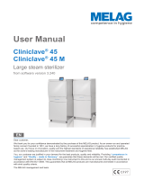
1 Distilled water tank
2 LED screen
3 Control panel
4 Main Power switch
5 Drain valve of distilled water tank
6 Drain valve of used water tank
7 Door handle
8 USB port (optional)
9 Printer port
10 Printer power
11 Safety valve
12 Condenser ventilation
13 Circuit breaker
14 Power supply cord
15 Rating plate
Security Notice
For safe operation, please pay close attention to the alert symbols
below which cab be found throughout this manual. Please
carefully read and understand the contents of this manual prior to
operating this instrument.
This symbol represents an electrical caution - ground protection
HOT SURFACE.
This symbol represents a warning of a potential hot surface.
Important safety information.
This symbol represents a warning for extra caution
Instructions manual
4
3
2
1
6
57
8
9
10
15
14
13
12
11

2 Technical Specifications
Chamber
Rated Voltage
Main Fuses
Sterilization Temperature
Capacity of the distilled
water tank
Operation temperature
Exterior Dimensions
Noise Level
Relative Humidity
Atmospheric pressure
Item
Parameter
Φ170mmX320mm
110V-130V or 220V-240V, AC, 50-60Hz
F25A/250V for 110V or F16A/250V for 220V
250°F/274°F
Approx 2.5L (water at level MAX)
Approx 0.5L (water at level MIN)
41 - 104°F
445mm(width)X 410mm(height)X 605mm(depth)
11.0psi-15.4psi
max. 80%, non condensing
<70dB
Nominal power
1400VA
Weight
66 lb
Instructions manual
2
No.
2
3
4
5
6
7
1
8
3 Packing Content
Quantity
Item
Instrument tray
Instrument tray rack
Instrument tray handle
Door adjustment tool
Draining hose
Instructions manual
2
1
1
1
2
1
1
Steam sterilizer
1
Door seal

3
Instructions manual
4 Installation
Ensure that the sterilizer is installed with 2.5in. (10cm) ventilation space on all sides of the
sterilizer, and 5 in. (20cm) on top side. The clearance required to open the door is 15.5in.
(40cm).
The sterilizer should be placed on a level worktable.
Do not cover or block the door, ventilation or radiation openings on the sterilizer.
Do not install the sterilizer near a sink or in a location where it is likely tobe splashed.
Do not install the sterilizer nearby a heat source.
5.1 Setup
5.1.1 Open the door and remove all of the inner contents for unpacking.
5.1.2 Connect the power cord to an outlet of the appropriate voltage
5.1.3 Power on
The switch is located underneath the control panel
on the front side of the machine .
After switching on, the machine turns on the LCD
and shows the door position, water level,
working program, date, time and etc.
5 Operation
Door locked
information output to USB port
Printer is connected
T emperat ure
Pressure
Program
Alarm code
process curve
Setting
Time
Date
F
F
F
Distilled water tank is requires water.
Distilled water tank is full
Used water tank is full.
565565
370370
345345
760760

Instructions manual
4
Notice: Before using the sterilizer or at any time the low water icon blinks, it is
necessary to fill the distilled water tank with distilled water.
5.1.4 Filling the distilled water
Remove the cover, and fill the tank with distilled water.
When you hear a beep signal, it means the water level exceeds the
max. level. The will be displayed. Please stop filling immediately.
5.2 Preparation of sterilization materials
For the most effective sterilization and to preserve the sample, please
follow below:
* Arrange the samples of different material on different trays or with at least
2in. of space between them.
* Always insert a sterilization paper or cloth between the tray and sample,
to avoid direct contact between the different materials.
The water level should not
exceeded this port.
5.3 Selecting the sterilization program
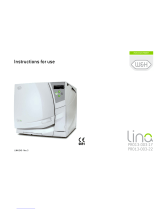
5.3.1 LCD
The panel displays the cycle
temperature, pressure, error code,
sterilization state and program.
5.3.2 Temperature button
Press this button to toggle
between 121°C and 134°C
5.3.3 Program button
Press this button to toggle between
available sterilization cycles (see below)
5.3.4 START/STOP button
Press this button to start the sterilization cycle. To stop a cycle, press
and hold this button for 3 seconds.

5
Notice: Button will be “locked” for the initial 10 seconds after power up for system
initialization.
Instructions manual
UNWRAPPED
(SOLID)
WRAPPED
EXTENSIVE
(PRION)
DRYING
274
F
F
LIQUID
Caution:You must turn the door handle to the maximum position, otherwise
the machine will alarm and prevent completing the cycle.
5.4 Running the sterilization program.
After selecting program, the materials to be
sterilized can now be placed on the tray and the
tray placed inside the chamber using the tray
5.4.1 After the instruments are loaded, you may
close and lock the door by turning the door
handle clockwise until it stops.
5.4.2 Start the sterilization program.
Press START button, the machine will begin the cycle automatically.
It will take 30-75 minutes. (See Appendix 2)
total time or
count down until
completion
F
Caution: When you press the START button but the door has not been fully closed. You will
see the blinking on the screen. A cycle can not be started until you close the door to the
max. position and press the "Start" button again.

Instructions manual
6
5.4.3 Sterilization cycle completion
F
Always use the tray handle to load or unload the tray into the autoclave.
Failure to do so can result in burning.
After a cycle is completed, the printer will be activated and print out a report of the cycle
settings (if the optional printer has been connected).
After the pressure returns to 0, the door is unlocked and the materials can be
If you need to interrupt a cycle and remove materials urgently. you may hold the START
button for 3 seconds after completing sterilization time to skip the dry cycle.
This will result in the program skipping directly to the last step and eliminate the drying
stage. After one minute the cycle
6 Advanced Setting
6.1 Enter the setting
F
6.1.1 Power on the machine while Holding the START button
and hold for 5seconds. This will enter into the advanced
settings mode.
6.1.2 Select the state (State 1 thru. 3) by pressing the Program
button. Press the START button to enter the setting.
6.2 S1 state
If you select the S1. You may change the unit of
temperature and pressure, and adjust time and date.
6.2.1 The first option is to select the unit of temperature. Press
temperature button to select ℃ or .
The unit you selected will be lighted. Press the program
button to the next item.
6.2.2 You may select the unit of pressure in the same manner.
6.2.3 Then press program button to the next item to adjust the time and date. After the
last word of the date or time is set , then the data is permitted to be saved. If you want to
finish the setting you shall press START. It will return to the screen of selecting states.
6.3 S2 state
6.3.1 You may check the count of sterilization cycle. It can not be changed by operator.

7
Instructions manual
cycle No
machine No
Altitude set
Language set
The Machine No. And cycle No can not be set by the operator.
6.5 Printer (Optional)
6.5.1 Connect the printer cable.
6.5.2 Connect the printer power.
holding time
drying time
Notice: the default sterilization parameters have been chosen to provide optimal
sterilization results. We do not suggest adjusting these parameters unless it is necessary.
6.4 S3 state
6.4.1 Adjust the length of sterilization and drying time.
Press program button to select the program.( )
Press temperature button to select the temperature of program.
Then press START to adjust the drying time and holding time.
6.4.2 First to adjust the holding time.
Press temperature button to adjust the data.
Press the program button to select
the items.
6.4.3 Press START to save .
6.4.4 Drying time is 0-19.
Holding time of 250 is 1-59.
Holding time of 274 is 1-19.
F
F
274
F
6.3.2 Set the parameter for high altitude.
If you have trouble completing a cycle in a location
of high altitude (above 2.0 km or atmospheric pressure is
below 80kPa)
you may need to adjust this parameter.
6.3.3 Language set:
00 English 01 German 02 Spanish 03 Polish
04 French 05 Magyar 06 Romanian 07 Dutch
08 Lithuanian 09 Latvian
A USB drive can be used as a method of storing a report of the cycle. To do so, insert the
USB drive to the slot on the right side of the instrument.
The information will automatically output directly to the USB after the cycle has
completed.The name of the file is determined by the serial number of the machine
and the cycle number.
For example:
The serial number is E00001. The cycle number is 00012.
The file name in the USB stick is 01001200.txt.
The first two numbers represent machine number.
The middle four numbers represent cycle number.
The last two numbers represent error code.
00:no error;01: error E01
6.6 USB Flash memory (Optional)

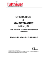
When vieing printed data records, refer to the diagram below:
1
2
t1
t 3
t5
t8
t2
t4
t7
ts
P
t
t6
Instructions manual
8
Press PROGRAM repeatidly until you enter the prior
program storage screen. This will show the cycle No.
Press the TEMP button to toggle between different
cycles.
To print or send details to the USB drive, press the
START button. The most recent 20 records are stored.
6.7 Retrieve information from a prior cycle
=========================
Program: WRAPPED
Temperature: 274 F
Pressure:30.5 psi
Dry Time: 03Min
Ster Time: 4.0Min
-------------------------------------
time temp. pressure
Start 15:24:20 107.6 F
T1: 15:32:11 158.0 F 07.71psi
T2: 15:36:08 167.5 F 01.42psi
T3: 15:39:21 194.5 F 07.30psi
T4: 15:44:32 094.3 F 01.39psi
T5: 15:47:12 201.7 F 14.91psi
T6: 16:00:11 230.3 F 01.35psi
TS: 274.6 F 32.14psi
Max.Temperature:275.2 F
Min.Temperature:274.1 F
Max.Pressure:33.42psi
Min.Pressure:30.88psi
T7: 16:04:02 275.0 F 32.42psi
T8: 16:06:32 274.6 F 31.05psi
End 16:14:12 172.8 F
--------------------------------------
Cycle No: 0005
Ster Value: Success
Date: 2011-01-18
SN:E00001
Operator:
=======================
=========================
Program: WRAPPED
Temperature: 274 F
Pressure:30.5 psi
Dry Time: 03Min
Ster Time: 4.0Min
-------------------------------------
time temp. pressure
Start 17:34:20 179.6 F
T1: 17:42:11 194.0 F 07.57psi
T2: 17:46:08 185.5 F 01.41psi
T3: 17:49:21 226.9 F 07.75psi
T4: 17:54:32 212.5 F 01.39psi
T5: 00:00:00 000.0 F 000.0psi
T6: 00:00:00 000.0 F 000.0psi
TS: 000.0 F 000.0psi
MAX.Temperature:000.0 F
MIN.Temperature:000.0 F
MAX.Pressure:000.0psi
MIN.Pressure:000.0psi
T7: 00:00:00 000.0 F 000.0psi
T8: 00:00:00 000.0 F 000.0psi
End 17:54:42 212.4 F 01.46psi
--------------------------------------
Cycle No: 0007
Ster Value: Failure E01
Date: 2011-01-18
SN:E00001
Operator:
=======================

9
Instructions manual
Clean the external surface
Maintenance Operation
Clean the door seal
Clean the distilled water tank
Clean the sterilization chamber
Replace the door seal
7.1 Clean the distilled water tank every
week with isopropyl alcohol or a
medical disinfectant.
7.2 Clean the chamber weekly.
7.2.1 Remove all trays and the tray rack
from the chamber.
7.2.2 Clean the chamber with a
smooth cloth saturated with
distilled water.
7.2.3 Apply the same procedure for
the trays and rack.
Frequency
7. Maintenance
7 Maintenance
Weekly
Every year
Daily
Every month
(depending on the use)
Clean the filter inside the chamber and tank
7.3 Clean the door seal
Clean the door seal weekly, with a smooth cloth saturated with the
distilled water.

1 0
Instructions manual
Fig 1
Fig 2
Caution: Never adjust the chamber door while the door is closed.
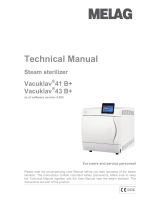
7.4 Door adjustment
On normal circumstance the chamber door does not require adjustments.
However, if the seal fails (resulting in steam leaking from the front of
the chamber), you may use the included tool to tighten the door seal.
7.4.1 Open the door
7.4.2 Insert the spanner tool in the gap beneath the plastic cover; use the spanner
to grip the adjusting nut (Fig 1). Turn the nut counter clockwise as
the figure below (Fig 2). This will tighten the sealing plate.
7.4.3 Turn the nut until the sealing plate is tight. If the door knob is too tight,
you may also turn the nut clockwise to loosen it.
7.5 The drain valve
1.Press the included hose on to the
drain valve firmly.
2.Set the drain valve to the open
position by turning it counter
clockwise.
3.Pull the drain valve outward, the
tank will begin to drain.
4.After finish draining the tank, push
the drain valve inward and turn
clockwise into the closed position.

11
Instructions manual
1). Press in the top and bottom
of the seal ring.
2). Press in the left and right sides
of the seal ring.
3). Press the remaining sections
of the seal ring.
4). Press all areas of the seal
surface for a smooth finish.
Caution: Please ensure the chamber and the door have cooled prior to
replacing the seal ring.
7.6 Replacement of the door seal
7.6.1 Open the chamber door.
7.6.2 Remove the door seal ring carefully by hand.
7.6.3 Clean the door seal ring carefully with a smooth cloth saturated with distilled water.
7.6.4 Moisten the new seal with medical disinfectant or isopropyl alcohol.
7.6.5 Insert the new seal and press in sequence as follows:
8 Transportation and Storage
8.1 Switch off the sterilizer before transportation or storage. Pull out the
plug to let the machine cool down.
8.2 Drain the distilled water tank and the used water tank.
8.3 Conditions for transportation and storage:
Temperature: -20 ℃ ~ +55 ℃
Relative humidity: ≤85%
Atmospheric pressure: 50kPa~106kPa

1 2
Instructions manual
9 Error codes
Code
E1
E2
E3
E4
E5
E6
Description Proposed solution
Steam generator tempe rature
sensor error
Temperature senso r of chamber
wall erro r
Inner tempera ture sensor erro r
Fail to rise temperature
Fail to release the pressure
Door has opened during the
cycle
Failure to hold temperature
Program manually interru pted
Power off & run a new cycl e
Cont act you r Supp lier if error per sists
Power off & run a new cy cle
Contact your Supplier if erro r persist s
Care full y en su re that the ch amber wall
is heated. If not contact your su pplier
Check to ensur e that the used water
val ve is ful ly cl osed.
Power off & run a new cycle
Contact your Supplier if erro r persist s
Make sure you have turn ed the door handle
to th e max. Posit ion or check the door sw itch
Shut off the power and restart the
power
Ensure the distilled water tank isn't empty
Check the inner temperature sensor
Check the door for leaking
E20
E9
Fail ure to pre heat th e chamber
E12
E11
Failure to preheat the steam
generator
Check the steam generator heater
Check the steam generator protector
Check the chamber heater
Check chamber protector

(1)Main fuses
Protect the instrument against possible failures of the
heating resistor .
Action: Interruption of the electric power supply.
(2)Thermal cutouts on the main transformer windings
Protection against possible short circuit and main transformer primary
winding overheating .
Action: Temporary interruption of the winding.
(3)Safety valve
Protection against possible sterilization chamber over-pressure .
Action: release of the steam and restoration of the safely pressure.
(4)Safety micro-switch for the door status
Comparison for the correct closing position of the door .
Action: signal of wrong position of the door.
(5)Door safety lock
Protection against accidental opening of the door.
Action: Impediment of the accidental opening of the door during the program.
(6)Self-leveling hydraulic system
Hydraulic system for the natural pressure leveling in case of manual cycle
interruption, Alarm or black-out .
Action: automatic restoration of the atmospheric pressure inside chamber.
10 Safety devices
1 3
Instructions manual

APPENDIX 1
1 4
Instructions manual
DESCRIPTION
FEED WATER
CONDENSATE
Evaporate residue
Silicium oxide sio
2
Iron
Cadmium
Lead
Rest of heavy metals, excluding
iron, cadmium, lead
Chloride
≤10 mg/l
≤1 mg/l
≤0.2 mg/l
≤0.005 mg/l
≤0.05 mg/l
≤0.1 mg/l
≤2 mg/l
≤1.0 mg/kg
≤0.1 mg/kg
≤0.1 mg/kg
≤0.05 mg/kg
≤0.1 mg/kg
≤0.1 mg/kg
≤0.1 mg/l
Phosphates
Conductivity (at 20℃)
pH value
Appearance
Hardness
≤0.02 mmol/l
Colorless, clean,
without sediments
5-7.5
≤15μs/cm
≤0.5 mg/l
≤0.1 mg/l
≤3μs/cm
5-7
≤0.02 mmol/l
Colorless, clean,
without sediments
Water Properties/Characteristics

DIAGRAMS OF THE STERILIZATION PROGRAMS
APPENDIX 2
The max. temperature of the 274 F sterilization cycle is 279 F
The max. temperature of the 250 F sterilization cycle is 256 F
PROGRAM
UNWRAPPED
(SOLID)
LIQUID
EXTENSIVE
(PRION)
DRYING
Te
mper
a
ture
)
( F
274 30.5 4 14-25
274 30.5 18 30-50
274 30.5 10 25-50
250 16.0 30 30- 55
250 16.0 20 25-40
。
Pre
ss r
eu
(
ps
i)
o
ldin
g t
i
mH e
(
min)
T
o
ta
tim
el
(
mi
n
)
1-20
Unwrapped porous material
Single-wrapped porous
material
Single-wrapped hollow
material
Dual- wrapped porous
material
Dual- wrapped solid and
hollow material
Unwrapped solid
material
TYPE
Liquid
1. 50 0.50
1. 00 0.30
0. 50 0.15
0. 35 0.10
0. 25 0.10
.
L
oadM
ax
2. 00 0.60
0. 60 0.20
( gk
)
.Lo
a
d
Ma
x
) ap
er
t
r y
(kg
274 30.5 4 25-45
250 16.0 20 25- 50
WRAPPED
Unwrapped porous material
Single-wrapped solid or
hollow material
1. 50 0. 60
2. 00 0. 60
1 5
Instructions manual

0.0
UNWRAPPED
Pressure(psi)
Pressure(psi)
Time(min)
Time(min)
WRAPPED
EXTENSIVE
1 6
Instructions manual
0.0
0.0
Pressure(psi)
0.0
Pressure(psi)
Time(min)
Time(min)
DRYING
LIQUID

1 7
Instructions manual
WIRING DIAGRAM
TANK MAX. LEVEL
PRESSURE SENSOR
V4
V1
PRINTER
POWER
KEYBOARD
DATA LINE
DOOR CLOSE
Tp1
Tp2
Tp3
~~
VACUUM
PUMP
~
9V(2.5A)
~
9V(0.2A)
~21.5V
~ 0V
FAN
WATER
PUMP
STEAM
HEATER
THERMAL
PROTECTOR
CHAMBER
HEATER
THERMAL
PROTECTOR
PUBLIC
TANK MIN. LEVEL
PRINTER
OUTPUT
USB DATA
OUTPUT
USED WATER TANK
TP1: Steam generator temperature sensor
TP2: Inner temperature sensor
TP3: Temperature sensor of chamber wall
V1: Air release valve
V4: Water release valve
-
+
APPENDIX 3
/