BRAVILOR BONAMAT Bolero XL 433 S Owner's manual
- Type
- Owner's manual
This manual is also suitable for
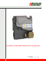
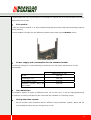
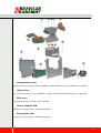
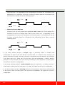
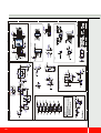
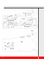
The BRAVILOR BONAMAT Bolero XL 433 S is an advanced coffee machine designed to provide a range of hot beverages with ease and efficiency. It features a user-friendly control panel with clear buttons and a large display, making it simple to select and customize your desired drinks. With its large capacity, it can produce up to 433 cups per hour, making it suitable for busy environments such as offices, restaurants, and hotels. This machine offers various programmable options, allowing you to tailor it to your specific needs and preferences.
The BRAVILOR BONAMAT Bolero XL 433 S is an advanced coffee machine designed to provide a range of hot beverages with ease and efficiency. It features a user-friendly control panel with clear buttons and a large display, making it simple to select and customize your desired drinks. With its large capacity, it can produce up to 433 cups per hour, making it suitable for busy environments such as offices, restaurants, and hotels. This machine offers various programmable options, allowing you to tailor it to your specific needs and preferences.


-
 1
1
-
 2
2
-
 3
3
-
 4
4
-
 5
5
-
 6
6
-
 7
7
-
 8
8
-
 9
9
-
 10
10
-
 11
11
-
 12
12
-
 13
13
-
 14
14
-
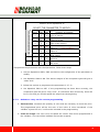 15
15
-
 16
16
-
 17
17
-
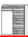 18
18
-
 19
19
-
 20
20
-
 21
21
-
 22
22
-
 23
23
-
 24
24
-
 25
25
-
 26
26
-
 27
27
-
 28
28


BRAVILOR BONAMAT Bolero XL 433 S Owner's manual
- Type
- Owner's manual
- This manual is also suitable for
The BRAVILOR BONAMAT Bolero XL 433 S is an advanced coffee machine designed to provide a range of hot beverages with ease and efficiency. It features a user-friendly control panel with clear buttons and a large display, making it simple to select and customize your desired drinks. With its large capacity, it can produce up to 433 cups per hour, making it suitable for busy environments such as offices, restaurants, and hotels. This machine offers various programmable options, allowing you to tailor it to your specific needs and preferences.
Ask a question and I''ll find the answer in the document
Finding information in a document is now easier with AI

Other documents
-
Dakota Alert AD-SSW User manual
-
 C. Crane A-66 User manual
-
innovative technology BV20 User manual
-
-
-
 Advanced Technology International USA M200 User manual
-
Sentinel Unitec Owner's manual
-
-
 EVOCA Manual User manual
-


