Baumer OM70-P0250.HH0130.EK Operating instructions
- Category
- Measuring & layout tools
- Type
- Operating instructions

Operating Instructions
OM70 - High performance distance sensors
with Ethernet interface

en_BA_OM70_Eth_point_line.docx 2/81 Baumer Electric AG
08.04.2020 12:05/adr Frauenfeld, Switzerland
Contents
1 General information ...................................................................................................................... 4
1.1 Concerning the contents of this document ..................................................................................... 4
1.2 Safety instructions .......................................................................................................................... 4
1.3 Liability limitation ............................................................................................................................. 4
2 Product information ..................................................................................................................... 5
2.1 Functionality .................................................................................................................................... 5
2.2 Dimensions ..................................................................................................................................... 5
2.3 Sensor inscriptions ......................................................................................................................... 6
2.4 Laser radiation ................................................................................................................................ 6
2.5 Status LEDs on the sensor ............................................................................................................. 7
2.6 Definition of the measuring range ................................................................................................... 7
2.7 Transmitter and receiver axis.......................................................................................................... 8
3 Mounting and connection ............................................................................................................ 9
3.1 Mounting ......................................................................................................................................... 9
3.2 Mounting accessories ..................................................................................................................... 9
3.2.1 Alignment ...................................................................................................................................... 10
3.3 Electrical connection ..................................................................................................................... 13
3.3.1 Pin assignment and connection diagram ...................................................................................... 13
3.3.2 Connection cables ........................................................................................................................ 14
4 Configuration via web interface ................................................................................................ 15
4.1 Starting up the Ethernet interface on the PC ................................................................................ 16
4.1.1 Allocation of an IP address ........................................................................................................... 16
4.1.2 Identifying an unknown sensor IP address ................................................................................... 16
4.2 The web interface ......................................................................................................................... 16
4.2.1 Connecting the web interface ....................................................................................................... 16
4.2.2 Overview web interface ................................................................................................................ 17
4.3 Monitoring ..................................................................................................................................... 18
4.3.1 Measurement Mode ...................................................................................................................... 18
4.3.2 Result over time ............................................................................................................................ 18
4.3.3 Measuring conditions .................................................................................................................... 19
4.4 Parameterization ........................................................................................................................... 22
4.4.1 Line Signal & Raw Line Signal ...................................................................................................... 22
4.4.2 Active Parameters ........................................................................................................................ 23
4.5 Device Configuration .................................................................................................................... 35
4.5.1 Sensor Information ....................................................................................................................... 35
4.5.2 Network ......................................................................................................................................... 35
4.5.3 Time Synchronization ................................................................................................................... 35
4.5.4 Process interface .......................................................................................................................... 36
4.5.5 Parameter Setup Overview ........................................................................................................... 36
4.5.6 Web interface & firmware ............................................................................................................. 36
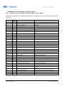
5 Communication via Profinet IO interface ................................................................................. 37
5.1 Profinet device integration ............................................................................................................ 37
5.2 Module overview ........................................................................................................................... 37
5.1 Module Overview .......................................................................................................................... 39
5.1.1 Category 00_Measurements ........................................................................................................ 39
5.1.2 Category 10_Device Configuration ............................................................................................... 41
5.2 Factory Reset................................................................................................................................ 43

en_BA_OM70_Eth_point_line.docx 3/81 Baumer Electric AG
08.04.2020 12:05/adr Frauenfeld, Switzerland
6 Communication via Modbus TCP interface ............................................................................. 44
6.2 Protocol parameters ..................................................................................................................... 44
6.3 Mapping the sensor functionality to the Modbus data model ....................................................... 44
6.4 Modbus TCP commands: Holding register ................................................................................... 45
6.4.1 Overview of index commands for holding register function 03/6/16 ............................................. 45
6.4.2 Modbus TCP commands: Input register ....................................................................................... 51
6.4.1 Modbus TCP commands: Discrete Input register ......................................................................... 59
7 OPC UA ........................................................................................................................................ 60
8 UDP Streaming ............................................................................................................................ 61
9 Error Correction .......................................................................................................................... 62
10 Maintance .................................................................................................................................... 62
11 Disposal ....................................................................................................................................... 62
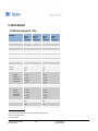
12 Sensor data sheet ....................................................................................................................... 63
12.1 Measuring range types 30…70 mm ............................................................................................. 63
12.2 Measuring range types 40…140 mm ........................................................................................... 66
12.3 Measuring range types 50…250 mm ........................................................................................... 69
12.4 Measuring range types 100…600 mm ......................................................................................... 72
12.5 Measuring range types 100…1000 mm ....................................................................................... 75
12.6 Measuring range types 150…1500 mm ....................................................................................... 78

en_BA_OM70_Eth_point_line.docx 4/81 Baumer Electric AG
08.04.2020 12:05/adr Frauenfeld, Switzerland
1 General information
1.1 Concerning the contents of this document
This manual contains information for the mounting and start-up of Baumer OM70 high performance distance
sensors. It is a supplement to the mounting instructions supplied with each sensor.
Carefully read the operating instructions prior to the use of the product and observe the safety
instructions! In addition, the operating instructions must be kept and made available for future
reference.
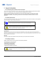
1.2 Safety instructions
The following symbols emphasize safety and warning instructions in this manual. The safe use of this product
requires compliance with the safety instructions.
Intended use
This product is a precision device and serves the identification of items and objects and the preparation or
provision of measured values for the subsequent system. Unless specifically labeled, this product may not be
used in explosive environments.
Start-up
Assembly, mounting and calibration of this product may only be performed by a specialist.
1.3 Liability limitation
Liability of Baumer Electric AG is excluded for the following situations:
• Non-observance of the instructions
• Non-intended use of the product
• Deployment of untrained staff
• Use of unapproved spare parts
• Unapproved modification of products
NOTE
Provides helpful operation instructions or other general recommendations.
CAUTION!
Indicates a potentially hazardous situation. Avoid these situations in order to
prevent any personal injury or damage to the device!
CAUTION!
Deviations from the processes and settings stated here can result in hazardous
situations!

en_BA_OM70_Eth_point_line.docx 5/81 Baumer Electric AG
08.04.2020 12:05/adr Frauenfeld, Switzerland
2 Product information
2.1 Functionality
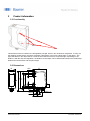
This distance sensor is based on the triangulation principle, which in turn is based on angulation. To carry out
the distance measurement, the sensor transmits a light beam, in this case a laser beam, to the object . The
light reflected from the object strikes a receiver line inside the sensor at a special angle, depending on the
distance. With the help of triangulation, the distance to the object can be determined based on the relationship
between the transmission and reception angle.
2.2 Dimensions
26
74
85
64
5
M12 x 1
M12 x 1
14
50
7 9
9
4,3
19
4,5 2
21
LED
55
Near
Far

en_BA_OM70_Eth_point_line.docx 6/81 Baumer Electric AG
08.04.2020 12:05/adr Frauenfeld, Switzerland
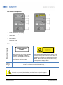
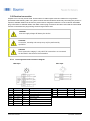
2.3 Sensor inscriptions
1. Laser class notice/ warning sign
2. FDA certification sign
3. Article name
4. Serial number
5. MAC address
6. Material number
7. Production code
2.4 Laser radiation
Notice and warning sign
Class 1: No risk for the eye
Class 1 lasers are safe under reasonably
foreseeable operational conditions of
normal use, including direct long-term
viewing of the beam, even when exposure
occurs using a magnifying optic.
Class 2: Do not stare into the beam
Accidental short-term exposure (up to 0.25 s) does
not damage the eye, because the corneal reflex can
automatically protect the eye sufficiently from longer
radiation. Class 2 lasers may be used without any
further protection if intentional staring into the beam
is not required for the application.
FDA
certifica
tion
CLASS 1 LASER
PRODUCT
IEC 60825-1/2014
Complies with 21 CFR 1040.10 and 1040.11
except for deviations pursuant to laser
notice No. 50, dated June 24, 2007
LASER RADI ATION
DO NOT S TARE IN TO BEAM
Wavelength: 640...670nm
IEC 60825-1, Ed. 3, 2014
CLASS 2 LASER PRODUCT
Complies with 21 CFR 1040.10 and 1040. 11 except for deviations
pursuant to laser notice No. 50, dated June 24, 2007
CAUTION!
When using a sensor with broken front panel, defective display, loose or
separated lens, it must be immediately separated from the power supply to
prevent the emission of laser radiation.
Complies with 21 CFR 1040.10 and 1040.11
except for conformance with IEC 60825-1 Ed. 3.,
as described in Laser Notice No. 56, dated May 8, 2019

en_BA_OM70_Eth_point_line.docx 7/81 Baumer Electric AG
08.04.2020 12:05/adr Frauenfeld, Switzerland
2.5 Status LEDs on the sensor
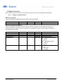
2.6 Definition of the measuring range
The sensor measures distances within the measuring range. The important definitions are described in the
following figure. The reference level R2 applies as a reference for 0 in the delivery condition.
Blind region
The area from reference level R2 to the start of the measuring range Sdc is called blind region, the sensor
cannot detect any objects there.
If there are any objects in this region, this can lead to incorrect measured values.
LED
Illuminated
Flashes
Yellow
Switching Output
Switching output (out 1) is active.
-
Red
Alarm Output
Alarm output (out 2) is active. No object
within the measuring range or signal
quality is inadequate.
Signal Reserve
Signal Quality close to the signal reserve.
Green
Supply Voltage
Sensor ready for operation, Ethernet
connection not available.
Short Circuit
Check connection to the Switching or Alarm Output.
Blue
Ethernet Link
Sensor ready for operation, Ethernet
connection available.
Data Transfer
Data packages are received or transmitted via
Ethernet.
Measuring range
Mr
End of the
measuring range
Sde
Start of the
measuring range
Sdc
R2
Blind region
Switching Output
Alarm Output
Power / Link
Switching Output
Alarm Output
Power / Link

en_BA_OM70_Eth_point_line.docx 8/81 Baumer Electric AG
08.04.2020 12:05/adr Frauenfeld, Switzerland
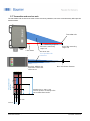
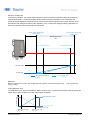
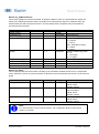
2.7 Transmitter and receiver axis
The transmitter and receiver axes must not be covered by obstacles, since this could adversely affect precise
measurements.
L1
Laser beam
Measuring range Mr
Receiver axis:
Area prohibited for
obstacles
End of the measuring
range Sde
Start of the measuring
range Sdc
19 mm
L2
13 mm
Area prohibited for
obstacles
Receiver: width14 mm
around the central axis
of the sensor
Max. laser beam diameter
Transmitter axis
Dimensions L1 and L2 see
receiver position according to the
sensor datasheet section.
14 mm

en_BA_OM70_Eth_point_line.docx 9/81 Baumer Electric AG
08.04.2020 12:05/adr Frauenfeld, Switzerland
3 Mounting and connection
3.1 Mounting
Only use the fasteners and fastener accessories intended for this product for the mounting.
3.2 Mounting accessories
The sensor is equipped with four fastening slits through which it can be flexibly aligned and mounted. For the
fastening 2 screws M4x35 and suitable washers are recommended, the maximum torque is 1.2 Nm.
Accessories for easy assembly are linked to the respective product page on the Baumer homepage. Enter the
article number in the search field on www.baumer.com and open the product page.
CAUTION!
Connection, mounting and start-up may only be performed by
specialists. Protect optical surfaces from humidity and soiling to prevent
measurement errors.

en_BA_OM70_Eth_point_line.docx 10/81 Baumer Electric AG
08.04.2020 12:05/adr Frauenfeld, Switzerland
3.2.1 Alignment
To achieve as reliable and exact measured values as possible, the following hints and tips for mounting should
be followed.
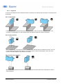
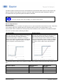
3.2.1.1 Steps/edges
If measurements are carried out directly beside steps/edges, make sure that the reception beam is not
covered by the step/edge. The same applies when the depth of holes and cracks is measured.
3.2.1.2 Shiny surfaces
With shiny surfaces, it is important to ensure that the direct reflection does not strike the receiver. This can
be prevented by tilting the sensor slightly. To check this, place a sheet of white paper on the disc of the
receiver; the direct reflection can then be seen clearly.
3.2.1.3 Round shiny surfaces
With round, shiny surfaces, the sensor should be aligned in the same axis as the round object in order to
avoid reflections.

en_BA_OM70_Eth_point_line.docx 11/81 Baumer Electric AG
08.04.2020 12:05/adr Frauenfeld, Switzerland
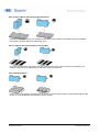
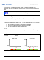
3.2.1.4 Shiny objects with evenly aligned structure
Particularly with shiny objects, for example turned parts, ground surfaces, extruded surfaces and the like,
the mounting position affects the measuring result.
3.2.1.5 Objects with evenly aligned colored edges
In the correct orientation, the influence on the measuring accuracy is low. In the wrong orientation, the
deviations depend on the differences in reflectivity of the various colors.
3.2.1.6 Moving objects
If the contour of an object is measured, it is important to ensure that the object moves at right angles to the
sensor, to avoid shadowing and reflections on the receiver.

en_BA_OM70_Eth_point_line.docx 12/81 Baumer Electric AG
08.04.2020 12:05/adr Frauenfeld, Switzerland
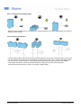
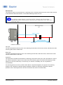
3.2.1.7 Protection from ambient light
When mounting optical sensors, it is important to ensure that there is no strong ambient light in the area of
detection of the receiver.
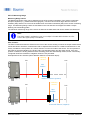
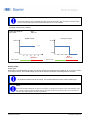
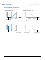
3.2.1.8 Reciprocal influence
If several optical sensors are used, they may mutually influence one another. During mounting, ensure that
only the sensor's own laser spot is in the detection range of the receiver. Up to a measuring range of 600
mm, the sensors can be lined up in a row without them influencing each other (picture in the middle).
If the mutual interference cannot be avoided through mounting, the sensors can be operated
asynchronously using the Sync-in input, see section "Trigger Mode".

en_BA_OM70_Eth_point_line.docx 13/81 Baumer Electric AG
08.04.2020 12:05/adr Frauenfeld, Switzerland
3.3 Electrical connection
Outputs not in use may not be wired. Unused wires of cable outputs must be insulated. Do not go below
permissible cable bending radii. The system must be switched off before electrically connecting the product. If
required, shielded cables must be used to prevent electro-magnetic interference. If the customer assembles
plug connections to shielded cables, then EMC-version plug connections should be used and the cable shield
must be connected to the plug housing across a large surface area.
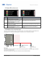
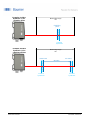
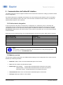
3.3.1 Pin assignment and connection diagram
M12 8-pin M12 4-pin
Color
Function
Description
Pin 1
WH = white
Tx+
TX+ (BI_DA+)
Pin 2
BU = blue
Rx+
RX+ (BI_DB+)
Pin 3
YE = yellow
Tx-
TX- (BI_DA-)
Pin 4
OG = orange
Rx-
RX- (BI_DB-)
Color
Function
Description
Pin 1
WH = white
Teach
Teach Input (Zero Position)
Pin 2
BN = brown
+ Vs
Operating voltage (+15 … +28 VDC)
Pin 3
GN = green
Analog
Analog Output
Pin 4
YE = yellow
out
Switching Output
Pin 5
GY = gray
alarm
Alarm Output
Pin 6
PK = pink
n.c.
Not connected
Pin 7
BU = blue
0V
GND
Pin 8
RD = red
Sync-in
Synchronization Input
CAUTION!
The IP protection category is only valid if all connections are connected
as described in the technical documentation.
CAUTION!
Connection, mounting and start-up may only be performed by
specialists.
CAUTION!
Incorrect supply voltage will destroy the device!

en_BA_OM70_Eth_point_line.docx 14/81 Baumer Electric AG
08.04.2020 12:05/adr Frauenfeld, Switzerland
3.3.2 Connection cables
Accessories for a professional connection are linked to the respective product page on the Baumer
homepage. Enter the article number in the search field on www.baumer.com and open the product page.
NOTE
We recommend that you connect unused cables to GND (0V).

en_BA_OM70_Eth_point_line.docx 15/81 Baumer Electric AG
08.04.2020 12:05/adr Frauenfeld, Switzerland
4 Configuration via web interface
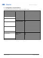
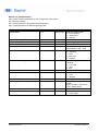
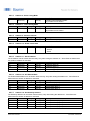
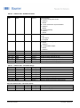
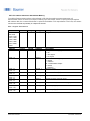
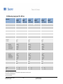
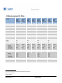
The following table presents an overview of the settings in the delivery condition.
Parameterization/configuration option
OM70-x.EK
Language
English
Trigger Mode
Free Running
Measuring Range Limits
Sdc…Sde
Zero Position
0 mm (sensor front)
Precision Filter
Very high
Invalid Value Handling
Value after Dropout
Near
Hold Time
0 ms
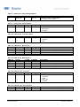
Analog Output
Output Type
4 - 20 mA
Min. Output Point
Sdc
Max. Output Point
Sde
Inverted Characteristics
Off
Switch Points
Switching Mode
Window
Far Point
Sde - 10 mm
Near Point
Sdc + 10 mm
Hysteresis
MR / 1000
Polarity
Active low
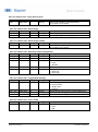
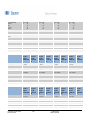
Network
IP address
192.168.0.250
Subnet mask
255.255.255.0
Standard gateway
192.168.0.1
DHCP
Off
MAC address
See label inscriptions
Time synchronization
NTP
On
Time server
192.168.0.1
Process interface
Modbus TCP/ IP
On
OPC UA
On
Profinet
On
UDP streaming
Off
IP address
192.168.0.2
Port
1234
Password protection
Off

en_BA_OM70_Eth_point_line.docx 16/81 Baumer Electric AG
08.04.2020 12:05/adr Frauenfeld, Switzerland
4.1 Starting up the Ethernet interface on the PC
4.1.1 Allocation of an IP address
To use the device in your network you must allocate a unique IP address to the device.
1. If a DHCP server is integrated into the network, this server will allocate the IP address. No other
manual adjustments need to be made.
2. If the DHCP functionality is deactivated or no valid IP address can be determined, the static IP
address is used. In the delivery condition the IP address is 192.168.0.250 (subnet mask:
255.255.255.0).
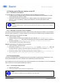
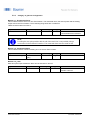
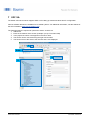
4.1.2 Identifying an unknown sensor IP address
If you don’t know the IP address of the sensor, either because it was assigned via DHCP or the information
about the static IP address is no longer available, you can query the IP address using the following options:
Option 1: Requesting the IP address via mDNS
1. Open a browser window
2. Type the following command in the address line of the browser: OM70-[identifier].local.
Replace [identifier] either with the eight-digit order number or the MAC address indicated on
the sensor. Example: OM70-12345678.local or OM70-11-22-33-44-55-66.local
3. The web interface of the device will be opened.
Option 2: Requesting the IP address via ping-command
1. Open a Windows command prompt
2. Execute the command ping OM70-[identifier].local. Replace [identifier] either with
the eight-digit order number or the MAC address indicated on the sensor. Example: ping OM70-
12345678.local or ping OM70-11-22-33-44-55-66.local
3. Read the IP address (here: 192.168.0.250) from the command output: Ping is executed for
OM70-12345678.local [192.168.0.250] with 32 bytes of data
4.2 The web interface
The device is equipped with an integrated web server that provides a graphical user interface (GUI). This
allows parameterization as well as evaluation of the data directly via the web browser.
Due to differences in browser technology, there may be deviations in the presentation or even incompatibilities
with the device for some browsers and browser versions.
4.2.1 Connecting the web interface
1. Start the web browser
2. Enter the IP address of the sensor in the address line
NOTE
In the delivery condition the set IP address is 192.168.0.250
NOTE
To avoid network errors, you must ensure that each IP address is unique and not already
allocated.

en_BA_OM70_Eth_point_line.docx 17/81 Baumer Electric AG
08.04.2020 12:05/adr Frauenfeld, Switzerland
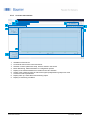
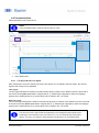
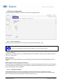
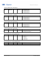
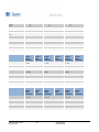
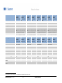
4.2.2 Overview web interface
1. IP address of the sensor
2. Commercial name of the connected sensor
3. Selection of active parameter setup, which is stored in the sensor
4. Mode: Monitoring, Parameterization or Configuration options
5. Display of the measured distance in relation to the Zero Position
6. Output of the measured value as well as the signal quality/switching output over time
7. Overview of active parameters
8. Display warm up, status alarm and switching output.
9. Display of measuring conditions
4
5
6
2
3
1
7
8
9

en_BA_OM70_Eth_point_line.docx 18/81 Baumer Electric AG
08.04.2020 12:05/adr Frauenfeld, Switzerland
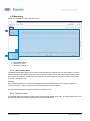
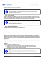
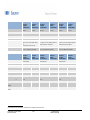
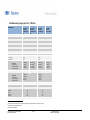
4.3 Monitoring
Output and evaluation of the measured values.
1. Measurement Mode
2. Result over Time
3. Measuring conditions
4.3.1 Measurement Mode
The Measurement Mode shows the currently measured distance depending on the Zero Position. The Zero
Position describes the offset from the front of the sensor housing on which the output measurement results
are based. In the delivery condition the Zero Position is 0, which means it is on the front side of the sensor
(level R2 – see section 2.3).
Example:
Zero Position (displayed) + Distance Value (displayed) = Absolute distance to the measured object, e. g.
100 mm + 50 mm = 150 mm (from front side of the sensor to measured object)
For more information about the Zero Position see section 4.4.2.2.
4.3.2 Result over time
The diagram shows the measured values (blue) within the adjustable "time span". The gray background or the
gray line indicates the switching output window or the switching point.
1
2
3

en_BA_OM70_Eth_point_line.docx 19/81 Baumer Electric AG
08.04.2020 12:05/adr Frauenfeld, Switzerland
4.3.2.1 Signal quality/ Switching output
The color bar underneath the diagram either indicates the signal quality or the switching output. This can be
adjusted by the user via the drop down menu underneath the color bar. If no signal is present, the alarm
output is active.
Signal quality
Green: valid signal
Yellow: low signal
Red: no signal (no valid measured value)
Switching output
Yellow: switching output active
Grey: switching output inactive
4.3.2.2 Store/ Pause
Activating "pause" freezes the diagram. During "pause" the shown measured values can be stored on the PC
in the .csv format by pressing the diskette icon.
4.3.3 Measuring conditions
The measurement conditions can be checked quickly and easily by displaying the exposure reserve, the
response delay, and the measurement rate.
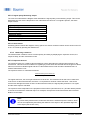
4.3.3.1 Exposure Reserve
The exposure reserve is a relative value that defines a factor describing the reflected light quantity on the
receiver line. This serves as an indicator for signalling by which factor the reflected amount of light can still be
reduced, so that an evaluable signal and thus a valid measurement result can still be obtained.This is a
relative value without a unit.
The exposure reserve is calculated as follows:
𝑀𝑎𝑥𝑖𝑚𝑢𝑚 𝐸𝑥𝑝𝑜𝑠𝑢𝑟𝑒 𝑅𝑒𝑠𝑒𝑟𝑣𝑒
𝐶𝑢𝑟𝑟𝑒𝑛𝑡 𝐸𝑥𝑝𝑜𝑠𝑢𝑟𝑒 𝑅𝑒𝑠𝑒𝑟𝑣𝑒
The higher this factor, the more light reaches the receiver line. The maximum factor that can be reached is
3125 and for a valid measurement, the factor 1 is required as a minimum. Below the factor 1 the sensor
receives too little light and does not issue a valid measured value, the signal quality switches to "no signal"
and the alarm output is activated.
The exposure reserve depends on the properties of the surface (color/structure, etc.) and the relative position
of the sensor towards the measured object. For example, the exposure reserve decreases with increased
distance to the object.
NOTE
To prevent faulty measurement, make sure that there is sufficient exposure reserve, which
can be accomplished by decreasing the distance to the object or the optimized alignment
to the object (see section 3.2.4)

en_BA_OM70_Eth_point_line.docx 20/81 Baumer Electric AG
08.04.2020 12:05/adr Frauenfeld, Switzerland
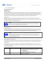
4.3.3.2 Response Delay
Output of the current response delay. The response delay describes the time elapsed between the triggering
of the measurement (internal or external signal on the Sync-in) and the change of the measured value on the
output.
The duration of the response delay depends on the exposure time. The sensor automatically adjusts its
exposure time to the object to always receive an optimal light amount and thus achieve a sufficient exposure
reserve. The exposure time depends on the properties of the surface (color, structure, etc.) and the relative
position of the sensor towards the measured object.
Dark objects reflect less light and thus need longer exposure times than light objects, increasing the response
delay.
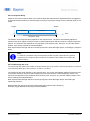
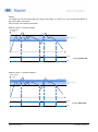
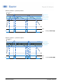
4.3.3.3 Measuring rate in Hz
The measuring rate defines the number of measurements per second. With a measuring frequency of 500 Hz,
a measurement takes place every 0.002 s (1/ 500 Hz = 0.002 s).
The measuring rate value depends on the exposure time. The sensor automatically adjusts its exposure time
to the object to always receive an optimal light amount and thus achieve a sufficient lighting reserve. The
exposure time depends on the properties of the surface (color, structure, etc.) and the relative position of the
sensor towards the measured object.
Dark objects reflect less light and thus need longer exposure times than light objects, decreasing the
measuring frequency.
Measurement and change of the output always take place with the same frequency.
Example (Trigger Mode Free Running and Interval Mode):
Trigger
Response delay
Calculation
Measurement
Time
Output
NOTE
To allow the correlation of the measurement position and the output value for dynamic
applications, the response delay should be considered. Filter settings do not affect the
response delay.
Page is loading ...
Page is loading ...
Page is loading ...
Page is loading ...
Page is loading ...
Page is loading ...
Page is loading ...
Page is loading ...
Page is loading ...
Page is loading ...
Page is loading ...
Page is loading ...
Page is loading ...
Page is loading ...
Page is loading ...
Page is loading ...
Page is loading ...
Page is loading ...
Page is loading ...
Page is loading ...
Page is loading ...
Page is loading ...
Page is loading ...
Page is loading ...
Page is loading ...
Page is loading ...
Page is loading ...
Page is loading ...
Page is loading ...
Page is loading ...
Page is loading ...
Page is loading ...
Page is loading ...
Page is loading ...
Page is loading ...
Page is loading ...
Page is loading ...
Page is loading ...
Page is loading ...
Page is loading ...
Page is loading ...
Page is loading ...
Page is loading ...
Page is loading ...
Page is loading ...
Page is loading ...
Page is loading ...
Page is loading ...
Page is loading ...
Page is loading ...
Page is loading ...
Page is loading ...
Page is loading ...
Page is loading ...
Page is loading ...
Page is loading ...
Page is loading ...
Page is loading ...
Page is loading ...
Page is loading ...
Page is loading ...
-
 1
1
-
 2
2
-
 3
3
-
 4
4
-
 5
5
-
 6
6
-
 7
7
-
 8
8
-
 9
9
-
 10
10
-
 11
11
-
 12
12
-
 13
13
-
 14
14
-
 15
15
-
 16
16
-
 17
17
-
 18
18
-
 19
19
-
 20
20
-
 21
21
-
 22
22
-
 23
23
-
 24
24
-
 25
25
-
 26
26
-
 27
27
-
 28
28
-
 29
29
-
 30
30
-
 31
31
-
 32
32
-
 33
33
-
 34
34
-
 35
35
-
 36
36
-
 37
37
-
 38
38
-
 39
39
-
 40
40
-
 41
41
-
 42
42
-
 43
43
-
 44
44
-
 45
45
-
 46
46
-
 47
47
-
 48
48
-
 49
49
-
 50
50
-
 51
51
-
 52
52
-
 53
53
-
 54
54
-
 55
55
-
 56
56
-
 57
57
-
 58
58
-
 59
59
-
 60
60
-
 61
61
-
 62
62
-
 63
63
-
 64
64
-
 65
65
-
 66
66
-
 67
67
-
 68
68
-
 69
69
-
 70
70
-
 71
71
-
 72
72
-
 73
73
-
 74
74
-
 75
75
-
 76
76
-
 77
77
-
 78
78
-
 79
79
-
 80
80
-
 81
81


Baumer OM70-P0250.HH0130.EK Operating instructions
- Category
- Measuring & layout tools
- Type
- Operating instructions
Ask a question and I''ll find the answer in the document
Finding information in a document is now easier with AI
Related papers
-
Baumer OM70-L0250.HH0240.VI Operating instructions
-
Baumer OM70T-L0140.HH0130.VI Operating instructions
-
Baumer FNDK 14G6904/IO Operating instructions
-
-
Baumer EAM580-B - CANopen® Owner's manual
-
-
-
Baumer IF08.D03L-Q25.GP1I.7VNU Operating instructions
-
-
Other documents
-
Focal SB 30 A1 User manual
-
LG K12+ Hard reset manual
-
 LMI Technologies Gocator 2330 User manual
-
Vemer ADR-R E User manual
-
Vemer ADR-R Spot User manual
-
JUNG PL08U Operating instructions
-
Fnirsi SG 003A Multi Functional Signal Generator User manual
-
Ames 57013 Owner's manual
-
 Wenglor U2GT004 Operating instructions
-
 Wenglor P3PC302 Operating instructions


