
INSTALLATION AND SERVICE MUST BE PERFORMED BY A QUALIFIED INSTALLER.
IMPORTANT: SAVE FOR LOCAL ELECTRICAL INSPECTOR'S USE.
READ AND SAVE THESE INSTRUCTIONS FOR FUTURE REFERENCE.
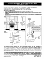
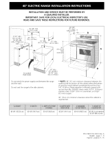
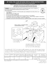
Clearances and Dimensions
1. Provide adequate clearances between the range and adjacent combustible surfaces.
2. Location--Check location where the ranae will be installed, Check for proper electrical supply, and the stability
of the floor.
3. Dimensions that are shown must beused. Given dimensions provide minimum clearance. Contact surface must
be solid and level.
FRONT
VIEW .......
. 30_
Minimum to
t,,-i ÷ _| Minimum to
wall on either " . cab nets on
side of range ®®/1"_-_ ®® 18 eitherside
above 36 height. _ _ of range.
SIDE
VIEW
i
÷13 "-I_
Maximum depth
for cabinets
above range top.
30" _ O'dearancebdowcookingtopandatreatofrange,
RANGE
OVERALL
DIMENSIONS
-- • 253/4"
Door Open \\ 29 7/g''_a_
Centerline
of range
All dimensions for electrical
_utlet location are maximum.
t
I II
i _" Dashed cubed area
1 shows where the e ectr ca
/
| outlet must be installed
I [.forflush to the wall installation
-_111"L._ •
/
1 i -° i
2-5/8" for models equipped
with warmer drawers"
3-1/2" for models equipped
with storage drawers
*30" MINIMUM CLEARANCE BETWEEN THE TOP OF THE COOKING SURFACE AND THE BOTTOM OF AN
UNPROTECTED WOOD OR METAL CABINET; OR 24" MINIMUM WHEN BOTTOM OF WOOD OR METAL CABINET IS
PROTECTED BY NOT LESS THAN 1/4" FLAME RETARDANT MILLBOARD COVERED WITH NOT LESS THAN NO. 28
MSG SHEET STEEL, 0.015" STAINLESS STEEL, 0.024" ALUMINUM OR 0.020" COPPER. 0" CLEARANCE IS THE
MINIMUM FOR THE REAR OF THE RANGE. FOLLOW ALL DIMENSION REQUIREMENTS PROVIDED ABOVE TO
PREVENT PROPERTY DAMAGE, POTENTIAL FIRE HAZARD, AND INCORRECT COUNTERTOP AND CABINET CUTS.
TO ELIMINATE THE RISK OF BURNS OR FIRE BY REACHING OVER HEATED SURFACE UNITS, CABINET STORAGE
SPACE LOCATED ABOVE THE SURFACE UNITS SHOULD BE AVOIDED. IF CABINET STORAGE IS TO BE
PROVIDED, THE RISK CAN BE REDUCED BY INSTALLING A RANGE HOOD THAT PROJECTS HORIZONTALLY A
MINIMUM OF 5" BEYOND THE BOTTOM OF THE CABINETS.
Fran_ais- Pages7-12
Espafiol- P_ginas13-18
PIN 316259200 (0104) 1

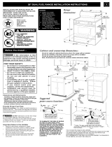
IMPORTANT SAFETY
INSTRUCTIONS
Iftheinformationinthismanualisnotfollowed
exactly, afire orelectricalshockmay result causingproperty
damage, personalinjuryor death.
• ALL RANGES
CAN TIP
• INJURYTO PERSONS
COULD RESULT
• INSTALL ANTI-TIP
DEVICE PACKED WITH
RANGE
• SEE INSTALLATION
INSTRUCTIONS
Important Notes to the Installer
1, Read all instructions contained in these installation
instructions before installing range.
2. Remove all packing material from the oven compartments
before connecting the gas and electrical supply to the
range,
3. Observe all governing codes and ordinances.
4. Be sure to leave these instructions with the consumer.
Important Note to the Consumer
Keep these instructionswithyourowner's guide for future
reference.
As whenusinganyappliancegeneratingheat, there are
certainsafetyprecautionsyou shouldfollow.These are
listedinthe Use& Care Manual. read itcarefully.
Besureyourrangeisinstalledandgroundedproperlyby
a qualified installer orservice technician.
Make sure the wall coverings around the range can
withstand the heat generated by the range.
Toeliminate the needto reach overthe surface elements,
cabinet storage space above the elements should be
avoided.
Before Starting
Tools You Will Need
For leveling legs and Anti-Tip Bracket:
Adjustablewrenchor channel lockpliers
5/16" Nutdriveror Flat Head Screwdriver
Electric Drill & 1/8" Diameter Drill Bit (Masonry Drill Bit if
installing in concrete)
For electrical supply connection:
1/4" & 3/8" Socket driver or Nutdriver _1]====_
Additional Materials You Wig Need
Power Supply Cord or
Copper Electrical Widng&Metal Conduit (for hardwiring)
Normal Installation Steps
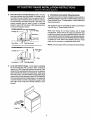
1. Anti-Tip Bracket Installation Instructions
Important Safety Warning
To reduce the risk of tipping of the range, the range mustbe
secured to the floor by properly installed anti-tip bracket and
screws packed with the range. Failure to install the anti-tip
bracket will allow the range to tip over if excessive weight is
placed on an open door or if a child climbs upon it. Serious
injury might result from spilled hot liquids or from the range
itself.
If range is ever moved to a different location, the anti-tip
brackets must also be moved and installed with the range.
Instructions are provided for installationinwood or cement
fastened to either the floor or wall. When installed tothe wall,
make sure that screws completely penetrate dry wall and are
secured inwood ormetal. When fastening tothe floor orwall,
be sure that screws do not penetrate electrical wiring or
plumbing.
A. Locatethe Bracket Using the Template- (Bracketmay
belocatedoneithertheleftorrightsideoftherange. Use
the informationbelowto locatethe bracketiftemplateis
notavailable). Mark the flooror wallwhere leftor right
sideoftherangewillbelocated. Ifrearofrangeisagainst
thewallornofurtherthan 1-1/4"from wallwhen installed,
you may usethe wall orfloor mount method. If molding
is installedand does not allow the bracket to fit flush
againstthewall,removemoldingormountbrackettothe
floor. Forwall mount,locate the bracketby placingthe
backedge ofthetemplate againstthe rear wall andthe
sideedge oftemplate onthemarkmadereferencingthe
sideofthe range. Place bracket ontop oftemplate and
marklocationofthe screwholesin wall. Ifraar ofrange
isfurther than 1-1/4"from thewallwhen installed,attach
brackettothe floor. Forfloor mount, Iocatethe bracket
byplacingbackedge ofthe template where the rear of
the rangewillbe located. Markthe locationofthescrew
holes, shown in template.
2

B,
Drill Pilot Holes and Fasten Bracket - Drilla 1/8"pilot
holewhere screwsareto be located. Ifbracket isto be
mountedtothewall,drillpilotholeatanapproximate20°
downwardangle. If bracketistobe mountedto masonry
orceramicfloors,drilla 5/32" pilothole 1-3/4"deep.The
screws provided may be used in wood or concrete
material. Usea 5/16" nut-driverorflathead screwdriver
to securethe bracketin place.
FASTEN BRACKET (W*_LOr FLOOrMOUNTING)
--_l 1<--1-1/4"Max.
Leveling Leg I
Mount
Floor Mount _ I--Anti-Tip Bracket
FASTEN BRACKET (FLOOR MOUNTING ONL'd
Leveling Leg --
N
FloorlM°unt _i LAntI'Tip Bracket
- More Than
1-1/4"
Wall
C. Level and Position Range - Level range by adjusting
the (4) levelinglegs with a wrench. Note: A minimum
clearanceof 1/8" is requiredbetween the bottomof the
rangeand thelevelinglegto allowroomfor thebracket.
Usea spiritleveltocheckyouradjustments.Sliderange
back into position. Visually check thatrear levelingleg is
inserted into and fullysecured by the Anti-Tip Bracket by
removing lower panel orstorage drawer. Formodelswith
a warmer drawer or broiler compartment, grasp the top
rear edge of the range and carefully attempt to tilt it
forward.
2. Electrical Connection Requirements
Thisappliancemustbe properlyinstalledand groundedbya
qualifiedtechnicianinaccordancewiththeNationalElectrical
CodeANSI/NFPA No.70-latest edition--andlocalelectrical
code requirements,
This appliance may be connected by means of permanent
"Hard Wiring" or "Power Supply Cord Kit."
When hard wiring, do not leave excess wire in range
compartment. Excess wire in the range compartment may
not allow the access cover tobe replaced properly, and could
create a potential electrical hazard if wires become pinched.
Connect only asinstructed under'_/IRING INSTRUCTIONS"
in section 4A or 4B. When using flexible conduit or range
cable use flex connector or range cable strain relief.
NOTE: Only usecopper wire inconnectiontoterminal block.
(17ram)
Range Side
%
%

2A.Models with Factory Connected Power
Supply Cord
NOTE: Some models may be equipped with a factory
connected three (3) conductorpowersupplycord,
Mobile home installations, new branch circuitinstallations
(1996NEC) or areas where local codes do not permit
grounding through neutral require afour (4) conductor power
supply cord kit rated at 125/250 volts minimum and marked
for use with ranges. See Range Connection Opening Size
Chart for cord kit ampere rating information. Terminals on
end of wires must be either closed loop or open-end spade
lugs with upturned ends.
2B.Models Requiring Power Supply Cord Kit
RISK OF FIRE OR ELECTRICAL SHOCK MAY OCCUR IF
AN INCORRECT SIZE RANGE CORD KIT IS USED, THE
INSTALLATION INSTRUCTIONS ARE NOT FOLLOWED
OR STRAIN RELIEF BRACKET IS DISCARDED.
This appliance may be connected by means of a power
supply cord. Only a power supply cord kit rated at 125/250
volts minimum, and marked for use with ranges shall be
used. See chart on page 3 for cord kit ampere rating
information. Cord must have either three (3) or four (4)
conductors. Terminals on end of wires must be either closed
loop or open-end spade lugs with upturned ends. Cord must
have strain relief clamp.
See section4Afor 3-wire or section4B for4-wire connection.
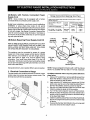
3. Electrical Connection to Range
The rear access cover must be removed. To remove,loosen
center screw (one screw) and remove access cover. The
terminal block will then be accessible.
Cover
Rear
of Range
Range Connection Opening Size Chart
Supply Cord Kit ampere rating information. See serial plate on range for
kilowatt rating data.
See Serial Plate on Range for Cord Kit
KW Rating Ampere
Rating
120/240 Volts 120/208 Volts
8.8-16.5 IGV 7.9-12.5 ION 40/50 Amp
t6.6-22.5 KW 12.6-18.5 KVV 50Amp
Diameter (inches) of Range
connection Opening
Permanent
Cord Kit Wirinq
1-3/8 in. 1-1/8 in.
1-3/8 in. 1-3/8 in.
1-1/8" Dia.
Knockout
(See Chart)
Mounting_
Plate_
1-3/8" Dia. _- •
Hole
(See Chart)
718"Dia. 4"
Hole
(See Chart)
Pocket
for Cable
Mounting Plate
f
NOTE: Range isshipped from factory with 1-3/8"dia. hole as
shown. To use either 7/8" dia. hole or 1-1/8" dia. knockouts:
If a different diameter hole is required, please follow the
steps below:
1. Using a 1/4" socket ddver, remove eight (8) screws from
Rear Wall Shield to release from the unit (as shown).
Save the screws for step #7 below.
2. Again using the 1/4" socket driver, remove one (1) blunt
point screw used to secure the Cable Mounting Plate to
the Rear Wall Shield. Save the screws for step #6.
3. Remove the Cable Mounting Plate from the Rear Wall
Shield by sliding the plate out of the pockets.
4. Ifa 1-1/8" dia. hole is required, "punch-out" the knockout.
5. Rotate the plate 180 degrees so that the desired hole is
placed on top of the opening located on the bottom flange
of the Rear Wall Shield.
6. Slide the Cable Mounting Plate into the RearWall Shield.
Re-secure using the blunt point screw removed from step
#2 above.
7. Reassemble the Rear Wall Shield tothe unit using eight
(8) screws removed from step #1 above.
4

4A. Wiring Instructions (3-Wire Connection)
1. Remove the three (3) loose nuts on the terminal block
usinga 3/8" nut driveror socket.
NOTE: Do not loosenthenuts which secure the factory
installed range wiring to the terminal block. Electrical
failure or loss of electrical connection may occur if nuts
are loosened.
2. Using the nuts removed in step 1, connect the cable or
copper power supply cord to the three (3) studs on the
terminal block, aslocal codes require. The neutral (white)
wire or center wire must be connected to the center
terminal.
3. Make sure all nuts are tightened securely.
4. Replace the rear access cover.
GROUNDING INSTRUCTIONS:
A ground link is installed on this range which connects the
center terminal of the terminal block (neutral) to the chassis.
The ground link is not visible in the picture below but is
connected to the range by the center, lowest screw (shown in
picture below). The ground link must not be removed unless
national or local codes do not permit use of ground link.
NOTE: If the ground link is removed for any reason, a
separate ground wire must be connected to the separate
ground screw attached to the range chassis and to an
adequate ground source.
3-Wire
Connection
4B. Wiring Instructions (4-Wire Connection)
Ifconnectingtoa 4-wireelectricalsystem(newbranch-circuit
or mobilehome requires4 wire connection):
1. Remove the three (3) loose nuts on the terminal block
usinga 3/8" nutdriverorsocket. Fromthe centerstudon
theterminalblock,removethesecondnutandthecopper
groundstrap. Replacethenutthatheldthegroundstrap
to the terminalblock.
NOTE: Do not loosen the second nut on line 1 or line2
which secure the factory installed range wiring to the
terminal block. Electrical failure or loss of electrical
connection may occurif nuts are loosened.
2. Remove the ground screw torelease the copper ground
strap from the appliance.
3. Discard the ground strap. Connect the ground wire
(green) of the copper power supply cord to the frame of
the appliance with theground screw, using thesame hole
in the frame where the ground strap was removed.
4. Using the nuts removed in step 1, connect the neutral
(white) wire ofthe copper power supply cordto the center
silver colored stud on the terminal block.
5. Connect the final two (2) wires to the outer studs on the
terminal block.
6. Make sure all nuts are tightened securely.
7. Replace the rear access cover.
4-Wire
Connection
Terminal
Terminal
\
3-Wire Copper Power Supply Cord.
To Fused Disconnect Box or Approved
Wiring Device for Copper Supply Cord.
4-Wire Copper Power Supply Cord.
To Fused Disconnect Box or Approved
Wiring Device for Copper Supply Cord.
Insulated
Copper
Ground
Wire

Model and Serial Number Location
The serial plate is located on the right-handsurface ofthe
oven front frame at the storage or warmer drawer; or the
lower panel area.
When ordering parts foror making inquires about your range,
always be sure to includethe model and serial numbers and
a lot number or letter from the serial plate on your range.
Your serial plate also tells you the Kilowatt rating (power
requirements) and Voltage ratings
Care, Cleaning and Maintenance
Refer to the Use & Care Manual for cleaning instructions.
If removing the range is necessary for cleaning or
maintenance, disconnect the electrical power supply. If the
electricalsupply isinaccessible,lift the unitslightly atthe front
and pull out away from the wall. Pull only as far as necessary
to disconnect the electrical supply. Finish removing the unit
for servicing and cleaning. Reinstall in reverse order making
sureto level the range end check electrical connections. See
pages 2 and 3 for proper anchoring instructions.
Before You Call for Service
Read the"Before You Call" andoperatinginstruction sections
in your Use & Care Manual. It may save you time and
expense. The list includescommon occurrences that are not
the result of defective workmanship or materials in this
appliance.
Refer to the warranty inyourUse & Care Manual for ourtoll-
free service number and address. Please call orwrite if you
have inquiries about your range product and/or need toorder
parts.
• o
®® f ®®
\ .... ]
;]};! ] ;$H _i F } &%%
Serial plate location
Open storage or warmer drawer,
or remove lower panel
(on some models)
-
 1
1
-
 2
2
-
 3
3
-
 4
4
-
 5
5
-
 6
6


Ask a question and I''ll find the answer in the document
Finding information in a document is now easier with AI
Related papers
-
Tappan TEF317AWC Installation guide
-
Kenmore Elite 30" Installation guide
-
Crosley CRE3880GQQA Installation guide
-
Kenmore Elite GLEF379DBB Installation guide
-
Kenmore Elite FEFL64FSA Installation guide
-
Frigidaire FFEF3018LS Installation guide
-
Kenmore Elite FPCF3091LFD Installation guide
-
Frigidaire GCRI3058AF Installation guide
-
Frigidaire 96197 Installation guide
-
Other documents
-
 Kenmore Elite 79099613702 Installation guide
-
Electrolux EI30EF55GSB Installation guide
-
 Kenmore Elite 79079389400 Installation guide
-
Electrolux EW30DF65GSB Installation guide
-
Kenmore Elite 79078509011 Installation guide
-
Electrolux EW3LDF65GBA Installation guide
-
 Kenmore Elite 79046623501 Installation guide
-
Kelvinator KEF355XSB Installation guide
-
Bosch HES3053U/10 Installation guide
-
GE JXCH1 Installation guide


