Page is loading ...

Parts and Instruction Manual
290 Series Stainless Steel Vacuum
4 & 6 Gallon

Parts
and Instruction Manual
This manual is furnished with each new MINUTEMAN 290 Vacuum. This provides the neces-
sary operating and preventive maintenance instructions. Operators must read and understand
this manual before operating or servicing this machine.
This machine was designed to give you excellent performance and efficiency. For best results
and minimal cost, please follow the general guidelines below:
• Operate the machine with reasonable care.
• Follow the manufacturers suggested maintenance instructions as provided in this booklet.
• Use original Minuteman supplied parts.
Model No.
115V
230V
Power
Tank Size
Dry Capacity
Wet Capacity
Airflow
Waterlift
Decibel Rating
Weight
C29485-01
C29486-01
1.25 hp (1000W)
4 gal (15 ltrs)
.21ft³ (.006m³)
N/A
95 cfm (2.7m³/min)
85 in (2159mm)
68 db
25 lbs (11 kg)
C29685-01
C29686-01
1.25 hp (1000W)
6 gal (23 ltrs)
.46ft³ (.013m³)
4.5 gal (17 ltrs)
95 cfm (2.7m³/min)
85 in (2159mm)
74 db
26lbs (12 kg)

Parts
and Instruction
M
anual

Parts
and Instruction Manual
Table of Contents
INSPECTION........................................................................................................................................ 2
ELECTRICAL....................................................................................................................................... 2
115 Volt ........................................................................................................................................... 2
240 Volt ........................................................................................................................................... 2
GROUNDING INSTRUCTIONS ........................................................................................................... 2
USER MAINTENANCE INSTRUCTIONS ............................................................................................ 3
CLOTH BAG & HOSE ASSEMBLY ..................................................................................................... 3
CORD STORAGE ................................................................................................................................ 3
Exploded Views .................................................................................................................................. 7
Bag Assembly ................................................................................................................................. 7
Lid Assembly (Dry Only).................................................................................................................. 8
Lid Assembly (Dry Only) BOM......................................................................................................... 9
Lid Assembly (Wet/Dry)................................................................................................................. 10
Lid Assembly (Wet/Dry) BOM........................................................................................................ 11
Tank Assembly .............................................................................................................................. 12
Industrial Tools and Accessories.................................................................................................... 13
Model C29485-01, C29486-01 ......................................................................................................13
Model C29685-01, C29686-01 ......................................................................................................14
Wiring Diagrams ............................................................................................................................... 15
Minuteman International Made Simple Commercial Limited Warranty........................................ 16

Parts and Instruction Manual
Page 1
FOR COMMERCIAL USE ONLY
IMPORTANT SAFETY INSTRUCTIONS
When using an electrical appliance, basic precautions should always be followed, including the
following:
READ ALL INSTRUCTIONS BEFORE USING
WARNING - To reduce the risk of fire, electric shock, or injury:
• Do not leave appliance when plugged in. Unplug from outlet when not in use and before
servicing, cleaning or maintaining.
WARNING: C29685-01 / C29686-01 Wet & Dry
To reduce the risk of electric shock - Do not expose to rain. Store indoors.
WARNING: C29485-01 / C29486-01 Dry Only
Electric shock could occur if used on wet surfaces. Do not expose to rain and store indoors.
• Do not allow to be used as a toy. Close attention is necessary when used by or near children.
• Use only as described in this manual. Use only manufacturer’s recommended attachments.
• Do not use with damaged cord or plug. If appliance is not working as it should, has been
dropped, damaged, left outdoors, or dropped into water, return it to a service center.
• Do not pull or carry by cord, use cord as a handle, close a door on cord, or pull cord around
sharp edges or corners. Do not run appliance over cord. Keep cord away from heated surfaces.
• Do not unplug by pulling on cord. To unplug, grasp the plug, not the cord.
• Do not handle plug or appliance with wet hands.
• Do not put any object into openings. Do not use with any opening blocked; keep free of dust,
lint, hair, and anything that may reduce air flow.
• Keep hair, loose clothing, fingers, and all parts of body away from openings and moving parts.
• Do not pick up anything that is burning or smoking, such as cigarettes, matches, or hot ashes.
• Do not use without dustbag and/or filters in place.
• Turn off all controls before unplugging.
• Use extra care when cleaning on stairs.
• Do not use to pick up flammable or combustible liquids such as gasoline or use in areas where
they may be present.
• Connect to a properly grounded outlet only. See grounding instructions.
SAVE THESE INSTRUCTIONS

Parts and Instruction Manual
Page 2
INSPECTION
Carefully unpack and inspect your machine for shipping damage. Each unit is tested and thoroughly
inspected before shipment, and any damage is the responsibility of the delivery carrier who should
be notified immediately.
ELECTRICAL - 115 Volt
This machine is designed to operate on a standard 15 amp. 115 volt, 60 hz, AC circuit. Voltages
below 105 volts AC or above 125 volts AC could cause serious damage to the motor.
ELECTRICAL - 240 Volt
This machine is designed to operate on a standard 10 amp. fused 230 volt, 50 hz, AC circuit.
WARNING
Electric motors can cause explosions when operated near explosive materials or vapors. Do not
operate this machine near flammable materials such as solvents, thinners, fuels, grain dust, etc.
GROUNDING INSTRUCTIONS
This appliance must be grounded. If it should malfunction or breakdown, grounding provides a
path of least resistance for electric current to reduce the risk of electric shock. This appliance is
equipped with a cord having an equipment-grounding conductor and grounding plug. The plug
must be plugged into an appropriate outlet that is properly installed and grounded in accordance
with all local codes and ordinances.
DANGER - Improper connection of the equipment-grounding conductor can result in a risk
of electric shock. Check with a qualified electrician or service person if you are in doubt as to
whether the outlet is properly grounded. Do not modify the plug provided with the appliance — if
it will not fit the outlet, have a proper outlet installed by a qualified electrician.
This appliance is for use on a nominal 120 volt circuit and has a grounding plug that looks like the
plug illustrated in Sketch A below. Make sure that the appliance is connected to an outlet having
the same configuration as the plug. No adapter should be used with this appliance.
For equipment rated 150-250 volts: If the machine is provided with an attachment plug as shown
in Sketc B, it is intended for use on a 240 volt (nominal) circuit. No adapter is available for this
plug.

Parts and Instruction Manual
Page 3
USER MAINTENANCE INSTRUCTIONS
All service and repair should be performed by qualified vacuum service representative or electrician.
No user serviceable components are employed in the electrical vacuum lid head assembly. No
lubrication of the motor is required.
CLOTH BAG & HOSE ASSEMBLY
Cloth bag and hose assembly are user maintenance items and can be replaced when worn out.
Cloth bags can be maintained by blowing dust off of the bag and then laundering. Cloth bags
should be completely dryed before re-installing into machine. For optimum performance, empty
and clean filter bag regularly. A clogged and dirty bag restricts the flow of air and results in
reduced vacuum. Wet & Dry Models only: Remove the dry dust filter bag. Check the automatic
shut-off to be certian it is working properly. The hose assembly can be maintained by wiping off
with a dampened cloth of mild liquid soap and water, then allowed to dry.
CORD STORAGE
While not in use storage can be accomplished by winding cord around motor lid assembly. Cord
should be completely unwound from lid assembly during operation.
• Do not use with damaged cord or plug. If appliance is not working as it should, has been
dropped, damaged, left outdoors, or dropped into water, return it to service center.
• Do not pull or carry by cord, use cord as handle, close a door on cord, or pull cord around sharp
edges or corners. Do not run appliance over cord. Keep cord away from heated surfaces.
• Do not unplug by pulling cord. To unplug, grasp the plug, not the cord.
• Do not handle plug or appliance with wet hands.
Always unplug the machine when removing the motor head off the tank. This equipment should
be stored indoors and not exposed to rain.

Parts and Instruction Manual
Page 4

Parts and Instruction Manual
Page 5

Parts and Instruction Manual
Page 6

Parts and Instruction Manual
Page 7
Exploded Views
Bag Assembly
Item Part No. Qty. Description
1 760244 1 Bag Ring 4/6 PV Black
2 805043 1 Bag Only 4G
2A 805040 1 Bag Only 6G
3 805044 1 Cloth Bag Assy 4G
3A 805041 1 Cloth Bag Assy 6G

Parts and Instruction Manual
Page 8
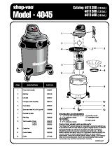
Lid Assembly (Dry Only)

Parts and Instruction Manual
Page 9
Item Part No. Qty. Description
1 290017 2 Molded Vac Motor Gasket
2 290031 1 Lid Gasket 294/6 Diecut
3 380005 2 Carbon Brush Replacement (ECM)
3A 380028 2 Carbon Brush Replacement
4 381001-4 1 Vac Motor 120V (ECM)
4A 381044-2 1 Vac Motor 240VAC w/Male QC Term
5 460001 1 Handle Basic 460 Black
6 460101 1 Motor Cap Black
7 460106 1 Bag Guard Black
8 460116 1 Motor Pan Assembly 294/6
9 711124 3 SCR-ST-B 10 x .37 NI
10 711125 3 SCR-ST-B 10 x .50 NI
11 711128 4 SCR-ST-B HI/LO 8 x .62 Zinc
12 711160 1 SCR HI/LO #10 x 5/8 Zinc
13 711161 8 SCR HI/LO #10 x 3/4 Zinc
14 711162 2 SCR HI/LO #10 x 1 1/2 Zinc
15 711553 1 WSR-Internal Lock #10
16 715015 1 Decal, Warning 1.25x2.75
17 740705 1 Cord 18GA-3 40FT Grey
17A 740600 1 Cord European F3 G1.5MM 50FT B
18 809754 1 Switch-Rocker
18A 809754CE 1 Switch-Rocker
19 831801 1 Receptacle
20 831801-1 1 Receptacle Clip
21 832197 1 Felt Upper Dome
22 832198 1 Felt Outer Dome
23 832201 1 Motor Lid Cover 294 Dry
24 832219 1 Diffuser Foam 27”
25 832637 1 Motor Hold Down 294
26 833237 1 Strain Relief w/ Nut
CE Model Only
27 710328 2 SCR-MC 8-32 x .37 Zinc
28 711372 2 Nut-Nyloc 8-32
29 740613 1 Capacitor Assembly .1UF
30 742254-1 1 Torroid Assembly w/Wire Assy
31 742391 1 RFI Filter
32 744407 1 Wire Assy Grn/Yel 8.00”
33 832107 1 RFI Bracket 290 Series Vac
*** 294110 1 Lid Assy. Complete 115V Dry
*** 294220CE 1 Lid Assy. Complete 294 230V CE Dry
Lid Assembly (Dry Only) BOM

Parts and Instruction Manual
Page 10
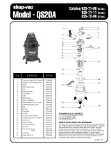
Lid Assembly (Wet/Dry)

Parts and Instruction Manual
Page 11
Item Part No. Qty. Description
1 290017 2 Molded Vac Motor Gasket
2 290031 1 Lid Gasket 294/6 Diecut
3 290032 1 Dome Seal 296
4 380001-4 1 Vac Motor 120V (ECM)
4A 380054-1 1 Vac Motor 240VAC w/Male QC Term
5 380005 2 Carbon Brush Replacement (ECM)
5A 380028 2 Carbon Brush Replacement
6 380064 1 Ring, Foam
7 381020 1 Cord 16GA-3 50FT Med Grey
7A 740600 1 Cord European F3 G1.5MM 50FT B
8 460001 1 Handle Basic 460 Black
9 460100 1 Motor Lid Cover Black
10 460101 1 Motor Cap Black
11 460104 1 Motor Hold Down Plate Black
12 460105 1 Float Cage Black
13 460116 1 Motor Pan Assembly 294/6
14 460117 1 Float Assembly 290-6
15 711124 1 SCR-ST-B 10 x .37 NI
16 711125 3 SCR-ST-B 10 x .50 NI
17 711128 4 SCR-ST-B HI/LO 8 x .62 Zinc
18 711160 1 SCR HI/LO #10 x 5/8 Zinc
19 711161 11 SCR HI/LO #10 x 3/4 Zinc
20 711162 2 SCR HI/LO #10 x 1 1/2 Zinc
21 711553 1 WSR-Internal Lock 10
22 715009 1 Decal, Warning to Avoid
23 715501 1 Decal Made in USA
24 809754 1 Switch Rocker
24A 809754CE 1 Switch Rocker CE
25 828893 1 Rivet Bap KTR64BX
26 833237 1 Strain Relief w/ Nut
CE Models Only
27 710355 2 SCR-MC RD HD10-32 x .50 Zinc
28 711350 2 Nut-Nyloc 10-32
29 742254-1 1 Torroid Assembly w/Wire Assy
30 742393 1 RFI Filter
31 742394 1 Capacitor Assembly .15 UF
32 744407 1 Wire Assy 16G Grn/Yel 8.00”
*** 296115 1 Lid Assy Comp 115V
*** 296230CE 1 Lid Assy Comp 296 230V CE
Lid Assembly (Wet/Dry) BOM

Parts and Instruction Manual
Page 12
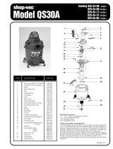
Tank Assembly
Item Part No. Qty. Description
1 390087 1 Gasket Diecut VNN
2 390110 1 Intake Assembly Aluminum
3 460113 1 Caster Bracket (4 Gal)
3A 460113MCH 1 Caster Bracket (6 Gal)
4 460118 4 Caster
5 710530 1 SCR-MC 8-32x.50 BRS
6 711372 1 Nut-Nloc 8-32
7 711503 4 Flat Washer #10
8 711584 3 Washer #10
9 711915 4 Rivet-Tube .19x.28 NI PL
10 712066 3 SCR-ST-Pan HD-AB 10x1.25 Zinc
11 712638 2 Hex Nut 10/24 SS Nyloc
12 712764 3 Washer SS #10
13 712824 2 SCR-MC 10-24x.75 Truss HD ST
14 715383 1 Decal-MMN 1x6.88 Lt Gry
15 750118 1 Intake Asy Tube 4 Gal
16 761054 2 Latch
17 900014 1 Tank 6 Gal SS High Intake
17A 900109 1 Tank 4 Gal SS Low Intake
18 900035 1 Deflector Intake 6 Gal
*** 290006 1 Tank Asy 6G SS HI DF&WB
*** 290008 1 Tank Asy 4Gal SS Comp

Parts and Instruction Manual
Page 13
A
B
C
D
E
F
Industrial Tools and Accessories
Model C29485-01, C29486-01
829563 Dust Brush Complete
829562 Crevice Tool
1 1/4” (32 mm)
829565MCH Wand Tube
(2 required)
829849 Hose Assy. 1-1/4 x 8 (32 mm x 2.4 m)
390013 Cuff
762241 Hose
829566 Tube Handle
829561 Combination Floor Tool
829564 Upholstery Tool
Part No. Description

Parts and Instruction Manual
Page 14
A
B
C
D
E
F
G
Industrial Tools and Accessories
Model C29685-01, C29686-01
Part No. Description
800083 3" Rd. Dust Brush Complete
133249 Dust Brush HSG 3"
800084 Bristle Insert 3"
808023 Adapter
800035 12" Crev Tool Complete
290000 Wand Assy. 1-1/2, Complete
290001 Upper Wand
290002 Lower Wand
800317 Hose Assy. 1-1/2 x 10'
390014 1-5” Molded Hose Intake
801044 Hose
800605 14" Squeegee, Complete
712088 SCR #10 HILO
800615 14" Retaining Strip
808648 Nozzle, Squeegee
500295 Blade Squeegee
500296 Blade Squeegee Reinforcement
800124 5" Tool Only Without Insert
731 Bristle Insert Replacement
829561 Combination Floor Tool

Parts and Instruction Manual
Page 15
Wiring Diagrams

Minuteman International, Inc. warrants to the original purchaser/user that the product is free from defects in
workmanship and materials under normal use. Minuteman will, at its option, repair or replace without charge, parts
that fail under normal use and service when operated and maintained in accordance with the applicable operation and
instruction manuals. All warranty claims must be submitted through and approved by factory authorized repair
stations.
This warranty does not apply to normal wear, or to items whose life is dependent on their use and care, such as belts,
cords, switches, hoses, rubber parts, electrical motor components or adjustments. Parts not manufactured by
Minuteman are covered by and subject to the warranties and/or guarantees of their manufacturers. Please contact
Minuteman for procedures in warranty claims against these manufacturers.
Special warning to purchaser -- Use of replacement filters and/or prefilters not manufactured by Minuteman or its
designated licensees, will void all warranties expressed or implied. A potential health hazard exits without original
equipment replacement.
All warranted items become the sole property of Minuteman or its original manufacturer, whichever the case may be.
Minuteman disclaims any implied warranty, including the warranty of merchantability and the warranty of fitness for a
particular purpose. Minuteman assumes no responsibility for any special, incidental or consequential damages.
This limited warranty is applicable only in the U.S.A. and Canada, and is extended only to the original user/purchaser
of this product. Customers outside the U.S.A. and Canada should contact their local distributor for export warranty
policies. Minuteman is not responsible for costs or repairs performed by persons other than those specifically
authorized by Minuteman. This warranty does not apply to damage from transportation, alterations by unauthorized
persons, misuse or abuse of the equipment, use of non-compatible chemicals, or damage to property, or loss of
income due to malfunctions of the product.
If a difficulty develops with this machine, you should contact the dealer from whom it was purchased.
This warranty gives you specific legal rights, and you may have other rights which vary from state to state. Some
states do not allow the exclusion or limitation of special, incidental or consequential damages, or limitations on how
long an implied warranty lasts, so the above exclusions and limitations may not apply to you.
Cord Electric Group………. Three years parts, two years labor, ninety days travel (Not to exceed two hours)
Exceptions………. Port-A-Scrub, one year parts, six months labor
MPV 13, one year parts
MPV 14 and 18, two years parts, one year labor
RapidAir blower, one year parts, one year labor
Explosion-Proof Vacuum, one year parts, one year labor
Pneumatic Vacuums, three years parts, one year labor
EX 12 and EX12H, one year parts, one year labor
Battery Operated Group….. Three years parts, two years labor, ninety days travel
(Not to exceed two hours)
Exceptions……Sweepers, one year parts, one year labor, ninety days travel
(Not to exceed two hours)
Internal Combustion Group….One year parts, one year labor, ninety day travel
(Not to exceed two hours)
Replacement Parts……………..Ninety days
Batteries………………………….0-3 months replacement, 4-12 months pro-rate
Polypropylene Plastic Tanks…Ten years, no additional labor
111 South Rohlwing Road · Addison, Illinois 60101 USA
Phone 630- 627-6900 · Fax 630- 627-1130
E-Mail, www.minutemanintl.com
A Member of the Hako Group
Minuteman International Made Simple Commercial Limited Warranty
987216
Rev B 08/07
/