Mega Lite COLORPAC 150N Owner's manual
- Category
- Floodlights
- Type
- Owner's manual

USER MANUAL
Table of Contents
Safety Information…………………………………………………..…3
Specifications………………………………………………………….. 4
Main Power Connection…………………………………………….. 5
IR Controller………….……………………………………………...... 5
Main Control Menu......................................................................... 6
DMX Profile.................................................................................... 8
Wireless DMX Set Up…………………………………………………10
Rigging the Fixture……………………………...……………………..11
Cleaning & Maintenance.................................................................11
Parts List.........................................................................................11


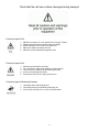
Check that the unit has not been damaged during transport
Protection Against Fire
1. Maintain a minimum of 1 foot distance from any type of flame.
3. Replace fuse only with the specified type and rating.
4. Do Not install the unit to close to a heat source.
5. Make sure cable are properly secured
6. Maximum surface operating temperature 140º.
Protection Against Fire
1. Disconnect power before servicing.
2. For connection to main power supply proceed to page 5.
3. This unit must be earthed. (electronically grounded)
4. Ip 64 do not submerge into water.
5. Do not leave fixture on for long periods of time.
Protection Against Mechanical Hazards
1. Use safety chain when hanging unit.
2. Use quality clamps or bolts when positioning unit
3. Do not open unit while it is on, risk of electrical shock.
3

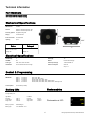
Technical Information
4
7310– Color PAC 150 N Black Housing
7311– Color PAC 150 N White Housing
Mechanical Specifications
Fixture Packaged
Size: 7” x 5.75” x 2.55”
Weight: 3lb
Electrical Specifications
DMX 512 Protocol via W-DMX
DMX Modes: Mode 1 3 Channels Red, Green, Blue
Mode 2 4 Channels Red, Green, Blue, White
Mode 3 5 Channels Dimmer, Red, Green, Blue, White
Mode 4 7 Channels Dimmer, Red, Green, Blue, White, Strobe, Macro
Mode 5 8 Channels Dimmer, Red, Green, Blue, White, Strobe, Macro, Dimming Curve
Control Options: IR Controller (included)
Control & Programming
DMX Wireless: W-DMX
Thermal: Maximum ambient temperature 104°
Maximum surface temperature 140°
Fastening System: Single Mounting Yoke
Display: Touch Sensitive
Power connection: DC Connection
Ip Rating; Ip 64
LED Quantity: 1 LED Angle: 10°
LED Watt: 15 Ballast: External Power Supply
Color Type: Red, Green , Blue and White Power Input Voltage: 110V-240 50/60 Hz
LED Lifetime: *60 to 100 thousand hours Average Power Consumption Watts: 10
Amps: .17
Part Numbers
7”
2.55”
5.75”
* Average expected LED life per LED manufacture
Size: 10.5” X 8.5” X 4.75”
Weight: 5 lb
Battery Life
Average Battery Life:
High Mode: Low Mode:
Full Color: 4:45 Hr Full Color: 8:10 Hr
Color Fading: 8:00 Hr Color Fading: 14:00 Hr
Single Color: 15:00 Hr Single Color: 25:40 Hr
Battery Cycle Life: 500 Recharges
Battery Type: Li-Ion 5200mAh 11.1V
Photometrics
Photometrics at 10Ft

5
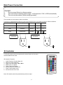
Main Power Connection
Caution!
1. Do not connect fixture to a dimmer system.
2. This unit has Auto switching power supply. It will respond to 110V or 220V automatically
3. This unit must be earthed. (electronically grounded)
The occupation of the connection-cable is as follows:
This fixture is equipped with an electronic power supply that will let the unit operate from 90V to 240V from 50Hz to
Cable (USA) Cable (EU) Pin 110V
Black Brown
White
Green
Light Blue
Yellow/Green
Live
Neutral
Ground
L
N
220V
L
L
110V
Connection
220V
Connection
L N
L L
IR Controller
Note: IR Controller should be pointed directly at fixture output.
IR Controller Functions
1. On/Off Function= Red On, Black Off
2. Dimmer Function=Up/Down
3. Single Color= Red, Green, Blue, White
4. Mixed Color= 12 options
5. Flash= Fast Color Change
6. Strobe= Strobe the sected color
7. Fade= Fade between colors
8. Smooth=Smooth Color Fade
To Enter IR control mode you must press On. And the fixture can’t be set to
Wireless DMX Control mode

Display Menu
6
The control board on the fixture is your interface to access and control
all the functions on the unit. Its digital display gives you a code view of
the options and functions. The following will explain each function and
its options.
CONTROL BOARD
DMX Address
Press Enter to select the DMX start channel use the up/down keys, display will be flashing once you have selected
the desired start channel Press Enter to confirm display will stop flashing.
DMX Address
Red Dimmer
Green Dimmer Blue Dimmer
Fade
DMX Mode
1-512
0-255 0-255
0-255
0-99
Strobe
0-99
DMX Mode
This function allows you to select the mode in witch you want to control the fixture. Press Enter use the up/down keys to
select desired DMX mode settings. Press Enter to confirm the settings.
White Dimmer
0-255
3,4,5,7,8-Ch
Display Screen
0F10,30,60 or 90
Color Jump
0-99
Use the Menu Button to select Menu options
Dimming Mode
0-4
Power Save
Hi,Low
Display Lock
Off,On
Software
Ve
Fade Scroll
This function allows you to fade the LED’s from one color to another. Press Enter use the up/down keys to select de-
sired fade speed settings from 0 to 99. Press Enter to confirm the settings.
Color Jump
This function allows you to Switch Colors LED’s from one color to another. Press Enter use the up/down keys to select
desired fade speed settings from 0 to 99. Press Enter to confirm the settings.
3CH Mode R,G,B
4CH Mode R,G,B,W
5CH Mode Dimmer,R,G,B,W
7CH Mode Dimmer,R,G,B,W, Strobe, Macro
8CH Mode Dimmer,R,G,B,W, Strobe, Macro, Dimming Curve
ID

7
Flash
This function allows you to strobe all the LED’s. Press Enter use the up/down keys to select desired strobe speed set-
tings from 0 to 99. Press Enter to confirm the settings.
White Dimmer
This function allows you to dim up or down the white LED’s . Press Enter use the up/down keys to select desired dim-
mer settings. Press Enter to confirm the settings.
Red Dimmer
This function allows you to dim up or down the red LED’s . Press Enter use the up/down keys to select desired dimmer
settings. Press Enter to confirm the settings.
Green Dimmer
This function allows you to dim up or down the green LED’s . Press Enter use the up/down keys to select desired dim-
mer settings. Press Enter to confirm the settings.
Blue Dimmer
This function allows you to dim up or down the blue LED’s . Press Enter use the up/down keys to select desired dimmer
settings. Press Enter to confirm the settings.
Display Screen
This function allows you to set the display turn off time. Press Enter use the up/down keys to select desired turn off time
settings from 10,30,60 and 90 seconds. Press Enter to confirm the settings.
Dimming Mode
This function allows you to change dimming speeds all the LED’s. Press Enter use the up/down keys to select desired
dimming speed settings from 0 to 4 (0 fastest 4 slowest). Press Enter to confirm the settings.
Power Save
This function allows you to place the fixture on power save mode for extending the battery life. Press Enter use the up/
down keys to select desired intensity output from Hi to Low. Press Enter to confirm the settings.

8
DMX Profile
Lock
This function allows you to lock the fixture display. Press Enter use the up/down keys to select desired strobe speed
settings from Off to On. Press Enter to confirm the settings. To unlock press and hold enter and down for 3 seconds.
Software Version
This function informs you software version the units is operating under.
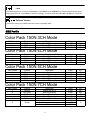
Color Pack 150N 3CH Mode
DMX Chanel Function Description Value Init
1 LED Color Red LED intensity 0-255 255
2 LED Color Green LED Intensity 0-255 255
3 LED Color Blue LED Intensity 0-255 255
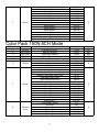
Color Pack 150N 4CH Mode
DMX Chanel Function Description Value Init
1 LED Color Red LED intensity 0-255 255
2 LED Color Green LED Intensity 0-255 255
3 LED Color Blue LED Intensity 0-255 255
4 LED Color White LED Intensity 0-255 255
Color Pack 150N 5CH Mode
DMX Chanel Function Description Value Init
1 Dimmer Dimmer 0-255 255
1 LED Color Red LED intensity 0-255 255
2 LED Color Green LED Intensity 0-255 255
3 LED Color Blue LED Intensity 0-255 255
4 LED Color White LED Intensity 0-255 255
Color Pack 150N 7CH Mode
DMX Chanel Function Description Value Init
1 Dimmer Dimmer Off to Full 0-255 255
2 LED Color Red LED intensity 0-255 255
3 LED Color Green LED Intensity 0-255 255
4 LED Color Blue LED Intensity 0-255 255
5 LED Color White LED Intensity 0-255 255
No Function 0-1
6 Strobe
Strobe (slow to fast) 2-196
0
Random Strobe (slow to fast) 197-255

No Function 0-1
Color fade All (slow to fast) 2-19
Color Snap All (slow to fast) 20-39
Random Color Snap (slow to fast) 40-59
Red fade (slow to fast) 60-79
Green fade (slow to fast) 80-99
Blue fade (slow to fast) 100-119
7 Macro
White fade (slow to fast) 120-139
0
Macro Effect 1 140-159
Macro Effect 2 160-179
Macro Effect 3 180-199
Macro Effect 4 200-219
Macro Effect 5 220-229
Macro Effect 6 230-249
Macro Effect 7 250-255
Color Pack 150N 8CH Mode
DMX Chanel Function Description Value Init
1 Dimmer Dimmer Off to Full 0-255 255
2 LED Color Red LED intensity 0-255 255
3 LED Color Green LED Intensity 0-255 255
4 LED Color Blue LED Intensity 0-255 255
5 LED Color White LED Intensity 0-255 255
No Function 0-1
6 Strobe
Strobe (slow to fast) 2-196
0
Random Strobe (slow to fast) 197-255
No Function 0-1
Color fade All (slow to fast) 2-19
Color Snap All (slow to fast) 20-39
Random Color Snap (slow to fast) 40-59
Red fade (slow to fast) 60-79
Green fade (slow to fast) 80-99
Blue fade (slow to fast) 100-119
7 Macro
White fade (slow to fast) 120-139
0
Macro Effect 1 140-159
Macro Effect 2 160-179
Macro Effect 3 180-199
Macro Effect 4 200-219
Macro Effect 5 220-229
Macro Effect 6 230-249
Macro Effect 7 250-255
Use Display Setting 0-5
Dimming 0 6-55
8 Dimming
Dimming 1 56-105
0
Curve
Dimming 2 106-155
Dimming 3 156-205
Dimming 4 206-255
9

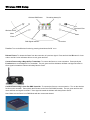
Wireless DMX Setup
Wireless DMX Status
Remaining battery life
Wireless ID Set
Up
Down
IR receiver
Enter
Menu
Wireless On/Off
Release Fixture: To release the fixture from the connection of a previous signal. Press and hold the ID button for 3 sec-
onds or until all 3 color indicators will turn on red, green and blue.
Turn On: Turn on the Wireless function by pressing the wireless On/Off to on.
Connect Fixture using a Mega Air Pro Transmitter: To connect the fixture to a new connection. Press quickly the
Function button on the Mega Air Pro Transmitter. The red, green and blue indicators will flash until signal is locked in.
Once signal is located the indicator will slowly flash to Green.
Connect Fixture using a Color Pac DMX Controller: To connect the fixture to a new connection. Turn on the wireless
function on the controller. Press quickly the ID button on the Color PAC DMX Controller. The red, green and blue indi-
cators will flash until signal is locked in. Once signal is located the indicator will slowly flash to Green.
Note: Make sure the fixture is on DMX Mode with the correct start channel.
DMX Signal Indicator
10

11
Installation Maintenance: The operator has to make sure that the unit is operating safely and has the installations and
electronics checked by an expert every year.
The following points have to be considered during the inspection:
1) All screws used for installing the device or part of the device have to be tightly connected and must not be corroded.
2) There must not be any deformations on the housing, fixation and installation spots (ceiling, suspension, trussing).
3) The electronic power supply cables must not show any damages, material fatigue (e.g. porous cables) or sediments.
Further instructions depending on the installation spot and usage have to be adhered by a skilled installer and any
safety problems have to be removed.
Note: There is no serviceable parts inside the device. Maintenance and service operations are to be carried out by au-
thorized dealers.
Replacing the fuse: Only replace the fuse with the same type and rating.
Replacing the power cable: If the power cable of this device becomes damaged, it has to be replaced by authorized
dealers or trained professional only.
Should you have further questions , please contact your dealer.
Parts List
7310-MPCB Main PCB card
7310-PS Power Supply
7310-DIS Display
7310-LEDMOD LED Module
7310-FG Front Glass
Caution!
1. The installations must be carried out by an authorized dealer or trained professional.
2. Unit may cause severe injures if you have doubts concerning the safety do not install.
3. Unit is to be 24inches away from flammable materials (decoration material)
4. Use high quality installation equipment to hang unit.
When rigging a unit it is very important that you follow common safety procedures. Rigging requires extensive experi-
ence including but not limited to calculating working loads, material being used and periodic safety inspections. If you
lack these qualifications, do not attempt the installation yourself, instead use a professional structural rigger.
When rigging the unit always be secured with a secondary safety attachment. The installation location of the fixture has
got to be built in the way that it can hold 10 times the weight for 1 hour with out any harming. Installation should be
checked at least one time a year by a skilled person.
7310-IRC IR Controller
7310-KN Knob Set
Rigging the fixture
Cleaning and Maintenance
Accessories
7314 Color Pac 150 Ion (external battery blk)
7315 Color Pac 150 Ion (external battery whi)
7310-BD Barndoor Black
7311-BD Barndoor White
7316 Color Pac 150 DMX (wireless controller)
7310-BAG 4 Unit Travel Bag
7310-10RC 10 Unit Road Case
7310-BD 7314

Mega-Lite
18668 Highway 16N
Helotes, TX 78023
Ph 210-684-2600 Fax 210-855-6279
www.mega-lite.com / info@mega-lite.com
Warranty Information
Warranty Conditions
-Unless otherwise stated in writing, your product is covered by a one year parts and labor limited warranty.
-LEDs are not guaranteed to match in color temperature or output.
-It is the owner’s responsibility to furnish receipts or invoices for verification of purchase, date, and reseller or distributor.
If purchase date cannot be provided, date of manufacture will be used to determine warranty period.
-Goods returned under warranty must follow the proper authorization procedure and must be accompanied by a copy of
the original invoice.
-Goods repaired under warranty will be returned to the owner with the freight prepaid by MSI via the most economical
means of shipment.
-Repair or replacement as provided for under this warranty is the exclusive remedy of the consumer. MEGA SYSTEMS
INC. makes no warranties, express or implied, with respect to any product, and Mega Systems specifically disclaims any
warranty of merchantability or fitness for a particular purpose. Mega Systems shall not be liable for any indirect, inci-
dental or consequential damage, including lost profit, sustained or incurred in connection with any product or caused by
product defect or the partial or total failure of any product regardless of the form of action, weather in contract, tort
(including negligence), strict liability or otherwise, and weather or not such damage was foreseen or unforeseen.
- Warranty is void if the product is misused, damaged, modified in any way, or for unauthorized repairs or parts. This
warranty gives you specific legal rights, and you may also have other rights which vary from state to state.
-
 1
1
-
 2
2
-
 3
3
-
 4
4
-
 5
5
-
 6
6
-
 7
7
-
 8
8
-
 9
9
-
 10
10
-
 11
11
-
 12
12


Mega Lite COLORPAC 150N Owner's manual
- Category
- Floodlights
- Type
- Owner's manual
Ask a question and I''ll find the answer in the document
Finding information in a document is now easier with AI
Related papers
-
Mega Lite COLORPAC 150W Owner's manual
-
Mega Lite COLORPAC Q900 Owner's manual
-
-
-
-
-
-
-
-
Other documents
-
Sunnydaze Decor KD-646 Installation guide
-
FRAMELiGHT Fiilex P3 Colour Portable LED Light User guide
-
ADJ Mega Par Profile Plus User manual
-
ADJ Mega TriPar Profile Plus User manual
-
-
-
 ADJ Products Mega Par Profile Plus User guide
-
-
ADJ Mega Go Par64 Plus User manual
-
