5
PLEASE PHONE US TO REGISTER YOUR APPLIANCE AND ACTIVATE YOUR PARTS GUARANTEE ON 08448 24 24 24
FOR YOUR SAFETY
NEVER . . .
NEVER leave children unsupervised where the
cooker is installed as all surfaces will
get hot during and after use.
NEVER allow anyone to sit or stand on any part
of the cooker.
NEVER store items that children may attempt
to reach above the cooker.
NEVER heat up unopened food containers
as pressure can build up causing the
container to burst.
NEVER store chemicals, food stuffs, pressur-
ised containers in or on the cooker, or
in cabinets immediately above or next
to the cooker.
NEVER fill a deep fat frying pan more than 1/3
full of oil, and never use a lid. DO NOT
LEAVE UNATTENDED WHILE COOK-
ING.
NEVER place flammable or plastic items on or
near the hotplate.
NEVER use proprietary spillage collectors on
the hotplate.
NEVER use the cooker as a room heater.
NEVER dry clothes or place other times over or
near to the hotplate or oven/gril doors.
NEVER wear garments with long flowing
sleeves whilst cooking.
NOTE: The use of a gas cooking appliance results
in the production of heat and moisture in the room
in which it is installed. Always ensure that the
kitchen is well ventilated; keep natural ventilation
holes open or install a mechanical ventilation device
(mechanical extractor hood).
In particular when using the grill or more than one
hotplate burner, open a window if a mechanical
ventilation device is not operating.
! The appliance should not be operated by people
(including children) with reduced physical, sensory
or mental capacities, by inexperienced individuals
or by anyone who is not familiar with the product.
These individuals should, at the very least, be
supervised by someone who assumes responsibility
for their safety or receive preliminary instructions
relating to the operation of the appliance.
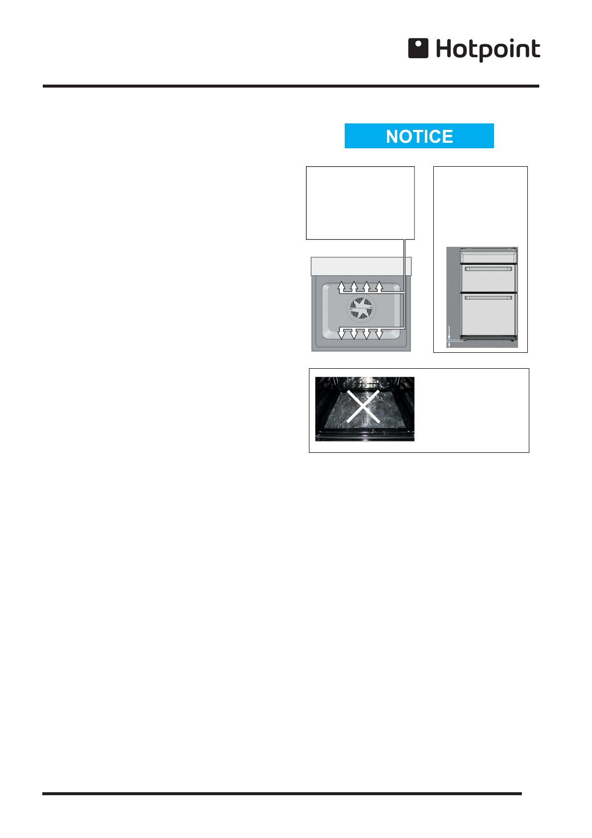
! ATTENTION
DURING INSTALLATION
THE FEET OF THE APPLIANCE
MUST BE LOWERED SO THAT
AN AIR GAP OF AT LEAST
10MM (1CM) IS LEFT BETWEEN
THE BASE OF THE APPLIANCE
AND THE FLOOR.
! VERY HOT SURFACES
YOU MUST KEEP THE OVEN
AND GRILL CAVITIES CLEAN
FOOD OR GREASE ON THESE
SURFACES COULD CAUSE
SMOKE AND POSSIBLY EVEN BURN
! ATTENTION
WHEN USING THE MAIN OVEN
YOU MUST ENSURE THAT THE
BASE OF THE CAVITY IS NOT
COVERED WITH ALUMINUM
FOIL, UTENSIL OR ANY OTHER
FORM OF COVERING. FAILURE
TO DO THIS MAY RESULT IN
THE CAVITY BEING DAMAGED.
10 mm
! ATTENTION! ATTENTION
! ATTENTION ! ATTENTION
! VERY HOT SURFACES! VERY HOT SURFACES


