Vent-a-Hood PRH6K36SS Installation guide

Type
Installation guide

This manual is also suitable for

Page 1L114A 0311A
U
L
CUS
R
Read and Save These Instructions
All Hoods Must Be Installed By A Qualied Installer
INSTALLATION INSTRUCTIONS
K-SERIES UNDER CABINET HOOD
Read All Instructions Thoroughly Before Beginning Installation
WARNING - TO REDUCE THE RISK OF FIRE, ELECTRIC SHOCK,
OR INJURY TO PERSONS, OBSERVE THE FOLLOWING:
A. Installation work and electrical wiring must be done by qualied person(s)
in accordance with all applicable codes and standards, including re-
rated construction. Switch power off at service panel and lock the service
disconnecting means to prevent power from being switched on accidentally
during installation.
B. When cutting or drilling into wall or ceiling, do not damage electrical wiring
and other hidden utilities.
C. Ducted fans must always be vented to the outdoors.
D. Sufcient air is needed for proper combustion and exhausting of gases
through the ue (chimney) of fuel burning equipment to prevent back
drafting. Follow the heating equipment manufacturers guideline and
safety standards such as those published by the National Fire Protection
Association (NFPA), and the American Society for Heating, Refrigeration
and Air Conditioning Engineers (ASHRAE), and local code authorities.
E. ASHRAE residential ventilation standard 62.2 limits exhaust fans (total) to
a maximum of 15 CFM per 100 square feet of occupiable space, unless a
back drafting test is performed or make-up air is provided. Consult a local
HVAC engineer for make-up air evaluation.
WARNING - TO REDUCE THE RISK OF FIRE, USE ONLY METAL
DUCTWORK
Page 2L114A 0311A
Ducting Do’s and Don’ts
NEVER restrict the duct size. The K250 blower unit requires 7” round duct or equivalent (32.5
square inches). Using Vent-A-Hood transitions (back page) will ensure proper efciency.
Do not use exible or corrugated duct. This type of duct will restrict airow and reduce
performance. Only use smooth, galvanized, metal duct. Observe local codes regarding special
duct requirements and placement of duct against combustibles. Make the duct run as short
and as straight as possible with as few turns as possible. Avoid sharp-angled turns. Instead,
use smooth, gradual turns such as adjustable elbows or 45 degree angled turns. For duct runs
over 20 feet, increase the duct diameter by one inch for every ten feet of duct. A 90 degree
elbow is equal to 5 feet of duct. Using Vent-A-Hood roof jacks or wall louvers (back page) will
ensure proper efciency. Airow must not be restricted at the end of the duct run. Do not use
screen wire or spring-loaded doors on wall louvers or roof jacks. Do not terminate venting into
an attic or chimney. Where possible, seal joints with duct tape. The hood must be ducted to the
outdoors without restrictions.
Blower Duct Size Sq. Inch Area
K250 3 1/4” x 10” rectangular or equivalent 32.5”
YES
NO
Smooth Duct
Smooth Gradual Turn
Flexible Duct
Sharp Angled Turns
Page 3L114A 0311A










Installation Details
1) Read all instructions thoroughly before beginning installation.
2) When installing the K-Series under cabinet hood, it is recommended that the bottom edge of the hood be located no more
than 21” - 24” from the cooking surface. Exceeding recommended mounting height may compromise performance.
3) Inspect the underside of the cabinet for a ush mounting surface. If the underside of the cabinet is recessed, install
wood strips to provide a ush surface for the hood mounting screws to engage.
4) Determine whether the hood will discharge horizontally or vertically. The hood is shipped to discharge vertically but is
easily converted to horizontal discharge by exchanging the discharge adapter on top of the hood (4 screws) with the
discharge cover on the back of the hood (2 screws). Use duct tape to seal the discharge adapter and discharge cover
to the hood.
5) IF THE HOOD IS TO BE “BACK VENTED”, PROCEED DIRECTLY TO STEP 6.
Install the duct from the outside of the home down to the location of the hood exhaust outlet allowing room for the
VP521 transition on the top of the hood (if applicable). If a VP521 transition is used, install the duct down to the location
of the transition outlet plus 1”. This will allow the transition to engage 1” inside of the duct. Consult the connection
diagram (below) for further details on exhaust outlet placement.
Use duct tape to seal all joints. A complete listing of available Vent-A-Hood ducting materials is provided on the back
page of this instruction sheet.
Transition height: 3 1/4” x 10” duct will connect directly to the exhaust outlet of the hood. Optional VP521 transition
to 7” round (sold separately) is 7 1/2” tall.
Page 4L114A 0311A
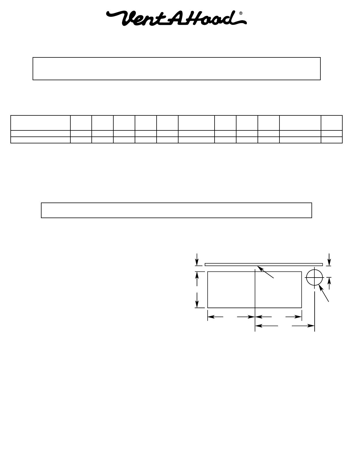
Wall Cutout for Horizontal Ducting
Viewed from Front
Bottom of
Cabinet
⁄"
3 ½"
5 ⁄" 5 ⁄"
6 ¼"
1 ⁄"
Electrical
C
L
Installation Details Continued
6) Remove the hood from its packaging and place on the oor or countertop in front of the cabinet where it will hang.
Warning: Do not operate hood without proper ground connection.
Warning: Make sure power is off and locked at the service disconnecting
means on the service panel during installation.
7) Determine whether the electrical wire will enter from the top or the back of the hood. Remove the electrical enclosure
cover (1 screw) and the top or back electrical enclosure knockout from the hood. Install an appropriate 1/2” UL listed
electrical wire clamp through the electrical knockout. Install electrical wiring from the electrical panel to the hood
location.
8) Insert the electrical wire through the electrical wire clamp allowing 3” - 4” of wire inside the enclosure for hookup.
Tighten the electrical wire clamp.
9) From inside the hood, using UL listed wire nuts, attach the “neutral” wire to the white lead, the “hot” wire to the black
lead, and the ground wire to the green lead inside the junction box. Replace the electrical cover previously removed
in Step 7.
10) FOR BACK VENTING APPLICATIONS ONLY. IF YOU ARE NOT BACK VENTING, PROCEED DIRECTLY TO STEP 12.
Note: Wall studs may interfere with back venting installations.
Additional framing may be required. It is necessary to cut a
duct access hole in the wall prior to installing the hood. Starting
2 1/8” above the bottom edge of the hood, cut a hole 3 1/2”
high x 10 1/4” wide (see diagram at right).
11) Install the duct from the outside of the home to the duct access
hole in the wall. Where possible, use duct tape to seal joints.
12) While aligning the duct and guiding the wires, position the
hood under the cabinet. The duct should connect together
as the hood is located in place. Note: Unless using the VP521
transition, the duct work must t inside the exhaust collar. If
using the VP521, 7” round duct should be placed with the non-
crimped end on the outside of the collar of the VP521 exhaust
outlet. Using the four screws provided, attach the hood to the
bottom of the cabinet.
14) Refer to the Owner Maintenance Guide Operating Instructions for proper hood operation. Test all blower and light
functions to ensure they are operating properly.
Model Volts Amps Hz RPM
CFM
Equivalent CFM
CFM
CFM
CFM
Minimum Round
Duct Size
Sones
#
K250 (Top Vent) 115 3.2 60 1550 250 375 223 220 190 7" (38 in.
2
) 7.4
K250 (Back Vent) 115 3.2 60 1550 220 330 196 194 167 7" (38 in.
2
) 7.4
Because the Magic Lung
®
blower uses centrifugal ltration rather than conventional bafe or mesh lters, the Magic Lung
®
blower can handle cooking equipment with higher cubic feet per minute (CFM) requirements and can deliver equivalent CFM much more
efciently than other than other ltration systems. When comparing the Magic Lung
®
with other blower units made by other manufacturers, use the “Equivalent CFM”.
#
Ratings in accordance with the Standard Test Code by the Energy Systems Laboratory of the Texas Engineering Experiment Station.
Page 5L114A 0311A
VENTING ACCESSORIES
WALL LOUVER
6”
7”
8”
8 ⁄”
Back
View
1 ½” Flange
WALL LOUVER
11”
11”
Back
View
1 ½” Flange
WALL LOUVER
13”
13”
Back
View
1 ½” Flange
RECTANGULAR WALL LOUVER
3 ¼”
10”
8 ½”
6”
1 ½” FLANGE
2” FLANGE
LOW PROFILE ROOF JACK
(MAXIMUM 4/12 PITCH)
6 ½”
16 ¾”
16 ¾”
LOW PROFILE ROOF JACK
(MAXIMUM 4/12 PITCH)
10 ½”
22 ½”
20 ¾”
ADJUSTABLE ELBOW
6”
7”
8”
VP513 - 8 ½”
VP514 - 9 ⁄”
VP515 - 10 ⁄”
ROUND DUCT PIPE
36”
6”
7”
8”
3 ¼” RECTANGULAR DUCT PIPE
30”
10”
12”
16”
3 ¼”
6” RECTANGULAR DUCT PIPE
24”
8 ½”
6”
OFFSET L & R TRANSITION
FOR ISLAND BLOWERS
8”
12”
5”
16”
SIDE VENT TRANSITION L & R
FOR ISLAND BLOWERS
19”
8”
16”
5”
“YTRANSITION
18”
10”
12”
OFFSET KIT - ROUND
16”
11”
6”
7”
10 ½”
OFFSET KIT - RECTANGULAR
16”
11”
6”
11”
3 ¼”
10”
STANDARD ISLAND TRANSITION
8”
9”
16”
5”
CLUSTER BLOWER TRANSITION
18 ½”
12”
11 ¼”
BACK/SIDE VENT ELBOW
12”
6”
16”
8” Round
8 ½”
3 ¼” x 10” BACK VENT ELBOW
4 ¼”
10”
14”
3 ¼”
3 ¼”
MULTI-BLOWER TRANSITION
VP562 - 17 ½”
VP563 - 16 ½”
10”
12”
VP562 - 23 ¼”
VP563 - 30 ½”
3 ¼” x 10” TO 7” TRANSITION
7”
7 ½”
3 ¼”
10”
M1200 STANDARD TRANSITION
10”
9”
8”
21”
LOW PROFILE ROOF JACK
(MINIMUM 4/12 PITCH)
6 ½”
16 ¾”
16 ¾”
LOW PROFILE ROOF JACK
(MINIMUM 4/12 PITCH)
10 ½”
22 ½”
20 ¾”
MODEL DESCRIPTION PRICE
VP526 6” Round
VP527 7” Round
VP528 8” Round
MODEL DESCRIPTION PRICE
VP554 10” Round
MODEL DESCRIPTION PRICE
VP555 12” Round
MODEL DESCRIPTION PRICE
VP538 6” x 8-1/2”
VP560 3-1/4” x 10”
MODEL DESCRIPTION PRICE
VP539 6” Round
VP540 7” Round
VP541 8” Round
MODEL DESCRIPTION PRICE
VP552 10” Round
VP553 12” Round
MODEL DESCRIPTION PRICE
VP539-HP 6” Round
VP540-HP 7” Round
VP541-HP 8” Round
MODEL DESCRIPTION PRICE
VP552-HP 10” Round
VP553-HP 12” Round
MODEL DESCRIPTION PRICE
VP513 6” Round
VP514 7” Round
VP515 8” Round
MODEL DESCRIPTION PRICE
VP561 8” to 6” x 8-1/2”
MODEL DESCRIPTION PRICE
VP559 3-1/4” x 10”
MODEL DESCRIPTION PRICE
VP521 3-1/4” x 10 to 7”
MODEL DESCRIPTION PRICE
VP562 6” & 8” to 10”
VP563 8” & 8” to 12”
MODEL DESCRIPTION PRICE
VP566 M1200 Transition
MODEL DESCRIPTION PRICE
VP565 5” x 16” to 8” Rnd
MODEL DESCRIPTION PRICE
VP564 8” & 8” to 12”
MODEL DESCRIPTION PRICE
VP542 Top Left
VP543 Top Right
MODEL DESCRIPTION PRICE
VP544 Side Left
VP545 Side Right
MODEL DESCRIPTION PRICE
VP529 6” Rnd to 7” Rnd
MODEL DESCRIPTION PRICE
VP550 6” to 3-1/4” x 10”
MODEL DESCRIPTION PRICE
VP517 8” & 8” to 12”
VP518 6” & 8” to 12”
VP551 6” & 8” to 10”
MODEL DESCRIPTION PRICE
VP500 6” Round
VP501 7” Round
VP502 8” Round
MODEL DESCRIPTION PRICE
VP504 3-1/4” x 10”
VP505 3-1/4” x 12”
VP506 3-1/4” x 16”
MODEL DESCRIPTION PRICE
VP507 6” x 8-1/2”
  • Page 1 1
  • Page 2 2
  • Page 3 3
  • Page 4 4
  • Page 5 5

Vent-a-Hood PRH6K36SS Installation guide

Type
Installation guide
This manual is also suitable for

Ask a question and I''ll find the answer in the document

Finding information in a document is now easier with AI